EP0806784A2 - Appareil de commutation avec des lignes de connexion mobiles - Google Patents
Appareil de commutation avec des lignes de connexion mobiles Download PDFInfo
- Publication number
- EP0806784A2 EP0806784A2 EP97890079A EP97890079A EP0806784A2 EP 0806784 A2 EP0806784 A2 EP 0806784A2 EP 97890079 A EP97890079 A EP 97890079A EP 97890079 A EP97890079 A EP 97890079A EP 0806784 A2 EP0806784 A2 EP 0806784A2
- Authority
- EP
- European Patent Office
- Prior art keywords
- switching device
- lines
- carrier
- section
- adjacent
- Prior art date
- Legal status (The legal status is an assumption and is not a legal conclusion. Google has not performed a legal analysis and makes no representation as to the accuracy of the status listed.)
- Granted
Links
Images


Classifications
-
- H—ELECTRICITY
- H01—ELECTRIC ELEMENTS
- H01H—ELECTRIC SWITCHES; RELAYS; SELECTORS; EMERGENCY PROTECTIVE DEVICES
- H01H71/00—Details of the protective switches or relays covered by groups H01H73/00 - H01H83/00
- H01H71/08—Terminals; Connections
- H01H71/082—Connections between juxtaposed circuit breakers
Definitions
- the invention relates to a switching device for installation in a control cabinet, which switching device has lines for establishing electrical connections to the connection terminals of a further switching device arranged immediately adjacent.
- a control cabinet generally has a plurality of rails spaced apart from one another, on which rails the various switching devices are fixed and then electrically connected to one another.
- a fault current module has become known from EP-A1-649 158 , which has a rigid bracket which runs horizontally with respect to the installation position in a control cabinet and in which bracket the lines necessary for establishing electrical connections to an adjacent circuit breaker lead are. The ends of the lines protrude from the bracket in such a way that when the circuit breaker and FI module are arranged next to each other on a mounting rail, they engage in the connection terminals of the circuit breaker.
- this is achieved in that the lines are fixed on the switching device relative to the switching device along a predetermined path.
- the lines can thus be removed from the connecting terminals of the adjacent switching device, thereby releasing the mechanical connection of the two switching devices themselves without any movement of the switching device provided with the lines.
- a preferred embodiment of the invention can consist in that the lines are fixed on the switching device so as to be translationally displaceable.
- the lines are arranged on a common carrier, which carrier is mounted in the switching device so as to be displaceable parallel to the side surfaces of the switching device between a retracted and an extended position.
- any neighboring switching device designed in accordance with the standards can be wired in such a configuration.
- the carrier has a first straight section which runs parallel to the side surfaces of the switching device, which section runs inside the switching device and has one end extending through a switching device transverse wall.
- the carrier has a second section, which is fixed at the end of the first section which extends through the switching device transverse wall and runs essentially normal to this, completely outside the switching device and which has the connection terminals of the adjacent switching device connectable cable ends.
- a further feature of the invention can be that the carrier section running parallel to the side surfaces of the switching device has a spring-attached projection at its end projecting through the switching device transverse wall, which in the extended position of the carrier is located on an edge of the switching device transverse wall starts. This allows the carrier to be detachably fixed in its extended position, as a result of which the neighboring switching device can be brought into its position in a particularly simple manner.
- the carrier is formed by a flat plate, on the surfaces of which the lines are fixed, since this embodiment can be produced particularly easily.
- the plate has walls running essentially normal to these surfaces on each surface equipped with lines.
- the second carrier section running outside the switching device has rail-shaped approaches, preferably extending essentially over the entire length of the second carrier section, on which a cover covering the lines can be positively fixed. This means that the cables can be enclosed on all sides and electrically isolated from their environment.
- extensions extending in the direction of the carrier plate are arranged on the inside of the cover.
- the lines between the carrier plate and cover can be clamped and fixed on the carrier, which means that further fastening measures, such as Gluing, screwing or the like can be omitted.
- the cover has a nose in the region of its side edge adjacent to the switching device, which nose engages in a corresponding recess in the switching device transverse wall in the retracted position of the carrier.
- the cover is thus secured in the retracted position of the carrier against horizontal displacements, so that it can no longer be detached from the carrier plate. Measures to permanently close the lid, e.g. Gluing is not required.
- peg-shaped projections are formed, which engage in correspondingly mirror-inverted holes in the side wall of the adjacent further switching device in the engaged state, because the adjacent switching device is in exact alignment the side wall can be created.
- Another object of the invention is to provide a circuit breaker which comprises a switching device of the type described hitherto, has both RCD and CB function, is of compact design and is easy to wire.
- the switching device is formed by a fault current module comprising a switch lock, a summation current transformer and a circuit of the summation current transformer that actuates the switch lock
- the adjacent switching device is formed by a circuit breaker
- the switch lock of the fault current module with one through the side walls from Fault current module and tripping finger is provided through which the switch lock of the adjacent circuit breaker can be actuated.
- the switch contacts of the circuit breaker are also used for switching off if the FI module responds. Separate, series-connected contacts of the FI part therefore do not need to be provided, which results in a downsizing of the overall arrangement.
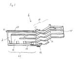
- a switching device 1 for control cabinets which is to be electrically connected to a further switching device 4 arranged directly adjacent, with corresponding lines 2 in order to avoid their manual laying.
- the lines are provided according to the invention 2 relative to the switching device 1 along a predetermined path movable to fix this.
- This movability can be realized, for example, in that the lines 2 are arranged so as to be pivotable about axes 5. However, the lines 2 are preferably slidably displaceable, in particular slidably mounted parallel to the side walls 10, 11 of the switching device 1.
- the lines 2 could each be fixed on the switching device 1 so as to be movable, that is to say pivotable or displaceable, but for reasons of simpler handling, it is expedient to fix them together on the switching device 1 so as to be movable.
- the lines 2 are preferably mechanically connected to one another, whereby the joint mobility is automatically given.
- the axes 5 would then be combined to form a common axis or at least all axes 5 would be arranged in alignment with one another.
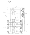
- the switching device 1 is designed as a fault current module, which itself has no switch contacts but only the fault current detection circuit with the associated switch lock.
- the fault current detection circuit is formed from a switch lock, a summation current transformer 17 and a circuit of the summation current transformer 17 that actuates the switch lock. To maintain clarity, only the summation current transformer 17 is shown in FIG.
- the neighboring switching device 4 is a circuit breaker.
- the switch lock of the residual current module has a trigger finger 15, which trigger finger 15 protrudes through the side wall 11 of the residual current module and through the side wall 40 of the circuit breaker and can actuate the switch lock of the circuit breaker (see FIG. 8).
- the switch contacts of the circuit breaker are thus used both for switching off in the event of a line overload and in the event of a fault current.
- the invention is in no way limited to this embodiment variant, but rather can be transferred to any type of device which can be installed in control cabinets. Examples of this are: circuit breakers with an adjacent FI switch; Miniature circuit breakers with adjacent impulse switches, staircase automatons, etc.
- a carrier 6 is provided, on which the lines 2 are arranged.
- the carrier 6 is mounted parallel to the side surfaces 10, 11 of the switching device 1 between a retracted and an extended position in the switching device 1.
- this carrier 6 The most important component of this carrier 6 is its section 60, which runs parallel to the side surfaces 10, 11.
- This section 60 like a drawer, is displaceably guided within the switching device 1 and extends with one end 61 through one of the switching device transverse walls 12, 13.
- the lower transverse wall 12 was selected for this purpose, but it would be entirely equivalent to carry out the support section 60 through the upper transverse wall 13.
- a second section 62 which is essentially normal to this section 60 fixed. This is entirely outside the switching device 1 and carries the line ends 20. These are distributed on the carrier section 62 so that when the carrier 6 moves in the direction of the arrow 8 into the terminals 3 of one immediately adjacent, that is to say to the side wall 11 extend further arranged switching device 4.
- the first carrier section 60 also has a spring-mounted extension 63 at its end 61 which projects through the transverse wall 12.
- This extension 63 is located in the retracted position of the carrier 6 inside the switching device 1, in the extended carrier position it protrudes just beyond the transverse wall 12 and can thus attach to the edge 64 of the transverse wall 12 (cf. also FIG. 4 ).
- the carrier 6 can thereby be locked in its extended position.
- the carrier 6 is formed by a flat plate 65, on the surfaces of which the lines 2 are fixed. (To maintain clarity, only one of the lines 2 is shown in FIG. 3). According to the embodiment shown in the drawings, all lines 2 are fixed on one and the same surface of plate 65, namely on the surface of plate 65 facing away from further switching device 4. However, within the meaning of the invention it is also entirely possible to distribute the lines 2 on both surfaces of the plate 65 in order to e.g. with the same plate dimensions to accommodate lines 2 of larger cross section, or to arrange the lines 2 on the surface of the plate 65 facing away from the further switching device 4.
- the lines 2 are sufficiently insulated from one another. This could be realized, for example, in that the lines 2 are coated with an insulating material, e.g. Pour plastic.
- Another possibility is to equip the plate 65 on each surface equipped with lines 2 with walls 66 running essentially normal to these surfaces. This creates individual chambers in which the lines 2 are received, insulated from one another.
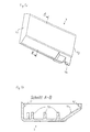
- a cover 7 which covers the lines 2 in the region of the second carrier section 62.
- Rail-shaped lugs 67 are arranged on the carrier section 62 and likewise rail-shaped lugs 75 are arranged in the cover 7 itself (cf. FIGS. 5 a, b) in order to secure it in a form-fitting manner.
- the cover 7 is open on its end face 72 facing the switching device 1, but is closed on the end face facing away from the switching device 1 by an end wall 71. The cover 7 can thus be pushed onto the carrier section 62 in the direction of the arrow 9 in FIG.
- extensions 73 extending in the direction of the carrier plate 65 are arranged. As can be seen in FIG. 6, these extensions 73 are of such a height that they are supported on the lines 2 and thus clamp them between the carrier plate 65 and the cover 7.
- the cover 7 In the area of its side edge 72 adjacent to the switching device 1, the cover 7 has a nose 74, which nose 74 engages in a corresponding recess in the switching device transverse wall 12 in the retracted position of the carrier 6 (see FIG. 7).
- the movement of the switch lock of the switching device 1 is transmitted to the switch lock of the adjacent circuit breaker by a trigger finger 15 protruding through the side wall 11. So that this trigger finger 15 can be inserted exactly into the corresponding socket of the circuit breaker switch lock when the two switching devices 1, 4 are joined together, it is favorable to design the side wall 11 to which the further switching device 4 can be attached with peg-shaped lugs 16 to provide.
- the lugs 16 engage in mirror-inverted holes in the side wall of the adjacent switching device 4 and thus ensure an exact alignment of the two switching devices 1, 4.
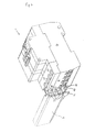
- FIGS. 8-10 The fault current module 1 is fixed (snapped on) on the control cabinet rail and the carrier 6 is brought into its extended position.
- the circuit breaker 4 is also arranged on the rail at a small horizontal distance from the fault current module (Fig. 8).
- the two switching devices 1, 4 are now pushed towards one another until the lugs 16 engage in the corresponding bores and the trigger finger 15 in the corresponding socket and the switching devices 1, 4 lie with their side surfaces 11, 40 against one another (FIG. 9). .
Landscapes
- Switch Cases, Indication, And Locking (AREA)
- Patch Boards (AREA)
- Coupling Device And Connection With Printed Circuit (AREA)
- Push-Button Switches (AREA)
- Keying Circuit Devices (AREA)
- Input Circuits Of Receivers And Coupling Of Receivers And Audio Equipment (AREA)
- Structure Of Telephone Exchanges (AREA)
- Breakers (AREA)
- Casings For Electric Apparatus (AREA)
- Trip Switchboards (AREA)
- Cable Accessories (AREA)
- Mechanical Light Control Or Optical Switches (AREA)
- Use Of Switch Circuits For Exchanges And Methods Of Control Of Multiplex Exchanges (AREA)
Priority Applications (1)
| Application Number | Priority Date | Filing Date | Title |
|---|---|---|---|
| AT97890079T ATE254335T1 (de) | 1996-05-07 | 1997-04-29 | Schaltgerät mit bewegbaren verbindungs-leitungen |
Applications Claiming Priority (3)
| Application Number | Priority Date | Filing Date | Title |
|---|---|---|---|
| AT81396 | 1996-05-07 | ||
| AT813/96 | 1996-05-07 | ||
| AT0081396A AT411115B (de) | 1996-05-07 | 1996-05-07 | Schaltgerät mit bewegbaren verbindungs-leitungen |
Publications (3)
| Publication Number | Publication Date |
|---|---|
| EP0806784A2 true EP0806784A2 (fr) | 1997-11-12 |
| EP0806784A3 EP0806784A3 (fr) | 1998-05-20 |
| EP0806784B1 EP0806784B1 (fr) | 2003-11-12 |
Family
ID=3500323
Family Applications (1)
| Application Number | Title | Priority Date | Filing Date |
|---|---|---|---|
| EP97890079A Expired - Lifetime EP0806784B1 (fr) | 1996-05-07 | 1997-04-29 | Appareil de commutation avec des lignes de connexion mobiles |
Country Status (10)
| Country | Link |
|---|---|
| EP (1) | EP0806784B1 (fr) |
| AT (2) | AT411115B (fr) |
| AU (1) | AU715916B2 (fr) |
| CZ (1) | CZ293608B6 (fr) |
| DE (1) | DE59710978D1 (fr) |
| ES (1) | ES2109913T3 (fr) |
| GR (1) | GR970300052T1 (fr) |
| HU (1) | HU221670B1 (fr) |
| PL (1) | PL182547B1 (fr) |
| SK (1) | SK283786B6 (fr) |
Cited By (11)
| Publication number | Priority date | Publication date | Assignee | Title |
|---|---|---|---|---|
| FR2772979A1 (fr) * | 1997-12-18 | 1999-06-25 | Schneider Electric Sa | Dispositif de raccordement electrique d'un bloc differentiel sur un disjoncteur ou analogue et bloc differentiel equipe d'un tel dispositif |
| FR2779269A1 (fr) * | 1998-05-29 | 1999-12-03 | Hager Electro | Dispositif de couplage de deux elements electriques modulaires accoles |
| EP1100105A1 (fr) * | 1999-11-12 | 2001-05-16 | Schneider Electric Industries SA | Dispositif de précâblage pour contacteurs |
| EP1278224A1 (fr) * | 2001-07-18 | 2003-01-22 | Schneider Electric Industries SAS | Dispositif de raccordement électrique de deux appareils électriques montés côte à côte sur un mème support de montage |
| DE102005050318B3 (de) * | 2005-10-20 | 2007-03-15 | Siemens Ag | Wandlereinheit und Vorrichtung zur allstromsensitiven Erfassung eines elektrischen Differenzstromes |
| EP1770739A1 (fr) * | 2005-09-29 | 2007-04-04 | Hager-Electro SAS | Bloc différentiel à tiroir coulissant selon une trajectoire inclinée |
| EP2031627A3 (fr) * | 2007-08-27 | 2010-09-15 | Phoenix Contact GmbH & Co. KG | Unité de construction comprenant un disjoncteur à courant de défaut et un appareil de protection contre les surtensions |
| RU2464667C2 (ru) * | 2007-07-26 | 2012-10-20 | Бтичино С.П.А. | Устройство защиты от остаточных токов для электрического выключателя |
| EP2680379A1 (fr) | 2012-06-28 | 2014-01-01 | Schneider Electric Industries SAS | Dispositif de verrouillage d'au moins un appareil électrique modulaire sur un rail de montage, et appareil de coupure électrique fixé sur le rail au moyen d'un tel dispositif |
| CN103510768A (zh) * | 2013-09-29 | 2014-01-15 | 安徽鑫龙电器股份有限公司 | 一种用于高压开关柜的断路器门锁机构及其安装方法 |
| WO2021164895A1 (fr) * | 2020-02-19 | 2021-08-26 | Dehn Se + Co Kg | Dispositif de protection contre les surtensions, ensembles de protection contre les surtensions comportant un tel dispositif de protection contre les surtensions et procédé d'assemblage d'un ensemble de protection contre les surtensions |
Families Citing this family (2)
| Publication number | Priority date | Publication date | Assignee | Title |
|---|---|---|---|---|
| ES2155024B1 (es) * | 1999-05-14 | 2001-11-01 | Power Controls Iberica Sl | Carcasa para aparatos electricos. |
| US9842715B2 (en) * | 2015-12-04 | 2017-12-12 | Eaton Corporation | Electrical switching apparatus and strain relief assembly therefor |
Family Cites Families (6)
| Publication number | Priority date | Publication date | Assignee | Title |
|---|---|---|---|---|
| DE1145248B (de) * | 1959-12-01 | 1963-03-14 | Stotz Kontakt Gmbh | Klemmenanordnung, insbesondere fuer Installationsselbstschalter |
| DE2654373A1 (de) * | 1976-12-01 | 1978-06-08 | Licentia Gmbh | Mit einem mehrpoligen leitungsschutzschalter kombinierter fehlerstromschutzschalter |
| DE7813854U1 (de) * | 1978-05-08 | 1979-10-11 | Licentia Patent-Verwaltungs-Gmbh, 6000 Frankfurt | Mit einem mehrpoligen Leitungsschutzschalter kombinierter Fehlerstromschutzschalter |
| DE8804649U1 (de) * | 1988-04-08 | 1988-06-16 | Murrelektronik GmbH, 7155 Oppenweiler | Elektrisches Gerät, z.B. Schaltgerät, Einschaltverzögerer od. dgl. |
| FR2640422B1 (fr) * | 1988-12-14 | 1996-04-05 | Merlin Gerin | Dispositif d'assemblage modulaire d'un disjoncteur differentiel multipolaire |
| FR2711449B1 (fr) * | 1993-10-18 | 1995-12-22 | Merlin Gerin | Bloc de protection différentielle avec passage des câbles. |
-
1996
- 1996-05-07 AT AT0081396A patent/AT411115B/de not_active IP Right Cessation
-
1997
- 1997-04-28 HU HU9700820A patent/HU221670B1/hu not_active IP Right Cessation
- 1997-04-29 AT AT97890079T patent/ATE254335T1/de active
- 1997-04-29 DE DE59710978T patent/DE59710978D1/de not_active Expired - Lifetime
- 1997-04-29 EP EP97890079A patent/EP0806784B1/fr not_active Expired - Lifetime
- 1997-04-29 ES ES97890079T patent/ES2109913T3/es not_active Expired - Lifetime
- 1997-05-06 CZ CZ19971373A patent/CZ293608B6/cs not_active IP Right Cessation
- 1997-05-07 SK SK580-97A patent/SK283786B6/sk not_active IP Right Cessation
- 1997-05-07 AU AU20095/97A patent/AU715916B2/en not_active Ceased
- 1997-05-07 PL PL97319846A patent/PL182547B1/pl not_active IP Right Cessation
- 1997-12-31 GR GR970300052T patent/GR970300052T1/el unknown
Cited By (20)
| Publication number | Priority date | Publication date | Assignee | Title |
|---|---|---|---|---|
| FR2772979A1 (fr) * | 1997-12-18 | 1999-06-25 | Schneider Electric Sa | Dispositif de raccordement electrique d'un bloc differentiel sur un disjoncteur ou analogue et bloc differentiel equipe d'un tel dispositif |
| EP0926695A1 (fr) * | 1997-12-18 | 1999-06-30 | Schneider Electric Sa | Dispositif de raccordement électrique d'un bloc différentiel sur un disjoncteur ou analogue et bloc différentiel équipé d'un tel dispositif |
| TR199802642A3 (tr) * | 1997-12-18 | 1999-10-21 | Schneider Electric S.A. | Bir diferansiyel ünitesinin bir devre kesiciye veya benzeri bir cihaza elektriksel baglantisi için bir düzenek ve böyle bir düzenek ile donatilmis bir diferansiyel ünitesi. |
| FR2779269A1 (fr) * | 1998-05-29 | 1999-12-03 | Hager Electro | Dispositif de couplage de deux elements electriques modulaires accoles |
| WO1999063563A1 (fr) * | 1998-05-29 | 1999-12-09 | Hager Electro | Dispositif de couplage de deux elements electriques modulaires accoles |
| AU741444B2 (en) * | 1998-05-29 | 2001-11-29 | Hager Electro | Device for coupling two attached modular electrical elements |
| EP1100105A1 (fr) * | 1999-11-12 | 2001-05-16 | Schneider Electric Industries SA | Dispositif de précâblage pour contacteurs |
| FR2801165A1 (fr) * | 1999-11-12 | 2001-05-18 | Schneider Electric Ind Sa | Dispositif de precablage pour contacteurs |
| US6388894B1 (en) | 1999-11-12 | 2002-05-14 | Schneider Electric Industries Sa | Pre-wiring device for contactors |
| FR2827702A1 (fr) * | 2001-07-18 | 2003-01-24 | Schneider Electric Ind Sa | Dispositif de raccordement electrique de deux appareils electriques montes cote a cote sur un meme support de montage |
| EP1278224A1 (fr) * | 2001-07-18 | 2003-01-22 | Schneider Electric Industries SAS | Dispositif de raccordement électrique de deux appareils électriques montés côte à côte sur un mème support de montage |
| EP1770739A1 (fr) * | 2005-09-29 | 2007-04-04 | Hager-Electro SAS | Bloc différentiel à tiroir coulissant selon une trajectoire inclinée |
| DE102005050318B3 (de) * | 2005-10-20 | 2007-03-15 | Siemens Ag | Wandlereinheit und Vorrichtung zur allstromsensitiven Erfassung eines elektrischen Differenzstromes |
| RU2464667C2 (ru) * | 2007-07-26 | 2012-10-20 | Бтичино С.П.А. | Устройство защиты от остаточных токов для электрического выключателя |
| EP2031627A3 (fr) * | 2007-08-27 | 2010-09-15 | Phoenix Contact GmbH & Co. KG | Unité de construction comprenant un disjoncteur à courant de défaut et un appareil de protection contre les surtensions |
| EP2680379A1 (fr) | 2012-06-28 | 2014-01-01 | Schneider Electric Industries SAS | Dispositif de verrouillage d'au moins un appareil électrique modulaire sur un rail de montage, et appareil de coupure électrique fixé sur le rail au moyen d'un tel dispositif |
| FR2992783A1 (fr) * | 2012-06-28 | 2014-01-03 | Schneider Electric Ind Sas | Dispositif de verrouillage d'au moins un appareil electrique modulaire sur un rail de montage, et appareil de coupure electrique fixe sur le rail au moyen d'un tel dispositif |
| CN103515845A (zh) * | 2012-06-28 | 2014-01-15 | 施耐德电器工业公司 | 用于将电气设备锁定在导轨上的装置以及电气开关设备 |
| CN103510768A (zh) * | 2013-09-29 | 2014-01-15 | 安徽鑫龙电器股份有限公司 | 一种用于高压开关柜的断路器门锁机构及其安装方法 |
| WO2021164895A1 (fr) * | 2020-02-19 | 2021-08-26 | Dehn Se + Co Kg | Dispositif de protection contre les surtensions, ensembles de protection contre les surtensions comportant un tel dispositif de protection contre les surtensions et procédé d'assemblage d'un ensemble de protection contre les surtensions |
Also Published As
| Publication number | Publication date |
|---|---|
| ATA81396A (de) | 2003-02-15 |
| PL319846A1 (en) | 1997-11-10 |
| AU2009597A (en) | 1997-11-13 |
| HU221670B1 (hu) | 2002-12-28 |
| HUP9700820A2 (hu) | 1998-01-28 |
| ES2109913T3 (es) | 2004-07-01 |
| CZ137397A3 (cs) | 1998-12-16 |
| CZ293608B6 (cs) | 2004-06-16 |
| AT411115B (de) | 2003-09-25 |
| ES2109913T1 (es) | 1998-02-01 |
| EP0806784A3 (fr) | 1998-05-20 |
| ATE254335T1 (de) | 2003-11-15 |
| SK283786B6 (sk) | 2004-01-08 |
| GR970300052T1 (en) | 1997-12-31 |
| DE59710978D1 (de) | 2003-12-18 |
| AU715916B2 (en) | 2000-02-10 |
| PL182547B1 (pl) | 2002-01-31 |
| HU9700820D0 (en) | 1997-06-30 |
| HUP9700820A3 (en) | 1999-11-29 |
| EP0806784B1 (fr) | 2003-11-12 |
| SK58097A3 (en) | 1998-07-08 |
Similar Documents
| Publication | Publication Date | Title |
|---|---|---|
| EP0709920B1 (fr) | Système de commande modulaire | |
| EP0899818B1 (fr) | Borne de connexion électrique, notamment pour utilisation sur des plaques de circuits imprimés | |
| AT411115B (de) | Schaltgerät mit bewegbaren verbindungs-leitungen | |
| EP1914838A1 (fr) | Interrupteur d'installation modulaire | |
| DD292105A5 (de) | Schaltvorrichtung mit geschuetzten unterbrechern | |
| EP1856709B1 (fr) | Commutateur electromecanique | |
| DE4124487C2 (de) | Adapter | |
| EP0133152A1 (fr) | Dispositif pour la connexion de conducteurs auxiliaires à un appareil de commutation ou une combinaison d'appareils de commutation | |
| DE2515152B2 (de) | Elektrische Schaltanlage für Niederspannung | |
| DE69420923T2 (de) | Differentialschutzblock mit Kabeldurchgang | |
| EP1851839B1 (fr) | Installation de commutation | |
| DE4312617C2 (de) | Elektrisches Schaltfeld, insbesondere für Mittelspannungsanlagen | |
| EP0821454B1 (fr) | Dispositif de raccordement pour installation électrique | |
| EP1784847B1 (fr) | Appareil d'installation electrique | |
| DE102004037083A1 (de) | Überspannungsableiter-Anordnung mit einer als Bestandteil eines Gehäuses ausführbaren Trägerplatte | |
| EP2786389B1 (fr) | Système d'aimant permanent pour un circuit d'attaque à arc lumineux et appareil de commutation | |
| EP0223732B1 (fr) | Disjoncteur multipolaire de puissance basse tension avec barres de courant | |
| DE10003349A1 (de) | Halterungseinrichtung zur Befestigung wenigstens eines elektrischen Schaltgerätes auf einer Hutprofiltragschiene | |
| DE4337254B4 (de) | Fehlerstrommodul, der mit Leitungsschutzschaltern zusammensetzbar ist | |
| DE10146503A1 (de) | Elektrische Installationsverteilung | |
| DE69607136T2 (de) | Schalttafel und Anschlusseinrichtung für elektrische Installationen mit modularen Einrichtungen | |
| DE102005049873A1 (de) | Überspannungsableiter-Anordnung mit einer als Bestandteil eines Gehäuses ausführbaren Trägerplatte | |
| DE10106270A1 (de) | Geräteeinheit mit einer Kontaktvorrichtung zur lösbaren Verbindung mit ortsfesten Stromschienen | |
| DE102012215528B4 (de) | Schalter, insbesondere Leistungsschalter für Niederspannungen | |
| DE69808836T2 (de) | Adapter zur modularen Verbindung elektrischer Geräte zu einem elektrischen Verteilungssystem auf Basis von Schiene |
Legal Events
| Date | Code | Title | Description |
|---|---|---|---|
| PUAI | Public reference made under article 153(3) epc to a published international application that has entered the european phase |
Free format text: ORIGINAL CODE: 0009012 |
|
| AK | Designated contracting states |
Kind code of ref document: A2 Designated state(s): AT BE CH DE DK ES FI FR GB GR IE IT LI LU MC NL PT SE |
|
| AX | Request for extension of the european patent |
Free format text: AL PAYMENT 970530;LT PAYMENT 970530;LV PAYMENT 970530;RO PAYMENT 970530;SI PAYMENT 970530 |
|
| ITCL | It: translation for ep claims filed |
Representative=s name: SAMA DANIELE |
|
| EL | Fr: translation of claims filed | ||
| IECL | Ie: translation for ep claims filed | ||
| REG | Reference to a national code |
Ref country code: ES Ref legal event code: BA2A Ref document number: 2109913 Country of ref document: ES Kind code of ref document: T1 |
|
| TCNL | Nl: translation of patent claims filed | ||
| PUAL | Search report despatched |
Free format text: ORIGINAL CODE: 0009013 |
|
| GBC | Gb: translation of claims filed (gb section 78(7)/1977) | ||
| AK | Designated contracting states |
Kind code of ref document: A3 Designated state(s): AT BE CH DE DK ES FI FR GB GR IE IT LI LU MC NL PT SE |
|
| AX | Request for extension of the european patent |
Free format text: AL PAYMENT 970530;LT PAYMENT 970530;LV PAYMENT 970530;RO PAYMENT 970530;SI PAYMENT 970530 |
|
| 17P | Request for examination filed |
Effective date: 19981120 |
|
| 17Q | First examination report despatched |
Effective date: 20020606 |
|
| GRAH | Despatch of communication of intention to grant a patent |
Free format text: ORIGINAL CODE: EPIDOS IGRA |
|
| GRAS | Grant fee paid |
Free format text: ORIGINAL CODE: EPIDOSNIGR3 |
|
| GRAA | (expected) grant |
Free format text: ORIGINAL CODE: 0009210 |
|
| AK | Designated contracting states |
Kind code of ref document: B1 Designated state(s): AT BE CH DE DK ES FI FR GB GR IE IT LI LU MC NL PT SE |
|
| AX | Request for extension of the european patent |
Extension state: AL LT LV RO SI |
|
| PG25 | Lapsed in a contracting state [announced via postgrant information from national office to epo] |
Ref country code: NL Free format text: LAPSE BECAUSE OF FAILURE TO SUBMIT A TRANSLATION OF THE DESCRIPTION OR TO PAY THE FEE WITHIN THE PRESCRIBED TIME-LIMIT Effective date: 20031112 Ref country code: IE Free format text: LAPSE BECAUSE OF FAILURE TO SUBMIT A TRANSLATION OF THE DESCRIPTION OR TO PAY THE FEE WITHIN THE PRESCRIBED TIME-LIMIT Effective date: 20031112 Ref country code: GB Free format text: LAPSE BECAUSE OF FAILURE TO SUBMIT A TRANSLATION OF THE DESCRIPTION OR TO PAY THE FEE WITHIN THE PRESCRIBED TIME-LIMIT Effective date: 20031112 Ref country code: FI Free format text: LAPSE BECAUSE OF FAILURE TO SUBMIT A TRANSLATION OF THE DESCRIPTION OR TO PAY THE FEE WITHIN THE PRESCRIBED TIME-LIMIT Effective date: 20031112 |
|
| REG | Reference to a national code |
Ref country code: GB Ref legal event code: FG4D Free format text: NOT ENGLISH |
|
| REG | Reference to a national code |
Ref country code: CH Ref legal event code: EP |
|
| REF | Corresponds to: |
Ref document number: 59710978 Country of ref document: DE Date of ref document: 20031218 Kind code of ref document: P |
|
| REG | Reference to a national code |
Ref country code: IE Ref legal event code: FG4D Free format text: GERMAN |
|
| PG25 | Lapsed in a contracting state [announced via postgrant information from national office to epo] |
Ref country code: SE Free format text: LAPSE BECAUSE OF FAILURE TO SUBMIT A TRANSLATION OF THE DESCRIPTION OR TO PAY THE FEE WITHIN THE PRESCRIBED TIME-LIMIT Effective date: 20040212 Ref country code: GR Free format text: LAPSE BECAUSE OF FAILURE TO SUBMIT A TRANSLATION OF THE DESCRIPTION OR TO PAY THE FEE WITHIN THE PRESCRIBED TIME-LIMIT Effective date: 20040212 Ref country code: DK Free format text: LAPSE BECAUSE OF FAILURE TO SUBMIT A TRANSLATION OF THE DESCRIPTION OR TO PAY THE FEE WITHIN THE PRESCRIBED TIME-LIMIT Effective date: 20040212 |
|
| LTIE | Lt: invalidation of european patent or patent extension |
Effective date: 20031112 |
|
| PG25 | Lapsed in a contracting state [announced via postgrant information from national office to epo] |
Ref country code: LU Free format text: LAPSE BECAUSE OF NON-PAYMENT OF DUE FEES Effective date: 20040429 |
|
| PG25 | Lapsed in a contracting state [announced via postgrant information from national office to epo] |
Ref country code: MC Free format text: LAPSE BECAUSE OF NON-PAYMENT OF DUE FEES Effective date: 20040430 Ref country code: LI Free format text: LAPSE BECAUSE OF NON-PAYMENT OF DUE FEES Effective date: 20040430 Ref country code: CH Free format text: LAPSE BECAUSE OF NON-PAYMENT OF DUE FEES Effective date: 20040430 |
|
| NLV1 | Nl: lapsed or annulled due to failure to fulfill the requirements of art. 29p and 29m of the patents act | ||
| GBV | Gb: ep patent (uk) treated as always having been void in accordance with gb section 77(7)/1977 [no translation filed] |
Effective date: 20031112 |
|
| REG | Reference to a national code |
Ref country code: ES Ref legal event code: FG2A Ref document number: 2109913 Country of ref document: ES Kind code of ref document: T3 |
|
| ET | Fr: translation filed | ||
| PLBE | No opposition filed within time limit |
Free format text: ORIGINAL CODE: 0009261 |
|
| STAA | Information on the status of an ep patent application or granted ep patent |
Free format text: STATUS: NO OPPOSITION FILED WITHIN TIME LIMIT |
|
| 26N | No opposition filed |
Effective date: 20040813 |
|
| REG | Reference to a national code |
Ref country code: CH Ref legal event code: PL |
|
| PG25 | Lapsed in a contracting state [announced via postgrant information from national office to epo] |
Ref country code: PT Free format text: LAPSE BECAUSE OF NON-PAYMENT OF DUE FEES Effective date: 20040412 |
|
| PGFP | Annual fee paid to national office [announced via postgrant information from national office to epo] |
Ref country code: BE Payment date: 20120516 Year of fee payment: 16 |
|
| PGFP | Annual fee paid to national office [announced via postgrant information from national office to epo] |
Ref country code: AT Payment date: 20120327 Year of fee payment: 16 |
|
| BERE | Be: lapsed |
Owner name: *FELTEN & GUILLEAUME AUSTRIA A.G. Effective date: 20130430 |
|
| REG | Reference to a national code |
Ref country code: AT Ref legal event code: MM01 Ref document number: 254335 Country of ref document: AT Kind code of ref document: T Effective date: 20130430 |
|
| PG25 | Lapsed in a contracting state [announced via postgrant information from national office to epo] |
Ref country code: BE Free format text: LAPSE BECAUSE OF NON-PAYMENT OF DUE FEES Effective date: 20130430 Ref country code: AT Free format text: LAPSE BECAUSE OF NON-PAYMENT OF DUE FEES Effective date: 20130430 |
|
| REG | Reference to a national code |
Ref country code: FR Ref legal event code: PLFP Year of fee payment: 19 |
|
| REG | Reference to a national code |
Ref country code: FR Ref legal event code: PLFP Year of fee payment: 20 |
|
| PGFP | Annual fee paid to national office [announced via postgrant information from national office to epo] |
Ref country code: FR Payment date: 20160331 Year of fee payment: 20 |
|
| PGFP | Annual fee paid to national office [announced via postgrant information from national office to epo] |
Ref country code: ES Payment date: 20160411 Year of fee payment: 20 Ref country code: DE Payment date: 20160414 Year of fee payment: 20 |
|
| PGFP | Annual fee paid to national office [announced via postgrant information from national office to epo] |
Ref country code: IT Payment date: 20160414 Year of fee payment: 20 |
|
| REG | Reference to a national code |
Ref country code: DE Ref legal event code: R071 Ref document number: 59710978 Country of ref document: DE |
|
| REG | Reference to a national code |
Ref country code: ES Ref legal event code: FD2A Effective date: 20170804 |
|
| PG25 | Lapsed in a contracting state [announced via postgrant information from national office to epo] |
Ref country code: ES Free format text: LAPSE BECAUSE OF EXPIRATION OF PROTECTION Effective date: 20170430 |