EP0806784A2 - Switchgear with movable connection lines - Google Patents
Switchgear with movable connection lines Download PDFInfo
- Publication number
- EP0806784A2 EP0806784A2 EP97890079A EP97890079A EP0806784A2 EP 0806784 A2 EP0806784 A2 EP 0806784A2 EP 97890079 A EP97890079 A EP 97890079A EP 97890079 A EP97890079 A EP 97890079A EP 0806784 A2 EP0806784 A2 EP 0806784A2
- Authority
- EP
- European Patent Office
- Prior art keywords
- switching device
- lines
- carrier
- section
- adjacent
- Prior art date
- Legal status (The legal status is an assumption and is not a legal conclusion. Google has not performed a legal analysis and makes no representation as to the accuracy of the status listed.)
- Granted
Links
Images


Classifications
-
- H—ELECTRICITY
- H01—ELECTRIC ELEMENTS
- H01H—ELECTRIC SWITCHES; RELAYS; SELECTORS; EMERGENCY PROTECTIVE DEVICES
- H01H71/00—Details of the protective switches or relays covered by groups H01H73/00 - H01H83/00
- H01H71/08—Terminals; Connections
- H01H71/082—Connections between juxtaposed circuit breakers
Definitions
- the invention relates to a switching device for installation in a control cabinet, which switching device has lines for establishing electrical connections to the connection terminals of a further switching device arranged immediately adjacent.
- a control cabinet generally has a plurality of rails spaced apart from one another, on which rails the various switching devices are fixed and then electrically connected to one another.
- a fault current module has become known from EP-A1-649 158 , which has a rigid bracket which runs horizontally with respect to the installation position in a control cabinet and in which bracket the lines necessary for establishing electrical connections to an adjacent circuit breaker lead are. The ends of the lines protrude from the bracket in such a way that when the circuit breaker and FI module are arranged next to each other on a mounting rail, they engage in the connection terminals of the circuit breaker.
- this is achieved in that the lines are fixed on the switching device relative to the switching device along a predetermined path.
- the lines can thus be removed from the connecting terminals of the adjacent switching device, thereby releasing the mechanical connection of the two switching devices themselves without any movement of the switching device provided with the lines.
- a preferred embodiment of the invention can consist in that the lines are fixed on the switching device so as to be translationally displaceable.
- the lines are arranged on a common carrier, which carrier is mounted in the switching device so as to be displaceable parallel to the side surfaces of the switching device between a retracted and an extended position.
- any neighboring switching device designed in accordance with the standards can be wired in such a configuration.
- the carrier has a first straight section which runs parallel to the side surfaces of the switching device, which section runs inside the switching device and has one end extending through a switching device transverse wall.
- the carrier has a second section, which is fixed at the end of the first section which extends through the switching device transverse wall and runs essentially normal to this, completely outside the switching device and which has the connection terminals of the adjacent switching device connectable cable ends.
- a further feature of the invention can be that the carrier section running parallel to the side surfaces of the switching device has a spring-attached projection at its end projecting through the switching device transverse wall, which in the extended position of the carrier is located on an edge of the switching device transverse wall starts. This allows the carrier to be detachably fixed in its extended position, as a result of which the neighboring switching device can be brought into its position in a particularly simple manner.
- the carrier is formed by a flat plate, on the surfaces of which the lines are fixed, since this embodiment can be produced particularly easily.
- the plate has walls running essentially normal to these surfaces on each surface equipped with lines.
- the second carrier section running outside the switching device has rail-shaped approaches, preferably extending essentially over the entire length of the second carrier section, on which a cover covering the lines can be positively fixed. This means that the cables can be enclosed on all sides and electrically isolated from their environment.
- extensions extending in the direction of the carrier plate are arranged on the inside of the cover.
- the lines between the carrier plate and cover can be clamped and fixed on the carrier, which means that further fastening measures, such as Gluing, screwing or the like can be omitted.
- the cover has a nose in the region of its side edge adjacent to the switching device, which nose engages in a corresponding recess in the switching device transverse wall in the retracted position of the carrier.
- the cover is thus secured in the retracted position of the carrier against horizontal displacements, so that it can no longer be detached from the carrier plate. Measures to permanently close the lid, e.g. Gluing is not required.
- peg-shaped projections are formed, which engage in correspondingly mirror-inverted holes in the side wall of the adjacent further switching device in the engaged state, because the adjacent switching device is in exact alignment the side wall can be created.
- Another object of the invention is to provide a circuit breaker which comprises a switching device of the type described hitherto, has both RCD and CB function, is of compact design and is easy to wire.
- the switching device is formed by a fault current module comprising a switch lock, a summation current transformer and a circuit of the summation current transformer that actuates the switch lock
- the adjacent switching device is formed by a circuit breaker
- the switch lock of the fault current module with one through the side walls from Fault current module and tripping finger is provided through which the switch lock of the adjacent circuit breaker can be actuated.
- the switch contacts of the circuit breaker are also used for switching off if the FI module responds. Separate, series-connected contacts of the FI part therefore do not need to be provided, which results in a downsizing of the overall arrangement.
- a switching device 1 for control cabinets which is to be electrically connected to a further switching device 4 arranged directly adjacent, with corresponding lines 2 in order to avoid their manual laying.
- the lines are provided according to the invention 2 relative to the switching device 1 along a predetermined path movable to fix this.
- This movability can be realized, for example, in that the lines 2 are arranged so as to be pivotable about axes 5. However, the lines 2 are preferably slidably displaceable, in particular slidably mounted parallel to the side walls 10, 11 of the switching device 1.
- the lines 2 could each be fixed on the switching device 1 so as to be movable, that is to say pivotable or displaceable, but for reasons of simpler handling, it is expedient to fix them together on the switching device 1 so as to be movable.
- the lines 2 are preferably mechanically connected to one another, whereby the joint mobility is automatically given.
- the axes 5 would then be combined to form a common axis or at least all axes 5 would be arranged in alignment with one another.
- the switching device 1 is designed as a fault current module, which itself has no switch contacts but only the fault current detection circuit with the associated switch lock.
- the fault current detection circuit is formed from a switch lock, a summation current transformer 17 and a circuit of the summation current transformer 17 that actuates the switch lock. To maintain clarity, only the summation current transformer 17 is shown in FIG.
- the neighboring switching device 4 is a circuit breaker.
- the switch lock of the residual current module has a trigger finger 15, which trigger finger 15 protrudes through the side wall 11 of the residual current module and through the side wall 40 of the circuit breaker and can actuate the switch lock of the circuit breaker (see FIG. 8).
- the switch contacts of the circuit breaker are thus used both for switching off in the event of a line overload and in the event of a fault current.
- the invention is in no way limited to this embodiment variant, but rather can be transferred to any type of device which can be installed in control cabinets. Examples of this are: circuit breakers with an adjacent FI switch; Miniature circuit breakers with adjacent impulse switches, staircase automatons, etc.
- a carrier 6 is provided, on which the lines 2 are arranged.
- the carrier 6 is mounted parallel to the side surfaces 10, 11 of the switching device 1 between a retracted and an extended position in the switching device 1.
- this carrier 6 The most important component of this carrier 6 is its section 60, which runs parallel to the side surfaces 10, 11.
- This section 60 like a drawer, is displaceably guided within the switching device 1 and extends with one end 61 through one of the switching device transverse walls 12, 13.
- the lower transverse wall 12 was selected for this purpose, but it would be entirely equivalent to carry out the support section 60 through the upper transverse wall 13.
- a second section 62 which is essentially normal to this section 60 fixed. This is entirely outside the switching device 1 and carries the line ends 20. These are distributed on the carrier section 62 so that when the carrier 6 moves in the direction of the arrow 8 into the terminals 3 of one immediately adjacent, that is to say to the side wall 11 extend further arranged switching device 4.
- the first carrier section 60 also has a spring-mounted extension 63 at its end 61 which projects through the transverse wall 12.
- This extension 63 is located in the retracted position of the carrier 6 inside the switching device 1, in the extended carrier position it protrudes just beyond the transverse wall 12 and can thus attach to the edge 64 of the transverse wall 12 (cf. also FIG. 4 ).
- the carrier 6 can thereby be locked in its extended position.
- the carrier 6 is formed by a flat plate 65, on the surfaces of which the lines 2 are fixed. (To maintain clarity, only one of the lines 2 is shown in FIG. 3). According to the embodiment shown in the drawings, all lines 2 are fixed on one and the same surface of plate 65, namely on the surface of plate 65 facing away from further switching device 4. However, within the meaning of the invention it is also entirely possible to distribute the lines 2 on both surfaces of the plate 65 in order to e.g. with the same plate dimensions to accommodate lines 2 of larger cross section, or to arrange the lines 2 on the surface of the plate 65 facing away from the further switching device 4.
- the lines 2 are sufficiently insulated from one another. This could be realized, for example, in that the lines 2 are coated with an insulating material, e.g. Pour plastic.
- Another possibility is to equip the plate 65 on each surface equipped with lines 2 with walls 66 running essentially normal to these surfaces. This creates individual chambers in which the lines 2 are received, insulated from one another.
- a cover 7 which covers the lines 2 in the region of the second carrier section 62.
- Rail-shaped lugs 67 are arranged on the carrier section 62 and likewise rail-shaped lugs 75 are arranged in the cover 7 itself (cf. FIGS. 5 a, b) in order to secure it in a form-fitting manner.
- the cover 7 is open on its end face 72 facing the switching device 1, but is closed on the end face facing away from the switching device 1 by an end wall 71. The cover 7 can thus be pushed onto the carrier section 62 in the direction of the arrow 9 in FIG.
- extensions 73 extending in the direction of the carrier plate 65 are arranged. As can be seen in FIG. 6, these extensions 73 are of such a height that they are supported on the lines 2 and thus clamp them between the carrier plate 65 and the cover 7.
- the cover 7 In the area of its side edge 72 adjacent to the switching device 1, the cover 7 has a nose 74, which nose 74 engages in a corresponding recess in the switching device transverse wall 12 in the retracted position of the carrier 6 (see FIG. 7).
- the movement of the switch lock of the switching device 1 is transmitted to the switch lock of the adjacent circuit breaker by a trigger finger 15 protruding through the side wall 11. So that this trigger finger 15 can be inserted exactly into the corresponding socket of the circuit breaker switch lock when the two switching devices 1, 4 are joined together, it is favorable to design the side wall 11 to which the further switching device 4 can be attached with peg-shaped lugs 16 to provide.
- the lugs 16 engage in mirror-inverted holes in the side wall of the adjacent switching device 4 and thus ensure an exact alignment of the two switching devices 1, 4.
- FIGS. 8-10 The fault current module 1 is fixed (snapped on) on the control cabinet rail and the carrier 6 is brought into its extended position.
- the circuit breaker 4 is also arranged on the rail at a small horizontal distance from the fault current module (Fig. 8).
- the two switching devices 1, 4 are now pushed towards one another until the lugs 16 engage in the corresponding bores and the trigger finger 15 in the corresponding socket and the switching devices 1, 4 lie with their side surfaces 11, 40 against one another (FIG. 9). .
Landscapes
- Switch Cases, Indication, And Locking (AREA)
- Patch Boards (AREA)
- Coupling Device And Connection With Printed Circuit (AREA)
- Push-Button Switches (AREA)
- Keying Circuit Devices (AREA)
- Input Circuits Of Receivers And Coupling Of Receivers And Audio Equipment (AREA)
- Structure Of Telephone Exchanges (AREA)
- Breakers (AREA)
- Casings For Electric Apparatus (AREA)
- Trip Switchboards (AREA)
- Cable Accessories (AREA)
- Mechanical Light Control Or Optical Switches (AREA)
- Use Of Switch Circuits For Exchanges And Methods Of Control Of Multiplex Exchanges (AREA)
Abstract
Schaltgerät für den Einbau in einen Schaltschrank, welches Schaltgerät (1) Leitungen (2) zum Herstellen elektrischer Verbindungen zu den Anschlußklemmen (3) eines unmittelbar benachbart angeordneten weiteren Schaltgerätes (4) aufweist, wobei die Leitungen (2) relativ zum Schaltgerät (1) längs eines vorbestimmten Weges bewegbar an diesem festgelegt sind.
Description
Die Erfindung betrifft ein Schaltgerät für den Einbau in einen Schaltschrank, welches Schaltgerät Leitungen zum Herstellen elektrischer Verbindungen zu den Anschlußklemmen eines unmittelbar benachbart angeordneten weiteren Schaltgerätes aufweist.The invention relates to a switching device for installation in a control cabinet, which switching device has lines for establishing electrical connections to the connection terminals of a further switching device arranged immediately adjacent.
Ein Schaltschrank weist in der Regel mehrere beabstandet untereinander angeordnete Schienen auf, auf welchen Schienen die verschiedenen Schaltgeräte festgelegt und anschließend elektrisch miteinander verbunden werden.A control cabinet generally has a plurality of rails spaced apart from one another, on which rails the various switching devices are fixed and then electrically connected to one another.
Es gibt Schaltgeräte, die in jedem Schaltkasten vorhanden sind und immer elektrisch in Serie geschaltet werden müssen. Bestes Beispiel hiefür sind Leitungsschutzschalter und Fehlerstrom-Schutzschalter. Der Übersichtlichkeit halber werden diese Bauteile üblicherweise auf ein und derselben Schiene unmittelbar benachbart zueinander angeordnet. Nachdem sie, wie schon erwähnt, stets in Serie geschaltet werden müssen, liegt es auf der Hand, beide Schalter einstückig aufzubauen, um den Aufwand ihrer Verdrahtung zu reduzieren.There are switching devices that are present in every switch box and must always be electrically connected in series. The best example of this are miniature circuit breakers and residual current circuit breakers. For the sake of clarity, these components are usually arranged on the same rail immediately adjacent to one another. Since, as already mentioned, they always have to be connected in series, it is obvious to assemble both switches in one piece in order to reduce the effort required for their wiring.
Durch die EP-A1-649 158 ist ein Fehlerstrommodul bekannt geworden, das einen -in Bezug auf die Einbaulage in einem Schaltschrank- horizontal verlaufenden starren Bügel aufweist, in welchem Bügel die zur Herstellung elektrischer Verbindungen zu einem benachbart angeordneten LS-Schalter notwendigen Leitungen geführt sind. Die Enden der Leitungen sind aus dem Bügel herausragend angeordnet und zwar in der Weise, daß sie, wenn LS-Schalter und FI-Modul auf einer Montageschiene nebeneinander angeordnet sind, in die Anschlußklemmen des LS-Schalter eingreifen.A fault current module has become known from EP-A1-649 158 , which has a rigid bracket which runs horizontally with respect to the installation position in a control cabinet and in which bracket the lines necessary for establishing electrical connections to an adjacent circuit breaker lead are. The ends of the lines protrude from the bracket in such a way that when the circuit breaker and FI module are arranged next to each other on a mounting rail, they engage in the connection terminals of the circuit breaker.
Bei einer derartigen Zusammenschaltung von FI-Modul und LS-Schalter ist es vorschriftsgemäß notwendig, die beiden Geräte unlösbar miteinander zu verbinden, um ein nicht fachgerecht durchgeführtes separates Tauschen einer Einzelkomponente zu unterbinden. Werden jedoch andere, nebeneinander angeordnete Geräte in erläuterter Weise miteinander verdrahtet -z.B. LS-Schalter mit Stromstoßschalter-, so ist es erlaubt, jedes der beiden Geräte einzeln zu tauschen. Der Nachteil, den die Ausbildung nach der EP-A1-649 158 in so einem Fall mitsich bringt, ist darin gelegen, daß im Störungsfall -auch wenn lediglich ein Teil des Schalterblockes defekt ist- stets der gesamte Schalterblock ausgetauscht oder zur Reparatur im ganzen ausgebaut werden muß.With such an interconnection of the FI module and the circuit breaker, it is necessary, in accordance with regulations, to connect the two devices in a non-detachable manner in order to prevent separate replacement of an individual component which has not been carried out properly. However, if other, side-by-side devices are wired to each other in the manner described - for example circuit breakers with impulse switches - it is permitted to replace each of the two devices individually. The disadvantage that the design according to EP-A1-649 158 entails in such a case is that in the event of a fault, even if only part of the switch block is defective, the entire switch block is always replaced or removed for repair as a whole must become.
Beim Austausch eines der beiden Module ergibt sich allerdings die Schwierigkeit, daß diese durch die Montage-Schiene einerseits und den starren Bügel andererseits formschlüssig miteinander verbunden sind. Um diese Verbindung zu lösen, müssen beide Module gemeinsam ausgebaut, damit beide von der jeweils weiterführenden Verkabelung abgeschlossen und von der Schiene genommen werden.When replacing one of the two modules, however, there is the difficulty that they are positively connected to one another by the mounting rail on the one hand and the rigid bracket on the other. In order to release this connection, both modules must be removed together so that both are terminated by the additional cabling and removed from the rail.
Es ist Aufgabe der Erfindung, eine Ausgestaltungs-Möglichkeit eines Schaltgerätes der eingangs erwähnten Art anzugeben, bei welcher eine Einschränkung der Bewegungsfreiheit des benachbart angeordneten Schaltgerätes durch die elektrischen Verbindungsleitungen vermieden wird.It is an object of the invention to provide a configuration option for a switching device of the type mentioned at the outset, in which a restriction of the freedom of movement of the adjacent switching device by the electrical connecting lines is avoided.
Erfindungsgemäß wird dies dadurch erreicht, daß die Leitungen relativ zum Schaltgerät längs eines vorbestimmten Weges bewegbar an diesem festgelegt sind.According to the invention, this is achieved in that the lines are fixed on the switching device relative to the switching device along a predetermined path.
Damit können die Leitungen aus den Anschlußklemmen des benachbarten Schaltgerätes entfernt werden, dadurch die mechanische Verbindung der beiden Schaltgeräte ohne jeglicher Bewegung des mit den Leitungen versehenen Schaltgerätes selbst, gelöst werden.The lines can thus be removed from the connecting terminals of the adjacent switching device, thereby releasing the mechanical connection of the two switching devices themselves without any movement of the switching device provided with the lines.
In Weiterbildung der Erfindung kann vorgesehen sein, daß sämtliche Leitungen gemeinsam bewegbar sind.In a further development of the invention it can be provided that all lines can be moved together.
Damit kann der Zeitaufwand für Montage bzw. Demontage verringert werden.This can reduce the time required for assembly and disassembly.
In diesem Zusammenhang kann weiters vorgesehen sein, daß sämtliche Leitungen mechanisch miteinander verbunden sind, weil damit die gemeinsame Bewegbarkeit besonders gut realisiert werden kann.In this context, it can further be provided that all lines are mechanically connected to one another, because the joint mobility can thus be realized particularly well.
Eine bevorzugte Ausführungsform der Erfindung kann darin bestehen, daß die Leitungen translatorisch verschiebbar am Schaltgerät festgelegt sind.A preferred embodiment of the invention can consist in that the lines are fixed on the switching device so as to be translationally displaceable.
Diese Art der Festlegung ist gegenüber der alternativ vorstellbaren verschwenkbaren Lagerung einfacher herzustellen.This type of definition is easier to manufacture than the pivotable mounting that can be imagined as an alternative.
In diesem Zusammenhang kann weiters vorgesehen sein, daß die Leitungen auf einem gemeinsamen Träger angeordnet sind, welcher Träger parallel zu den Seitenflächen des Schaltgerätes zwischen einer eingefahrenen und einer ausgefahrenen Position verschiebbar im Schaltgerät gelagert ist.In this context, it can further be provided that the lines are arranged on a common carrier, which carrier is mounted in the switching device so as to be displaceable parallel to the side surfaces of the switching device between a retracted and an extended position.
Nachdem übliche Anschlußklemmen so konstruiert sind, daß die in sie einzubringenden Leitungen in Richtung parallel zu den Seitenwänden einzuführen sind, kann bei einer derartigen Ausbildung jedes normgemäß gestaltete Nachbar-Schaltgerät verdrahtet werden. Weiters kann vorgesehen sein, daß der Träger einen ersten geraden, parallel zu den Seitenflächen des Schaltgerätes verlaufenden Abschnitt aufweist, welcher Abschnitt im Inneren des Schaltgerätes verläuft und mit einem Ende durch eine Schaltgerät-Querwand hindurchreicht.After conventional connection terminals have been constructed in such a way that the lines to be inserted into them are to be introduced in the direction parallel to the side walls, any neighboring switching device designed in accordance with the standards can be wired in such a configuration. Furthermore, it can be provided that the carrier has a first straight section which runs parallel to the side surfaces of the switching device, which section runs inside the switching device and has one end extending through a switching device transverse wall.
Damit wird eine kompakte Bauweise erreicht, durch die Anordnung des Trägers im Inneren des Schaltgerätes dienen dessen Gehäuse-Wandungen gleichzeitig zur Isolierung der Leitungen.This results in a compact design, the arrangement of the carrier inside the switchgear simultaneously serves to isolate the lines of the housing walls.
In weiterer Ausgestaltung der Erfindung kann vorgesehen sein, daß der Träger einen am durch die Schaltgerät-Querwand hindurchreichenden Ende des ersten Abschnittes festgelegten, im wesentlichen normal zu diesem, zur Gänze außerhalb des Schaltgerätes verlaufenden zweiten Abschnitt aufweist, der die mit den Anschlußklemmen des benachbarten Schaltgerätes verbindbaren Leitungsenden trägt.In a further embodiment of the invention, it can be provided that the carrier has a second section, which is fixed at the end of the first section which extends through the switching device transverse wall and runs essentially normal to this, completely outside the switching device and which has the connection terminals of the adjacent switching device connectable cable ends.
Damit werden die Leitungen besonders gut mechanisch miteinander verbunden, ihr Einbringen in die Anschlußklemmen des benachbaren Schaltgerätes dadurch vereinfacht. Ein weiteres Merkmal der Erfindung kann sein, daß der parallel zu den Seitenflächen des Schaltgerätes verlaufende Träger-Abschnitt an seinem durch die Schaltgerät-Querwand hindurchragenden Ende einen federnd gehaltenen Ansatz aufweist, welcher sich in der ausgefahrenen Position des Trägers an einer Kante der Schaltgerät-Querwand ansetzt. Dies erlaubt eine lösbare Festlegung des Trägers in seiner ausgefahrenen Position, wodurch das Nachbar-Schaltgerät besonders einfach in seine Position gebracht werden kann.The lines are connected to one another mechanically particularly well, thereby simplifying their introduction into the connecting terminals of the adjacent switching device. A further feature of the invention can be that the carrier section running parallel to the side surfaces of the switching device has a spring-attached projection at its end projecting through the switching device transverse wall, which in the extended position of the carrier is located on an edge of the switching device transverse wall starts. This allows the carrier to be detachably fixed in its extended position, as a result of which the neighboring switching device can be brought into its position in a particularly simple manner.
Vorteilhaft kann es sein, daß der Träger durch eine ebene Platte gebildet ist, an deren Oberflächen die Leitungen festgelegt sind, da diese Ausgestaltungsweise besonders einfach hergestellt werden kann.It can be advantageous that the carrier is formed by a flat plate, on the surfaces of which the lines are fixed, since this embodiment can be produced particularly easily.
In diesem Zusammenhang kann vorgesehen sein, daß die Platte an jeder mit Leitungen bestückten Oberfläche im wesentlichen normal zu diesen Oberflächen verlaufende Wandungen aufweist.In this connection it can be provided that the plate has walls running essentially normal to these surfaces on each surface equipped with lines.
Diese Wandungen dienen zur gegenseitigen elektrischen Isolation der einzelnen Leitungen. Besonders vorteilhaft kann es sein, daß sämtliche Leitungen an ein und derselben Oberfläche der Platte festgelegt sind, weil sich dadurch die Leitungen ähnlich ausbilden lassen und dadurch besonders einfach zu montieren, also auf die Platte aufzubringen sind.These walls serve for mutual electrical insulation of the individual lines. It can be particularly advantageous that all the lines are fixed on one and the same surface of the plate, because this enables the lines to be designed in a similar manner and is therefore particularly easy to assemble, that is to say they can be applied to the plate.
In Weiterbildung der Erfindung kann weiters vorgesehen sein, daß der zweite, außerhalb des Schaltgerätes verlaufende Träger-Abschnitt schienenförmige, vorzugsweise sich im wesentlichen über die gesamte Länge des zweiten Träger-Abschnittes erstreckende Ansätze aufweist, an denen ein die Leitungen bedeckender Deckel formschlüssig festlegbar ist. Damit können die Leitungen allseitig umschlossen und gegenüber ihrer Umwelt elektrisch isoliert werden.In a further development of the invention, it can further be provided that the second carrier section running outside the switching device has rail-shaped approaches, preferably extending essentially over the entire length of the second carrier section, on which a cover covering the lines can be positively fixed. This means that the cables can be enclosed on all sides and electrically isolated from their environment.
In diesem Zusammenhang kann vorgesehen sein, daß an der Innenseite des Deckels sich in Richtung der Trägerplatte erstreckende Fortsätze angeordnet sind.In this connection it can be provided that extensions extending in the direction of the carrier plate are arranged on the inside of the cover.
Mithilfe solcher Fortsätze können die Leitungen zwischen Träger-Platte und Deckel eingeklemmt und am Träger festgelegt werden, wodurch weitere Befestigungsmaßnahmen wie z.B. Kleben, Verschrauben od. dgl. entfallen können.With the help of such extensions, the lines between the carrier plate and cover can be clamped and fixed on the carrier, which means that further fastening measures, such as Gluing, screwing or the like can be omitted.
Eine Verbesserung kann in diesem Zusammenhang dadurch erreicht werden, daß der Deckel im Bereich seiner dem Schaltgerät benachbarten Seitenkante eine Nase aufweist, welche Nase in der eingefahrenen Position des Trägers in eine entsprechende Ausnehmung der Schaltgerät-Querwand eingreift.An improvement in this connection can be achieved in that the cover has a nose in the region of its side edge adjacent to the switching device, which nose engages in a corresponding recess in the switching device transverse wall in the retracted position of the carrier.
Der Deckel wird damit in der eingefahrenen Position des Trägers auch gegen horizontale Verschiebungen gesichert, sodaß er nicht mehr von der Trägerplatte gelöst werden kann. Maßnahmen zur dauerhaften Verschließung des Deckels, wie z.B. Verkleben werden damit nicht benötigt.The cover is thus secured in the retracted position of the carrier against horizontal displacements, so that it can no longer be detached from the carrier plate. Measures to permanently close the lid, e.g. Gluing is not required.
Vorteilhaft kann es sein, daß an jener Seitenwand, an welcher das weitere Schaltgerät anlegbar ist, zapfenförmige Ansätze angeformt sind, welche im angerückten Zustand in entsprechend spiegelbildlich in die Seitenwand des benachbarten weiteren Schaltgerätes eingelassene Bohrungen eingreifen, weil damit das benachbarte Schaltgerät in exakter Ausrichtung an die Seitenwand angelegt werden kann.It can be advantageous that on the side wall on which the further switching device can be attached, peg-shaped projections are formed, which engage in correspondingly mirror-inverted holes in the side wall of the adjacent further switching device in the engaged state, because the adjacent switching device is in exact alignment the side wall can be created.
Eine weitere Aufgabe der Erfindung liegt darin, einen Schutzschalter anzugeben, der ein Schaltgerät der bisher beschriebenen Art umfaßt, sowohl FI- als auch LS-Funktion aufweist, kompakt aufgebaut und einfach zu verdrahten ist.Another object of the invention is to provide a circuit breaker which comprises a switching device of the type described hitherto, has both RCD and CB function, is of compact design and is easy to wire.
Erfindungsgemäß wird dies dadurch erreicht, daß das Schaltgerät durch ein Fehlerstrommodul umfassend ein Schaltschloß, einen Summenstromwandler und eine das Schaltschloß betätigende Beschaltung des Summenstromwandlers gebildet ist, daß das benachbarte Schaltgerät durch einen Leitungsschutzschalter gebildet ist, und daß das Schaltschloß des Fehlerstrommodules mit einem durch die Seitenwände von Fehlerstrommodul und Leitungsschutzschalter hindurchgreifenden Auslöse-Finger versehen ist, durch welchen das Schaltschloß des benachbart angeordneten Leitungsschutzschalters betätigbar ist.According to the invention, this is achieved in that the switching device is formed by a fault current module comprising a switch lock, a summation current transformer and a circuit of the summation current transformer that actuates the switch lock, in that the adjacent switching device is formed by a circuit breaker, and in that the switch lock of the fault current module with one through the side walls from Fault current module and tripping finger is provided through which the switch lock of the adjacent circuit breaker can be actuated.
Durch eine solche Ausbildung werden die Schaltkontakte des Leitungsschutzschalters auch für das Abschalten im Falle des Ansprechens des FI-Modules verwendet. Separate, in Serie geschaltete Kontakte des FI-Teiles brauchen daher nicht vorgesehen werden, wodurch sich eine Verkleinerung der Gesamtanordnung ergibt.With such a design, the switch contacts of the circuit breaker are also used for switching off if the FI module responds. Separate, series-connected contacts of the FI part therefore do not need to be provided, which results in a downsizing of the overall arrangement.
Die Erfindung wird nun unter Bezugnahme auf die Zeichnungen, die ein bevorzugtes Ausführungsbeispiel zeigen, näher erläutert.The invention will now be explained in more detail with reference to the drawings, which show a preferred embodiment.
Es zeigen:
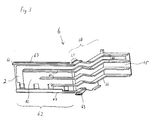
- Fig.1 ein erfindungsgemäßes Schaltgerät und ein benachbart dazu angeordnetes weiteres Schaltgerät im Aufriß;
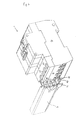
- Fig.2 eine besonders bevorzugte Ausführungsform der Erfindung mit geöffnetem Gehäuse im Aufriß;
- Fig.3 einen erfindungsgemäßen Leitungsträger im Schrägriß;
- Fig.4 das erfindungsgemäße Schaltgerät nach Fig.2 mit geschlossenem Gehäuse im Schrägriß;
- Fig.5a,b eine Deckel für den Träger nach Fig.4 im Schrägriß und im Schnitt;
- Fig.6 eine Seitenansicht des erfindungsgemäßen Schaltgerätes nach Fig.2;
- Fig.7 eine Unteransicht des erfindungsgemäßen Schaltgerätes nach Fig.2;
- Fig.8 das erfindungsgemäße Schaltgerät nach Fig.2 mit einem dazu benachbart anzuordnendem Leitungsschutzschalter im Aufriß;
- Fig.9 die Anordnung nach Fig.8, wobei FI-Modul und LS-Schalter aneinander angerückt sind und der Leitungsträger sich in seiner ausgefahrenden Position befindet und
- Fig.10 die Anordnung nach Fig.9, wobei der Leitungsträger sich in seiner eingefahrenen Position befindet.
- 1 shows a switching device according to the invention and a further switching device arranged adjacent to it in elevation;
- 2 shows a particularly preferred embodiment of the invention with the housing open in elevation;
- 3 shows a cable carrier according to the invention in an oblique view;
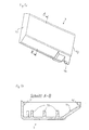
- 4 shows the switching device according to the invention according to Figure 2 with a closed housing in an oblique view;
- 5a, b show a cover for the support according to FIG. 4 in an oblique view and in section;
- 6 shows a side view of the switching device according to the invention according to FIG. 2;
- 7 shows a bottom view of the switching device according to the invention according to FIG. 2;
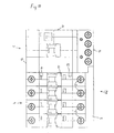
- 8 shows the switching device according to the invention according to FIG. 2 with a circuit breaker to be arranged adjacent to it in elevation;
- 9 shows the arrangement according to FIG. 8, the RCD module and the circuit breaker being moved towards one another and the line carrier being in its extended position, and
- 10 shows the arrangement according to FIG. 9, the line carrier being in its retracted position.
Wie eingangs schon erwähnt, ist es üblich, ein Schaltgerät 1 für Schaltschränke, das mit einem weiteren unmittelbar benachbart angeordneten Schaltgerät 4 elektrisch verbunden werden soll, mit dementsprechenden Leitungen 2 zu versehen, um deren händisches Verlegen zu vermeiden.As already mentioned at the beginning, it is customary to provide a
Diese Maßnahme ist auch bei einem erfindungsgemäßen Schaltgerät 1 vorgesehen, wie am besten aus Fig. 1 ersichtlich ist. Ein Problem, das sich bei einer solchen Anordnung ergibt ist, wie schon erwähnt, daß gleichzeitig mit der elektrischen Verbindung durch die Leitungen 2 auch eine mechanische Verbindung der beiden Schaltgeräte 1,4 hergestellt wird.This measure is also provided in a
Um diese von den Leitungen 2 aufgebaute Verbindung nun ohne Bewegung der beiden Schaltgeräte 1,4 lösen bzw. herstellen zu können -eine Situation, die sich nach dem Montieren der beiden Schaltgeräte 1,4 in einem Schaltschrank zwangsläufig ergibt- ist erfindungsgemäß vorgesehen, die Leitungen 2 relativ zum Schaltgerät 1 längs eines vorbestimmten Weges bewegbar an diesem festzulegen.In order to be able to release or establish this connection established by the
Diese Bewegbarkeit kann beispielsweise dadurch realisiert sein, daß die Leitungen 2 um Achsen 5 verschwenkbar angeordnet sind. Bevorzugt werden die Leitungen 2 jedoch translatorisch verschiebbar, im besonderen parallel zu den Seitenwänden 10,11 des Schaltgerätes 1 verschiebbar gelagert.This movability can be realized, for example, in that the
Prinzipiell könnten die Leitungen 2 jede für sich bewegbar, also verschwenk- oder verschiebbar am Schaltgerät 1 festgelegt sein, aus Gründen der einfacheren Handhabung ist es jedoch günstig, sie gemeinsam bewegbar am Schaltgerät 1 festzulegen. Bevorzugt werden die Leitungen 2 mechanisch miteinander verbunden, wodurch die gemeinsame Bewegbarkeit automatisch gegeben ist. Im Fall der in Fig.1 dargestellten verschwenkbaren Lagerung der Leitungen 2 würden dabei dann die Achsen 5 zu einer gemeinsamen Achse zusammengefaßt werden oder zumindest sämtliche Achsen 5 fluchtend untereinander angeordnet werden. Für die weitere Erklärung wird nun auf ein sehr spezielles Ausführungsbeipiel der Erfindung, das in den Fig.2 bis 10 dargestellt ist, Bezug genommen.In principle, the
Das Schaltgerät 1 ist hierbei als Fehlerstrommodul ausgebildet, welches selbst keine Schaltkontakte sondern lediglich die Fehlerstrom-Erkennungs-Schaltung mit zugehörigem Schaltschloß aufweist. Die Fehlerstrom-Erkennungs-Schaltung ist aus einem Schaltschloß, einem Summenstromwandler 17 und einer das Schaltschloß betätigenden Beschaltung des Summenstromwandlers 17 gebildet. Zur Wahrung der Übersichtlichkeit ist davon in Fig.2 lediglich der Summenstromwandler 17 dargestellt. Das benachbarte Schaltgerät 4 ist ein Leitungsschutzschalter.The
Das Schaltschloß des Fehlerstrommodules weist einen Auslöse-Finger 15 auf, welcher Auslöse-Finger 15 durch die Seitenwand 11 des Fehlerstrommodules sowie durch die Seitenwand 40 des Leitungsschutzschalters hindurchragt und das Schaltschloß des Leitungsschutzschalters betätigen kann (vgl. Fig.8). Damit werden die Schaltkontakte des LS-Schalters sowohl zum Abschalten in Falle einer Leitungsüberlastung als auch beim Auftreten eines Fehlstromes verwendet.The switch lock of the residual current module has a
Die Erfindung ist keineswegs auf diese Ausführungs-Variante beschränkt, vielmehr kann sie auf jede Gattung von in Schaltschränke einbaubare Geräte übertragen werden. Beispiele dafür sind: LS-Schalter mit benachbart angeordnetem FI-Schalter; LS-Schalter mit benachbart angeordnetem Stromstoß-Schalter, Treppenhaus-Automat usw.The invention is in no way limited to this embodiment variant, but rather can be transferred to any type of device which can be installed in control cabinets. Examples of this are: circuit breakers with an adjacent FI switch; Miniature circuit breakers with adjacent impulse switches, staircase automatons, etc.
Wie am besten aus Fig.2 ersichtlich, ist ein Träger 6 vorgesehen, auf welchem die Leitungen 2 angeordnet sind. Der Träger 6 ist parallel zu den Seitenflächen 10,11 des Schaltgerätes 1 zwischen einer eingefahrenen und einer ausgefahrenen Position verschiebbar im Schaltgerät 1 gelagert.As can best be seen from FIG. 2, a
Wesentlichster Bestandteil dieses Trägers 6 ist sein parallel zu den Seitenflächen 10,11 verlaufender Abschnitt 60. Dieser Abschnitt 60 ist ähnlich einer Schublade innerhalb des Schaltgerätes 1 verschiebbar geführt und reicht mit einem Ende 61 durch eine der Schaltgerät-Querwände 12,13 hindurch. Bei der in den Zeichnungen dargestellten Ausführungsform wurde dazu die untere Querwand 12 gewählt, völlig gleichwertig wäre es jedoch, den Träger-Abschnitt 60 durch die obere Querwand 13 durchzuführen.The most important component of this
Am durch die Schaltgerät-Querwand 12 hindurchreichenden Ende 61 des ersten Abschnittes 60 ist ein im wesentlichen normal zu diesem Abschnitt 60 verlaufender zweiter Abschnitt 62 festgelegt. Dieser liegt zur Gänze außerhalb des Schaltgerätes 1 und trägt die Leitungsenden 20. Diese sind so auf dem Träger-Abschnitt 62 verteilt, daß sie bei Bewegung des Trägers 6 in Richtung des Pfeiles 8 in die Anschlußklemmen 3 eines unmittelbar benachbart, also an die Seitenwand 11 angelegt angeordneten weiteren Schaltgerätes 4 hineinreichen.At the end 61 of the
Unter Bezugnahme auf Fig.3 wird nun der Aufbau des Trägers 6 näher erläutert. Der erste Träger-Abschnitt 60 weist weiters an seinem durch die Querwand 12 hindurchragenden Ende 61 einen federnd gehaltenen Ansatz 63 auf. Dieser Ansatz 63 befindet sich in der eingefahrenen Position des Trägers 6 im Inneren des Schaltgerätes 1, ragt in der ausgefahrenen Träger-Position gerade über die Querwand 12 hinaus und kann sich damit an der Kante 64 der Querwand 12 ansetzen (vgl. auch Fig.4). Der Träger 6 ist dadurch in seiner ausgefahrenen Position arretierbar.The structure of the
Der Träger 6 ist durch eine ebene Platte 65 gebildet, an deren Oberflächen die Leitungen 2 festgelegt sind. (Zur Wahrung der Übersichtlichkeit ist in Fig.3 lediglich eine der Leitungen 2 eingezeichnet). Entsprechend der in den Zeichnungen dargestellten Ausführungsform sind dabei sämtliche Leitungen 2 an ein und derselben Oberfläche der Platte 65, nämlich auf der dem weiteren Schaltgerät 4 abgewandten Oberfläche der Platte 65, festgelegt. Es ist im Sinne der Erfindung jedoch auch durchaus möglich, die Leitungen 2 auf beide Oberflächen der Platte 65 zu verteilen, um z.B. bei gleichen Plattenabmessungen Leitungen 2 größeren Querschnittes unterzubringen, oder die Leitungen 2 auf der dem weiteren Schaltgerät 4 abgewandten Oberfläche der Platte 65 anzuordnen.The
Wichtig ist in allen Fällen, daß die Leitungen 2 ausreichend gegeneinander isoliert sind. Dies könnte beispielsweise dadurch realisiert werden, daß die Leitungen 2 mit einem Isoliermaterial, z.B. Kunststoff umgossen werden.It is important in all cases that the
Eine weitere Möglichkeit liegt darin, die Platte 65 an jeder mit Leitungen 2 bestückten Oberfläche mit im wesentlichen normal zu diesen Oberflächen verlaufenden Wandungen 66 auszustatten. Dadurch entstehen einzelne Kammern, in denen die Leitungen 2 -voneinander isoliert- aufgenommen werden.Another possibility is to equip the
Durch diese Art der Isolation ist es nicht notwendig, jede Leitung 2 für sich zu isolieren, vielmehr können blanke Metallbahnen, beispielsweise Kupferbahnen, eingesetzt werden. Damit diese blanken Kupferbahnen nicht auch im Schaltschrank freiliegen, ist ein die Leitungen 2 im Bereich des zweiten Träger-Abschnittes 62 bedeckender Deckel 7 vorgesehen. Zu seiner formschlüssigen Festlegung sind schienenförmige Ansätzen 67 am Träger-Abschnitt 62 und ebenso schienenförmige Ansätze 75 im Deckel 7 selbst angeordnet (vgl. Fig.5a,b).With this type of insulation, it is not necessary to insulate each
An seiner dem Schaltgerät 1 zugewandten Stirnseite 72 ist der Deckel 7 offen, an der dem Schaltgerät 1 abgewandten Stirnseite jedoch von einer Stirnwand 71 verschlossen. Damit kann der Deckel 7 in Richtung des Pfeiles 9 in Fig.2 auf den Träger-Abschnitt 62 aufgeschoben werden.The
An der Innenseite des Deckels 7 sind sich in Richtung der Träger-Platte 65 erstreckende Fortsätze 73 angeordnet. Wie in Fig.6 zu erkennen, sind diese Fortsätze 73 mit einer solchen Höhe ausgebildet, daß sie sich auf die Leitungen 2 abstützen und diese damit zwischen Träger-Platte 65 und Deckel 7 einklemmen.On the inside of the
Im Bereich seiner dem Schaltgerät 1 benachbarten Seitenkante 72 weist der Deckel 7 eine Nase 74 auf, welche Nase 74 in der eingefahrenen Position des Trägers 6 in eine entsprechende Ausnehmung der Schaltgerät-Querwand 12 eingreift (vgl. Fig.7).In the area of its
Damit ist jegliche Verschiebung des Deckels 7 in der eingefahrenen Position des Trägers 6, also nach abgeschlossener Montage verhinderbar und eine zuverlässige Isolation der Leitungen 2 gewährleistet.Any displacement of the
Bei der in den Zeichnungen dargestellten Ausführungsform der Erfindung, wird -wie oben bereits erläutert- die Bewegung des Schaltschloßes des Schaltgerätes 1 durch einen durch die Seitenwand 11 hindurchragenden Auslösefinger 15 auf das Schaltschloß des benachbart angeordneten LS-Schalters übertragen. Damit dieser Auslöse-Finger 15 beim Aneinanderfügen der beiden Schaltgeräte 1,4 exakt in die entsprechende Buchse des LS-Schalter-Schaltschlosses eingeführt werden kann, ist es günstig, die Seitenwand 11, an welche das weitere Schaltgerät 4 anlegbar ist, mit zapfenförmigen Ansätzen 16 zu versehen. Wenn die beiden Schaltgeräte 1,4 volkommen aneinander gerückt sind, so greifen die Ansätze 16 in spiegelbildlich in die Seitenwand des benachbarten Schaltgerätes 4 eingelassene Bohrungen ein und sichern damit eine exakte Ausrichtung der beiden Schaltgeräte 1,4.In the embodiment of the invention shown in the drawings, as already explained above, the movement of the switch lock of the
Anhand der Fig.8-10 wird abschließend die Vorgangsweise bei der Montage eines erfindungsgemäßen FI/LS-Modules erläutert. Das Fehlerstrommodul 1 wird auf der Schaltschrank-Schiene festgelegt (aufgeschnappt) und der Träger 6 in seine ausgefahrene Position gebracht. Der Leitungsschutzschalter 4 wird ebenfalls auf der Schiene -in geringem horizontalen Abstand vom Fehlerstrommodul- angeordnet (Fig.8). Die beiden Schaltgeräte 1,4 werden nun aufeinander zu geschoben, bis die Ansätze 16 in die entsprechenden Bohrungen und der Auslöse-Finger 15 in die entsprechende Buchse eingreift und die Schaltgeräte 1,4 mit ihren Seitenflächen 11,40 aneinander liegen (Fig.9).Finally, the procedure for installing an FI / LS module according to the invention is explained with reference to FIGS. 8-10. The fault
Abschließend wird der Träger 6 in seine eingefahrene Position gebracht, die Leitungsenden 20 damit in die Anschlußklemmen 3 des Leitungsschutzschalters 4 geschoben und die elektrischen Verbindungen durch Anziehen der Anschlußklemmen 3 hergestellt (Fig.10).Finally, the
Claims (16)
Priority Applications (1)
| Application Number | Priority Date | Filing Date | Title |
|---|---|---|---|
| AT97890079T ATE254335T1 (en) | 1996-05-07 | 1997-04-29 | SWITCHING DEVICE WITH MOVABLE CONNECTING CABLES |
Applications Claiming Priority (3)
| Application Number | Priority Date | Filing Date | Title |
|---|---|---|---|
| AT81396 | 1996-05-07 | ||
| AT813/96 | 1996-05-07 | ||
| AT0081396A AT411115B (en) | 1996-05-07 | 1996-05-07 | SWITCHING DEVICE WITH MOVABLE CONNECTING LINES |
Publications (3)
| Publication Number | Publication Date |
|---|---|
| EP0806784A2 true EP0806784A2 (en) | 1997-11-12 |
| EP0806784A3 EP0806784A3 (en) | 1998-05-20 |
| EP0806784B1 EP0806784B1 (en) | 2003-11-12 |
Family
ID=3500323
Family Applications (1)
| Application Number | Title | Priority Date | Filing Date |
|---|---|---|---|
| EP97890079A Expired - Lifetime EP0806784B1 (en) | 1996-05-07 | 1997-04-29 | Switchgear with movable connection lines |
Country Status (10)
| Country | Link |
|---|---|
| EP (1) | EP0806784B1 (en) |
| AT (2) | AT411115B (en) |
| AU (1) | AU715916B2 (en) |
| CZ (1) | CZ293608B6 (en) |
| DE (1) | DE59710978D1 (en) |
| ES (1) | ES2109913T3 (en) |
| GR (1) | GR970300052T1 (en) |
| HU (1) | HU221670B1 (en) |
| PL (1) | PL182547B1 (en) |
| SK (1) | SK283786B6 (en) |
Cited By (11)
| Publication number | Priority date | Publication date | Assignee | Title |
|---|---|---|---|---|
| FR2772979A1 (en) * | 1997-12-18 | 1999-06-25 | Schneider Electric Sa | ELECTRICAL CONNECTION DEVICE OF A DIFFERENTIAL BLOCK ON A CIRCUIT BREAKER OR SIMILAR AND DIFFERENTIAL BLOCK EQUIPPED WITH SUCH A DEVICE |
| FR2779269A1 (en) * | 1998-05-29 | 1999-12-03 | Hager Electro | Coupling device for two attached modular electrical elements |
| EP1100105A1 (en) * | 1999-11-12 | 2001-05-16 | Schneider Electric Industries SA | Wiring method for cicuit breaker |
| EP1278224A1 (en) * | 2001-07-18 | 2003-01-22 | Schneider Electric Industries SAS | Electrical terminal arrangement for two, next to each other, rail-mounted electrical devices |
| DE102005050318B3 (en) * | 2005-10-20 | 2007-03-15 | Siemens Ag | Converter unit used in a device for measuring an electrical differential current comprises a base surface, a clamp holder, a summation current converter and a primary conductor guide with primary conductors |
| EP1770739A1 (en) * | 2005-09-29 | 2007-04-04 | Hager-Electro SAS | Differential unit with inclined trajectory sliding drawer |
| EP2031627A3 (en) * | 2007-08-27 | 2010-09-15 | Phoenix Contact GmbH & Co. KG | Construction unit made of a ground fault circuit breaker and an overvoltage protection device |
| RU2464667C2 (en) * | 2007-07-26 | 2012-10-20 | Бтичино С.П.А. | Device of protection against residual currents for power circuit breaker |
| EP2680379A1 (en) | 2012-06-28 | 2014-01-01 | Schneider Electric Industries SAS | Device for locking at least one modular electric apparatus on a mounting rail, and electric switchgear apparatus fixed onto the rail by means of one such device |
| CN103510768A (en) * | 2013-09-29 | 2014-01-15 | 安徽鑫龙电器股份有限公司 | Breaker door lock mechanism for high-voltage switch cabinet and installation method thereof |
| WO2021164895A1 (en) * | 2020-02-19 | 2021-08-26 | Dehn Se + Co Kg | Overvoltage protection device, overvoltage protection assemblies having an overvoltage protection device of this type, and method for assembling an overvoltage protection assembly |
Families Citing this family (2)
| Publication number | Priority date | Publication date | Assignee | Title |
|---|---|---|---|---|
| ES2155024B1 (en) * | 1999-05-14 | 2001-11-01 | Power Controls Iberica Sl | HOUSING FOR ELECTRICAL DEVICES. |
| US9842715B2 (en) * | 2015-12-04 | 2017-12-12 | Eaton Corporation | Electrical switching apparatus and strain relief assembly therefor |
Family Cites Families (6)
| Publication number | Priority date | Publication date | Assignee | Title |
|---|---|---|---|---|
| DE1145248B (en) * | 1959-12-01 | 1963-03-14 | Stotz Kontakt Gmbh | Terminal arrangement, especially for automatic installation switches |
| DE2654373A1 (en) * | 1976-12-01 | 1978-06-08 | Licentia Gmbh | ERROR CIRCUIT BREAKER COMBINED WITH A MULTIPOLE CIRCUIT BREAKER |
| DE7813854U1 (en) * | 1978-05-08 | 1979-10-11 | Licentia Patent-Verwaltungs-Gmbh, 6000 Frankfurt | Residual current circuit breaker combined with a multi-pole miniature circuit breaker |
| DE8804649U1 (en) * | 1988-04-08 | 1988-06-16 | Murrelektronik GmbH, 7155 Oppenweiler | Electrical device, e.g. switching device, switch-on delay device or similar. |
| FR2640422B1 (en) * | 1988-12-14 | 1996-04-05 | Merlin Gerin | MODULAR ASSEMBLY OF A MULTIPOLAR DIFFERENTIAL CIRCUIT BREAKER |
| FR2711449B1 (en) * | 1993-10-18 | 1995-12-22 | Merlin Gerin | Differential protection block with cable passage. |
-
1996
- 1996-05-07 AT AT0081396A patent/AT411115B/en not_active IP Right Cessation
-
1997
- 1997-04-28 HU HU9700820A patent/HU221670B1/en not_active IP Right Cessation
- 1997-04-29 AT AT97890079T patent/ATE254335T1/en active
- 1997-04-29 DE DE59710978T patent/DE59710978D1/en not_active Expired - Lifetime
- 1997-04-29 EP EP97890079A patent/EP0806784B1/en not_active Expired - Lifetime
- 1997-04-29 ES ES97890079T patent/ES2109913T3/en not_active Expired - Lifetime
- 1997-05-06 CZ CZ19971373A patent/CZ293608B6/en not_active IP Right Cessation
- 1997-05-07 SK SK580-97A patent/SK283786B6/en not_active IP Right Cessation
- 1997-05-07 AU AU20095/97A patent/AU715916B2/en not_active Ceased
- 1997-05-07 PL PL97319846A patent/PL182547B1/en not_active IP Right Cessation
- 1997-12-31 GR GR970300052T patent/GR970300052T1/en unknown
Cited By (20)
| Publication number | Priority date | Publication date | Assignee | Title |
|---|---|---|---|---|
| FR2772979A1 (en) * | 1997-12-18 | 1999-06-25 | Schneider Electric Sa | ELECTRICAL CONNECTION DEVICE OF A DIFFERENTIAL BLOCK ON A CIRCUIT BREAKER OR SIMILAR AND DIFFERENTIAL BLOCK EQUIPPED WITH SUCH A DEVICE |
| EP0926695A1 (en) * | 1997-12-18 | 1999-06-30 | Schneider Electric Sa | Electrical connection device of a differential unit to a circuit breaker or similar and a differential unit equiped with such a device |
| TR199802642A3 (en) * | 1997-12-18 | 1999-10-21 | Schneider Electric S.A. | A device for electrical connection of a differential unit to a circuit breaker or similar device and a differential unit equipped with such a device. |
| FR2779269A1 (en) * | 1998-05-29 | 1999-12-03 | Hager Electro | Coupling device for two attached modular electrical elements |
| WO1999063563A1 (en) * | 1998-05-29 | 1999-12-09 | Hager Electro | Device for coupling two attached modular electrical elements |
| AU741444B2 (en) * | 1998-05-29 | 2001-11-29 | Hager Electro | Device for coupling two attached modular electrical elements |
| EP1100105A1 (en) * | 1999-11-12 | 2001-05-16 | Schneider Electric Industries SA | Wiring method for cicuit breaker |
| FR2801165A1 (en) * | 1999-11-12 | 2001-05-18 | Schneider Electric Ind Sa | PRE-CABLE DEVICE FOR CONTACTORS |
| US6388894B1 (en) | 1999-11-12 | 2002-05-14 | Schneider Electric Industries Sa | Pre-wiring device for contactors |
| FR2827702A1 (en) * | 2001-07-18 | 2003-01-24 | Schneider Electric Ind Sa | DEVICE FOR ELECTRICALLY CONNECTING TWO SIDE BY SIDE ELECTRICAL APPLIANCES ON THE SAME MOUNTING SUPPORT |
| EP1278224A1 (en) * | 2001-07-18 | 2003-01-22 | Schneider Electric Industries SAS | Electrical terminal arrangement for two, next to each other, rail-mounted electrical devices |
| EP1770739A1 (en) * | 2005-09-29 | 2007-04-04 | Hager-Electro SAS | Differential unit with inclined trajectory sliding drawer |
| DE102005050318B3 (en) * | 2005-10-20 | 2007-03-15 | Siemens Ag | Converter unit used in a device for measuring an electrical differential current comprises a base surface, a clamp holder, a summation current converter and a primary conductor guide with primary conductors |
| RU2464667C2 (en) * | 2007-07-26 | 2012-10-20 | Бтичино С.П.А. | Device of protection against residual currents for power circuit breaker |
| EP2031627A3 (en) * | 2007-08-27 | 2010-09-15 | Phoenix Contact GmbH & Co. KG | Construction unit made of a ground fault circuit breaker and an overvoltage protection device |
| EP2680379A1 (en) | 2012-06-28 | 2014-01-01 | Schneider Electric Industries SAS | Device for locking at least one modular electric apparatus on a mounting rail, and electric switchgear apparatus fixed onto the rail by means of one such device |
| FR2992783A1 (en) * | 2012-06-28 | 2014-01-03 | Schneider Electric Ind Sas | DEVICE FOR LOCKING AT LEAST ONE MODULAR ELECTRICAL APPARATUS ON A MOUNTING RAIL, AND ELECTRICAL CUTTING APPARATUS ATTACHED TO THE RAIL USING SUCH A DEVICE |
| CN103515845A (en) * | 2012-06-28 | 2014-01-15 | 施耐德电器工业公司 | Device for locking electric apparatus on guide rail, and electric switchgear apparatus |
| CN103510768A (en) * | 2013-09-29 | 2014-01-15 | 安徽鑫龙电器股份有限公司 | Breaker door lock mechanism for high-voltage switch cabinet and installation method thereof |
| WO2021164895A1 (en) * | 2020-02-19 | 2021-08-26 | Dehn Se + Co Kg | Overvoltage protection device, overvoltage protection assemblies having an overvoltage protection device of this type, and method for assembling an overvoltage protection assembly |
Also Published As
| Publication number | Publication date |
|---|---|
| ATA81396A (en) | 2003-02-15 |
| PL319846A1 (en) | 1997-11-10 |
| AU2009597A (en) | 1997-11-13 |
| HU221670B1 (en) | 2002-12-28 |
| HUP9700820A2 (en) | 1998-01-28 |
| ES2109913T3 (en) | 2004-07-01 |
| CZ137397A3 (en) | 1998-12-16 |
| CZ293608B6 (en) | 2004-06-16 |
| AT411115B (en) | 2003-09-25 |
| ES2109913T1 (en) | 1998-02-01 |
| EP0806784A3 (en) | 1998-05-20 |
| ATE254335T1 (en) | 2003-11-15 |
| SK283786B6 (en) | 2004-01-08 |
| GR970300052T1 (en) | 1997-12-31 |
| DE59710978D1 (en) | 2003-12-18 |
| AU715916B2 (en) | 2000-02-10 |
| PL182547B1 (en) | 2002-01-31 |
| HU9700820D0 (en) | 1997-06-30 |
| HUP9700820A3 (en) | 1999-11-29 |
| EP0806784B1 (en) | 2003-11-12 |
| SK58097A3 (en) | 1998-07-08 |
Similar Documents
| Publication | Publication Date | Title |
|---|---|---|
| EP0709920B1 (en) | Modular control system | |
| EP0899818B1 (en) | Electric terminal, in particular for use with printed circuit boards | |
| AT411115B (en) | SWITCHING DEVICE WITH MOVABLE CONNECTING LINES | |
| EP1914838A1 (en) | Modular installation switching device | |
| DD292105A5 (en) | SWITCHING DEVICE WITH PROTECTED INTERRUPTORS | |
| EP1856709B1 (en) | Electromechanical switching device | |
| DE4124487C2 (en) | adapter | |
| EP0133152A1 (en) | Arrangement for the connection of auxiliary conductors to a switchgear or a switchgear combination | |
| DE2515152B2 (en) | Electrical switchgear for low voltage | |
| DE69420923T2 (en) | Differential protection block with cable passage | |
| EP1851839B1 (en) | Switchgear | |
| DE4312617C2 (en) | Electrical control panel, especially for medium voltage systems | |
| EP0821454B1 (en) | Connecting device for electrical installation apparatus | |
| EP1784847B1 (en) | Electric installation device | |
| DE102004037083A1 (en) | Surge arrester arrangement with an executable as part of a housing support plate | |
| EP2786389B1 (en) | Permanent magnet assembly for an arc driver assembly and switching device | |
| EP0223732B1 (en) | Multipole low-voltage power circuit breaker with current bars | |
| DE10003349A1 (en) | Holding device for fastening at least one electrical switching device on a top-hat rail | |
| DE4337254B4 (en) | Fault current module, which can be assembled with circuit breakers | |
| DE10146503A1 (en) | Electrical installation distribution | |
| DE69607136T2 (en) | Control panel and connection device for electrical installations with modular devices | |
| DE102005049873A1 (en) | Over voltage protection arrangement for low voltage system, has coupler shaped unit for electrical and mechanical connection for direct assembly on bus bar system with bus bars at or in lower side of carrier plate in grid spacing of system | |
| DE10106270A1 (en) | Device unit with a contact device for detachable connection to fixed power rails | |
| DE102012215528B4 (en) | Switches, in particular circuit breakers for low voltages | |
| DE69808836T2 (en) | Adapter for modular connection of electrical devices to an electrical distribution system based on rails |
Legal Events
| Date | Code | Title | Description |
|---|---|---|---|
| PUAI | Public reference made under article 153(3) epc to a published international application that has entered the european phase |
Free format text: ORIGINAL CODE: 0009012 |
|
| AK | Designated contracting states |
Kind code of ref document: A2 Designated state(s): AT BE CH DE DK ES FI FR GB GR IE IT LI LU MC NL PT SE |
|
| AX | Request for extension of the european patent |
Free format text: AL PAYMENT 970530;LT PAYMENT 970530;LV PAYMENT 970530;RO PAYMENT 970530;SI PAYMENT 970530 |
|
| ITCL | It: translation for ep claims filed |
Representative=s name: SAMA DANIELE |
|
| EL | Fr: translation of claims filed | ||
| IECL | Ie: translation for ep claims filed | ||
| REG | Reference to a national code |
Ref country code: ES Ref legal event code: BA2A Ref document number: 2109913 Country of ref document: ES Kind code of ref document: T1 |
|
| TCNL | Nl: translation of patent claims filed | ||
| PUAL | Search report despatched |
Free format text: ORIGINAL CODE: 0009013 |
|
| GBC | Gb: translation of claims filed (gb section 78(7)/1977) | ||
| AK | Designated contracting states |
Kind code of ref document: A3 Designated state(s): AT BE CH DE DK ES FI FR GB GR IE IT LI LU MC NL PT SE |
|
| AX | Request for extension of the european patent |
Free format text: AL PAYMENT 970530;LT PAYMENT 970530;LV PAYMENT 970530;RO PAYMENT 970530;SI PAYMENT 970530 |
|
| 17P | Request for examination filed |
Effective date: 19981120 |
|
| 17Q | First examination report despatched |
Effective date: 20020606 |
|
| GRAH | Despatch of communication of intention to grant a patent |
Free format text: ORIGINAL CODE: EPIDOS IGRA |
|
| GRAS | Grant fee paid |
Free format text: ORIGINAL CODE: EPIDOSNIGR3 |
|
| GRAA | (expected) grant |
Free format text: ORIGINAL CODE: 0009210 |
|
| AK | Designated contracting states |
Kind code of ref document: B1 Designated state(s): AT BE CH DE DK ES FI FR GB GR IE IT LI LU MC NL PT SE |
|
| AX | Request for extension of the european patent |
Extension state: AL LT LV RO SI |
|
| PG25 | Lapsed in a contracting state [announced via postgrant information from national office to epo] |
Ref country code: NL Free format text: LAPSE BECAUSE OF FAILURE TO SUBMIT A TRANSLATION OF THE DESCRIPTION OR TO PAY THE FEE WITHIN THE PRESCRIBED TIME-LIMIT Effective date: 20031112 Ref country code: IE Free format text: LAPSE BECAUSE OF FAILURE TO SUBMIT A TRANSLATION OF THE DESCRIPTION OR TO PAY THE FEE WITHIN THE PRESCRIBED TIME-LIMIT Effective date: 20031112 Ref country code: GB Free format text: LAPSE BECAUSE OF FAILURE TO SUBMIT A TRANSLATION OF THE DESCRIPTION OR TO PAY THE FEE WITHIN THE PRESCRIBED TIME-LIMIT Effective date: 20031112 Ref country code: FI Free format text: LAPSE BECAUSE OF FAILURE TO SUBMIT A TRANSLATION OF THE DESCRIPTION OR TO PAY THE FEE WITHIN THE PRESCRIBED TIME-LIMIT Effective date: 20031112 |
|
| REG | Reference to a national code |
Ref country code: GB Ref legal event code: FG4D Free format text: NOT ENGLISH |
|
| REG | Reference to a national code |
Ref country code: CH Ref legal event code: EP |
|
| REF | Corresponds to: |
Ref document number: 59710978 Country of ref document: DE Date of ref document: 20031218 Kind code of ref document: P |
|
| REG | Reference to a national code |
Ref country code: IE Ref legal event code: FG4D Free format text: GERMAN |
|
| PG25 | Lapsed in a contracting state [announced via postgrant information from national office to epo] |
Ref country code: SE Free format text: LAPSE BECAUSE OF FAILURE TO SUBMIT A TRANSLATION OF THE DESCRIPTION OR TO PAY THE FEE WITHIN THE PRESCRIBED TIME-LIMIT Effective date: 20040212 Ref country code: GR Free format text: LAPSE BECAUSE OF FAILURE TO SUBMIT A TRANSLATION OF THE DESCRIPTION OR TO PAY THE FEE WITHIN THE PRESCRIBED TIME-LIMIT Effective date: 20040212 Ref country code: DK Free format text: LAPSE BECAUSE OF FAILURE TO SUBMIT A TRANSLATION OF THE DESCRIPTION OR TO PAY THE FEE WITHIN THE PRESCRIBED TIME-LIMIT Effective date: 20040212 |
|
| LTIE | Lt: invalidation of european patent or patent extension |
Effective date: 20031112 |
|
| PG25 | Lapsed in a contracting state [announced via postgrant information from national office to epo] |
Ref country code: LU Free format text: LAPSE BECAUSE OF NON-PAYMENT OF DUE FEES Effective date: 20040429 |
|
| PG25 | Lapsed in a contracting state [announced via postgrant information from national office to epo] |
Ref country code: MC Free format text: LAPSE BECAUSE OF NON-PAYMENT OF DUE FEES Effective date: 20040430 Ref country code: LI Free format text: LAPSE BECAUSE OF NON-PAYMENT OF DUE FEES Effective date: 20040430 Ref country code: CH Free format text: LAPSE BECAUSE OF NON-PAYMENT OF DUE FEES Effective date: 20040430 |
|
| NLV1 | Nl: lapsed or annulled due to failure to fulfill the requirements of art. 29p and 29m of the patents act | ||
| GBV | Gb: ep patent (uk) treated as always having been void in accordance with gb section 77(7)/1977 [no translation filed] |
Effective date: 20031112 |
|
| REG | Reference to a national code |
Ref country code: ES Ref legal event code: FG2A Ref document number: 2109913 Country of ref document: ES Kind code of ref document: T3 |
|
| ET | Fr: translation filed | ||
| PLBE | No opposition filed within time limit |
Free format text: ORIGINAL CODE: 0009261 |
|
| STAA | Information on the status of an ep patent application or granted ep patent |
Free format text: STATUS: NO OPPOSITION FILED WITHIN TIME LIMIT |
|
| 26N | No opposition filed |
Effective date: 20040813 |
|
| REG | Reference to a national code |
Ref country code: CH Ref legal event code: PL |
|
| PG25 | Lapsed in a contracting state [announced via postgrant information from national office to epo] |
Ref country code: PT Free format text: LAPSE BECAUSE OF NON-PAYMENT OF DUE FEES Effective date: 20040412 |
|
| PGFP | Annual fee paid to national office [announced via postgrant information from national office to epo] |
Ref country code: BE Payment date: 20120516 Year of fee payment: 16 |
|
| PGFP | Annual fee paid to national office [announced via postgrant information from national office to epo] |
Ref country code: AT Payment date: 20120327 Year of fee payment: 16 |
|
| BERE | Be: lapsed |
Owner name: *FELTEN & GUILLEAUME AUSTRIA A.G. Effective date: 20130430 |
|
| REG | Reference to a national code |
Ref country code: AT Ref legal event code: MM01 Ref document number: 254335 Country of ref document: AT Kind code of ref document: T Effective date: 20130430 |
|
| PG25 | Lapsed in a contracting state [announced via postgrant information from national office to epo] |
Ref country code: BE Free format text: LAPSE BECAUSE OF NON-PAYMENT OF DUE FEES Effective date: 20130430 Ref country code: AT Free format text: LAPSE BECAUSE OF NON-PAYMENT OF DUE FEES Effective date: 20130430 |
|
| REG | Reference to a national code |
Ref country code: FR Ref legal event code: PLFP Year of fee payment: 19 |
|
| REG | Reference to a national code |
Ref country code: FR Ref legal event code: PLFP Year of fee payment: 20 |
|
| PGFP | Annual fee paid to national office [announced via postgrant information from national office to epo] |
Ref country code: FR Payment date: 20160331 Year of fee payment: 20 |
|
| PGFP | Annual fee paid to national office [announced via postgrant information from national office to epo] |
Ref country code: ES Payment date: 20160411 Year of fee payment: 20 Ref country code: DE Payment date: 20160414 Year of fee payment: 20 |
|
| PGFP | Annual fee paid to national office [announced via postgrant information from national office to epo] |
Ref country code: IT Payment date: 20160414 Year of fee payment: 20 |
|
| REG | Reference to a national code |
Ref country code: DE Ref legal event code: R071 Ref document number: 59710978 Country of ref document: DE |
|
| REG | Reference to a national code |
Ref country code: ES Ref legal event code: FD2A Effective date: 20170804 |
|
| PG25 | Lapsed in a contracting state [announced via postgrant information from national office to epo] |
Ref country code: ES Free format text: LAPSE BECAUSE OF EXPIRATION OF PROTECTION Effective date: 20170430 |