EP0806573B1 - Flüssigkeitssteuervorrichtung - Google Patents
Flüssigkeitssteuervorrichtung Download PDFInfo
- Publication number
- EP0806573B1 EP0806573B1 EP97107532A EP97107532A EP0806573B1 EP 0806573 B1 EP0806573 B1 EP 0806573B1 EP 97107532 A EP97107532 A EP 97107532A EP 97107532 A EP97107532 A EP 97107532A EP 0806573 B1 EP0806573 B1 EP 0806573B1
- Authority
- EP
- European Patent Office
- Prior art keywords
- subchannel
- channel
- process gas
- fluid
- gas
- Prior art date
- Legal status (The legal status is an assumption and is not a legal conclusion. Google has not performed a legal analysis and makes no representation as to the accuracy of the status listed.)
- Expired - Lifetime
Links
Images


Classifications
-
- H—ELECTRICITY
- H10—SEMICONDUCTOR DEVICES; ELECTRIC SOLID-STATE DEVICES NOT OTHERWISE PROVIDED FOR
- H10P—GENERIC PROCESSES OR APPARATUS FOR THE MANUFACTURE OR TREATMENT OF DEVICES COVERED BY CLASS H10
- H10P72/00—Handling or holding of wafers, substrates or devices during manufacture or treatment thereof
- H10P72/04—Apparatus for manufacture or treatment
- H10P72/0402—Apparatus for fluid treatment
- H10P72/0406—Apparatus for fluid treatment for cleaning followed by drying, rinsing, stripping, blasting or the like
- H10P72/0408—Apparatus for fluid treatment for cleaning followed by drying, rinsing, stripping, blasting or the like for drying
-
- F—MECHANICAL ENGINEERING; LIGHTING; HEATING; WEAPONS; BLASTING
- F16—ENGINEERING ELEMENTS AND UNITS; GENERAL MEASURES FOR PRODUCING AND MAINTAINING EFFECTIVE FUNCTIONING OF MACHINES OR INSTALLATIONS; THERMAL INSULATION IN GENERAL
- F16K—VALVES; TAPS; COCKS; ACTUATING-FLOATS; DEVICES FOR VENTING OR AERATING
- F16K27/00—Construction of housing; Use of materials therefor
- F16K27/003—Housing formed from a plurality of the same valve elements
-
- H—ELECTRICITY
- H10—SEMICONDUCTOR DEVICES; ELECTRIC SOLID-STATE DEVICES NOT OTHERWISE PROVIDED FOR
- H10P—GENERIC PROCESSES OR APPARATUS FOR THE MANUFACTURE OR TREATMENT OF DEVICES COVERED BY CLASS H10
- H10P14/00—Formation of materials, e.g. in the shape of layers or pillars
- H10P14/60—Formation of materials, e.g. in the shape of layers or pillars of insulating materials
- H10P14/65—Formation of materials, e.g. in the shape of layers or pillars of insulating materials characterised by treatments performed before or after the formation of the materials
- H10P14/6502—Formation of materials, e.g. in the shape of layers or pillars of insulating materials characterised by treatments performed before or after the formation of the materials of treatments performed before formation of the materials
- H10P14/6512—Formation of materials, e.g. in the shape of layers or pillars of insulating materials characterised by treatments performed before or after the formation of the materials of treatments performed before formation of the materials by exposure to a gas or vapour
-
- H—ELECTRICITY
- H10—SEMICONDUCTOR DEVICES; ELECTRIC SOLID-STATE DEVICES NOT OTHERWISE PROVIDED FOR
- H10P—GENERIC PROCESSES OR APPARATUS FOR THE MANUFACTURE OR TREATMENT OF DEVICES COVERED BY CLASS H10
- H10P70/00—Cleaning of wafers, substrates or parts of devices
- H10P70/10—Cleaning before device manufacture, i.e. Begin-Of-Line process
- H10P70/12—Cleaning before device manufacture, i.e. Begin-Of-Line process by dry cleaning only
-
- Y—GENERAL TAGGING OF NEW TECHNOLOGICAL DEVELOPMENTS; GENERAL TAGGING OF CROSS-SECTIONAL TECHNOLOGIES SPANNING OVER SEVERAL SECTIONS OF THE IPC; TECHNICAL SUBJECTS COVERED BY FORMER USPC CROSS-REFERENCE ART COLLECTIONS [XRACs] AND DIGESTS
- Y10—TECHNICAL SUBJECTS COVERED BY FORMER USPC
- Y10T—TECHNICAL SUBJECTS COVERED BY FORMER US CLASSIFICATION
- Y10T137/00—Fluid handling
- Y10T137/4238—With cleaner, lubrication added to fluid or liquid sealing at valve interface
- Y10T137/4245—Cleaning or steam sterilizing
- Y10T137/4259—With separate material addition
-
- Y—GENERAL TAGGING OF NEW TECHNOLOGICAL DEVELOPMENTS; GENERAL TAGGING OF CROSS-SECTIONAL TECHNOLOGIES SPANNING OVER SEVERAL SECTIONS OF THE IPC; TECHNICAL SUBJECTS COVERED BY FORMER USPC CROSS-REFERENCE ART COLLECTIONS [XRACs] AND DIGESTS
- Y10—TECHNICAL SUBJECTS COVERED BY FORMER USPC
- Y10T—TECHNICAL SUBJECTS COVERED BY FORMER US CLASSIFICATION
- Y10T137/00—Fluid handling
- Y10T137/8593—Systems
- Y10T137/87571—Multiple inlet with single outlet
- Y10T137/87676—With flow control
- Y10T137/87684—Valve in each inlet
Definitions
- the present invention relates to a method for operating a fluid control device according to the preamble of claim 1 and an apparatus for producing semiconductors according to the preamble of claim 2.
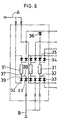
- FIG. 6 shows a fluid control device for use in apparatus for producing semiconductors.
- the device consists of a plurality of lines each comprising a massflow controller 31, two inlet on-off valves 32, 33 provided at the inlet side of the controller 31, and two or three outlet on-off valves 34, 35, 36 arranged at the outlet side of the controller.
- the inlet on-off valves 32, 33 are used for selectively supplying one of two kinds of gases, i.e., process gas A and purge gas B, while the outlet on-off valves 34, 35, 36 are provided for a line leading to a process chamber, a vent line and an evacuating line for a change-over from one line to another.
- Process gas A is a gas of which high purity is required and which is expensive.
- Such a fluid control device has channels for passing the gases A and B, i.e., a main channel 37 in communication with the inlet of a channel within the massflow controller 31, a relatively long subchannel 38 and a relatively short subchannel 39.
- the relatively short subchannel 39 is thought useful for passing process gas A to be assured of high purity in ensuring the purity of process gas A and reducing the amount thereof to be used.
- An object of the present invention is to provide a method and apparatus of the above mentioned kind which are optimized in ensuring the purity of the fluid, such as process gas, to be assured of high purity and in reducing the amount thereof to be used, by introducing the concept of a minimized dead volume (stagnant portion of fluid) in connection with the fluid of which high purity is required.
- the fluid to be assured of high purity is the process gas, and the fluid which is the second in the order of importance of ensuring purity is the purge gas.
- the dead volume involved in passing the fluid to be assured of high purity is smaller in the fluid control device of the invention than in the conventional devices. This diminishes the reduction of purity occurring in starting to pass the fluid of which high purity is required. Accordingly the present device produces optimized effects in ensuring the purity of the fluid to be assured of high purity and in. reducing the amount of the fluid to be used.
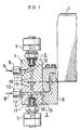
- FIG. 1 shows an embodiment of fluid control device in which the method of the present invention can be performed.
- Two on-off valves 2, 3 are provided at the inlet side of a massflow controller 1 and positioned one above the other as opposed to each other.
- the upper on-off valve 2 and the lower on-off valve 3 have their main bodies 4, 5 joined to each other.
- An actuator 6 for the upper on-off valve 2 is mounted on the top of the valve main body 4, while an actuator 7 for the lower on-off valve 3 is attached to the bottom of the valve main body 5.
- the main body 5 of the lower on-off valve 3 is joined to a channel block 8 provided at the inlet side of the massflow controller 1.
- the upper and lower valve main bodies 4, 5 are provided with inlet pipe joints 9, 10, respectively.
- the upper valve main body 4 is formed with an L-shaped inflow channel 11 and an I-shaped outflow channel 12.
- the outflow channel 12 is downwardly opened.
- the lower valve main body 5 is formed with an inverted L-shaped inflow channel 13 symmetric with the L-shaped inflow channel 11 of the upper valve main body 4, a reverse L-shaped outflow channel 14 generally symmetric with the inflow channel 13, and a bypass channel 15 holding the outflow channel 14 in communication with the outflow channel 12 of the upper valve main body 4.
- the reverse L-shaped outflow channel 14 of the lower valve main body 5 comprises a main channel 16 communicating with the controller 1 for regulating the pressure or flow rate of a fluid, and a subchannel 17 communicating with the main channel 16 and connected to the inflow channel 13 by the lower valve actuator 7.
- the main channel 16 is used not only as an outflow channel for the fluid to be admitted through the lower inlet pipe joint 10 but also as the outflow channel for the fluid to be admitted via the upper inlet pipe joint 9.
- the fluid control device has a relatively long subchannel 18 comprising the outflow channel 12 of the upper valve main body 4 and the bypass channel 15 of the lower valve main body 5, and the subchannel 17 which is relatively short and which provides part of the outflow channel 14.
- Process gas A is passed through the relatively long subchannel 18, and purge gas B through the relatively short subchannel 17.
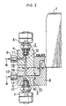
- FIG. 2 shows a fluid control device which comprises the same components as in FIG. 1 and which differs from the device of FIG. 1 only in that purge gas B is passed through a relatively long subchannel 18, with process gas A passed through a relatively short subchannel 17.
- the dead volume involved in passing fluid A to be assured of high purity is only. the portion of the relative short subchannel 17 indicated by dotting in FIG. 1.
- the dead volume involved in passing the fluid to be assured of high purity is the portion of the relatively long subchannel 18 indicated by dotting in FIG. 2.
- FIG. 3 shows variations in the purity of process gas after the start of passage of the gas through the fluid control device shown in FIG. 1. More specifically, the purity of the process gas was determined by checking N 2 , serving as a purge gas, for the reduction of concentration. The gas flow rate for testing was 20 c.c./min. With reference to the drawing, the concentration of N 2 decreased to 5 ppb, i.e., to a background level, during a replacement time of 90 seconds. This indicates that 90 seconds after the start of replacement, the purity of process gas reached a high level for use in the fabrication of semiconductors.
- N 2 serving as a purge gas
- FIG. 4 shows variations in the purity of process gas after the start of passage of the gas through the conventional fluid control device shown in FIG. 2.
- the replacement time was more than 1650 seconds, and the reduced concentration of N 2 still remained as high as 1 ppm even after the lapse of about 30 minutes. This indicates that the process gas of low purity must be used in the meantime or needs to be discarded.
- the dead volume was 0.05 c.c. in the device of FIG. 1 and 0.67 c.c. in the device of FIG. 2.
- Two on-off valves are provided at the outlet side of the massflow controller 1 for a change-over from a line leading to a process chamber to a vent line and vice versa . Based on the same concept as above, a relatively long subchannel is used for the line leading to the process chamber.
- valve main bodies 4, 5 and actuators 6, 7 described are merely an example; such components are usable in a suitably altered combination.
- the two valve main bodies 4, 5 may be combined into an integral body or arranged side by side instead of being positioned one above the other.
- the valve main bodies, as well as the valve actuators, may be three in number. FIG. 5 shows such an example.
- a massflow controller 1 is provided at the outlet side thereof with a valve device 21 comprising a valve main body 22 and three valve actuators 23, 24, 25.
- the valve main body 22 has formed therein a straight channel 26 extending straight from a channel in a channel block 8 disposed at the outlet side of the massflow controller 1.
- the straight channel 26 includes a portion extending from its end adjacent to the block 8 to the actuator 25 most proximate to the massflow controller 1 and serving as a main channel 26a.
- the shortest subchannel 27 is a portion extending from the main channel 26a to the actuator 25 most proximate to the controller 1.
- the subchannel 28, 26b of an intermediate length comprises a portion 26b included in the straight channel 26 and extending between the middle actuator 24 and the actuator 25 most proximate to the controller 1, and a portion 28 extending from the straight channel 26 to the middle actuator 24.
- The. longest subchannel 29, 26c, 26b comprises a portion 26c, 26b included in the straight channel 26 and extending between the actuator 23 remotest from the controller 1 and the actuator 25 most proximate to the controller 1, and a channel 29 extending from the straight channel 26 to the actuator 23 remotest from the controller 1.
- the longest subchannel 29, 26c, 26b serves as a line leading to a process gas chamber, the subchannel 28, 26b of intermediate length as a vent line, and the shortest subchannel 27 as an evacuating line.
- the dead volume of the line leading to the process gas chamber is the combination of the shortest subchannel 27 interconnecting the main channel 26a and the actuator 25 most proximate to the controller 1 and the portion 28 interconnecting the straight channel 26 and the middle actuator 24.
- the dead volume of the vent line is the combination of the shortest subchannel 27 interconnecting the main channel 26a and the actuator 25 most proximate to the controller 1, portion 26c included in the straight channel 26 and extending between the actuator 23 remotest from the controller 1 and the middle actuator 24 and the channel 29 interconnecting the straight channel 26 and the actuator 23 remotest from the controller 1.
- the dead volume of the evacuating line is the combination of the longest subchannel 29, 26c, 26b and the portion 28 interconnecting the straight channel 26 and the middle actuator 24.
- the process gas chamber line provided by the longest subchannel 29, 26c, 26b with the smallest dead volume achieves optimized results in ensuring the purity of the process gas and reducing the amount of the gas to be used on the same principle as previously stated. Since the evacuating line is used for removing air to a vacuum, no problem whatever will arise even if the dead volume of the evacuating line is great. It is desired that the subchannel 28, 26b of intermediate length provide the vent line so as to reduce the dead volume of this line.
- the fluid control device comprises a valve main body having formed therein a main channel in communication with an inlet or outlet of a channel within a controller for regulating the pressure or flow rate of fluids, and a relatively long subchannel and a relatively short subchannel both communicating with the main channel, one of the subchannels being serviceable for the fluid to be assured of high purity.
- the relatively long subchannel is used for passing this fluid, the device achieves optimized results in ensuring the high purity of the fluid and in reducing the amount of the fluid to be used.
- the longest subchannel is used for the fluid which is the first in the order of importance of ensuring high purity, and the longer of the remaining two subchannels is used for another fluid which is the second in the order of importance.
Landscapes
- Engineering & Computer Science (AREA)
- General Engineering & Computer Science (AREA)
- Mechanical Engineering (AREA)
- Valve Housings (AREA)
- Pipeline Systems (AREA)
- Fluid-Pressure Circuits (AREA)
- Lift Valve (AREA)
- Flow Control (AREA)
Claims (2)
- Verfahren zum Betreiben einer Fluidsteuervorrichtung, um ein Prozeßgas (A), bei dem eine hohe Reinheit sichergestellt werden soll, und ein Reinigungsgas (B) einem Kanal in einer Steuerung (1) zum Regulieren des Drucks oder der Flußrate von Fluiden zuzuführen, wobei die Fluidsteuervorrichtung einen Ventilhauptkörper (4, 5), der einen Hauptkanal (16), welcher mit einem Einlaß oder einem Auslaß des Kanals in der Steuerung (1) verbindbar ist, einen ersten Nebenkanal (18), welcher mit dem Hauptkanal (16) verbunden ist, und einen zweiten Nebenkanal (17), welcher auch mit dem Hauptkanal (16) verbunden ist, hat, ein erstes Ventilbetätigungselement (6) zum Öffnen und Schließen des ersten Nebenkanals (18) für den Durchfluß des Fluids und ein zweites Ventilbetätigungselement (7) zum Öffnen und Schließen des zweiten Nebenkanals (17) für den Durchfluß des Fluids aufweist, wobei das Verfahren die Schritte umfaßt, daß:dadurch gekennzeichnet, daß das Volumen des zweiten Nebenkanals (17), durch welchen das Reinigungsgas (B) zugeführt wird, kleiner als das Volumen des ersten Nebenkanals (18), durch welchen das Prozeßgas (A) zugeführt wird, ist.a) der erste Nebenkanal (18) geöffnet wird und der zweite Nebenkanal (17) geschlossen wird,b) das Prozeßgas (A) durch das erste Betätigungselement (6) und den ersten Nebenkanal (18) zu dem Hauptkanal (16) geführt wird, wobei der Totraum, der beim Zuführen des Prozeßgases (A) zu dem Hauptkanal (16) auftritt, das Volumen des zweiten Nebenkanals (17) ist,c) der erste Nebenkanal (18) geschlossen wird und der zweite Nebenkanal (17) geöffnet wird, undd) das Reinigungsgas (B) durch das zweite Betätigungselement (7) und den zweiten Nebenkanal (17) dem Hauptkanal (16) zugeführt wird, wobei der Totraum, der beim Zuführen des Reinigungsgases (B) zu dem Kanal (16) auftritt, das Volumen des ersten Nebenkanals (18) ist,
- Vorrichtung zur Halbleiterproduktion mit einer Prozeßgasleitung (A) für die Zuführung eines Prozeßgases, bei dem eine hohe Reinheit sichergestellt werden soll, einer Reinigungsgasleitung (B) für die Zuführung eines Reinigungsgases, einer Steuerung zum Regulieren des Druckes oder der Flußrate des Gases und einer Fluidsteuervorrichtung, die einen Ventilhauptkörper (4; 5) aufweist, der einen Hauptkanal (16), welcher mit einem Einlaß oder einem Auslaß der Steuerung (1) verbunden ist, einen ersten Nebenkanal (18), welcher an seinem einen Ende mit dem Hauptkanal (16) verbunden ist und an seinem anderen Ende über ein erstes Ventilbetätigungselement (6) mit der Prozeßgasleitung (A) verbunden ist, und einen zweiten Nebenkanal (17), welcher auch an seinem einen Ende mit dem Hauptkanal (16) und an seinem anderen Ende über ein zweites Ventilbetätigungselement (7) mit der Reinigungsgasleitung (B) verbunden ist, hat, wobei die Betätigungselemente (6) und (7) zum Öffnen und Schließen der Nebenkanäle (18 und 17) für den Durchlaß des Gases betätigbar sind, dadurch gekennzeichnet, daß das Volumen des zweiten Nebenkanals (17), durch welchen das Reinigungsgas geleitet wird, kleiner als das Volumen des ersten Nebenkanals (18), durch welchen das Prozeßgas geleitet wird, ist.
Priority Applications (1)
| Application Number | Priority Date | Filing Date | Title |
|---|---|---|---|
| EP02018943A EP1276030A3 (de) | 1996-05-10 | 1997-05-07 | Fluidsteuervorrichtung |
Applications Claiming Priority (3)
| Application Number | Priority Date | Filing Date | Title |
|---|---|---|---|
| JP116204/96 | 1996-05-10 | ||
| JP11620496A JP3726168B2 (ja) | 1996-05-10 | 1996-05-10 | 流体制御装置 |
| JP11620496 | 1996-05-10 |
Related Child Applications (1)
| Application Number | Title | Priority Date | Filing Date |
|---|---|---|---|
| EP02018943A Division EP1276030A3 (de) | 1996-05-10 | 1997-05-07 | Fluidsteuervorrichtung |
Publications (3)
| Publication Number | Publication Date |
|---|---|
| EP0806573A2 EP0806573A2 (de) | 1997-11-12 |
| EP0806573A3 EP0806573A3 (de) | 1999-07-07 |
| EP0806573B1 true EP0806573B1 (de) | 2004-02-04 |
Family
ID=14681423
Family Applications (2)
| Application Number | Title | Priority Date | Filing Date |
|---|---|---|---|
| EP97107532A Expired - Lifetime EP0806573B1 (de) | 1996-05-10 | 1997-05-07 | Flüssigkeitssteuervorrichtung |
| EP02018943A Withdrawn EP1276030A3 (de) | 1996-05-10 | 1997-05-07 | Fluidsteuervorrichtung |
Family Applications After (1)
| Application Number | Title | Priority Date | Filing Date |
|---|---|---|---|
| EP02018943A Withdrawn EP1276030A3 (de) | 1996-05-10 | 1997-05-07 | Fluidsteuervorrichtung |
Country Status (9)
| Country | Link |
|---|---|
| US (2) | US5975112A (de) |
| EP (2) | EP0806573B1 (de) |
| JP (1) | JP3726168B2 (de) |
| KR (1) | KR970075396A (de) |
| CA (1) | CA2204939A1 (de) |
| DE (1) | DE69727419T2 (de) |
| IL (1) | IL120804A (de) |
| SG (1) | SG50019A1 (de) |
| TW (1) | TW377387B (de) |
Families Citing this family (59)
| Publication number | Priority date | Publication date | Assignee | Title |
|---|---|---|---|---|
| JP3726168B2 (ja) | 1996-05-10 | 2005-12-14 | 忠弘 大見 | 流体制御装置 |
| JP3737869B2 (ja) * | 1997-05-13 | 2006-01-25 | シーケーディ株式会社 | プロセスガス供給ユニット |
| JP4235759B2 (ja) * | 1997-08-05 | 2009-03-11 | 忠弘 大見 | 流体制御装置 |
| AU2218699A (en) * | 1998-01-09 | 1999-07-26 | Swagelok Company | Seal for a modular flow devices |
| US6345642B1 (en) * | 1999-02-19 | 2002-02-12 | Applied Materials, Inc. | Method and apparatus for removing processing liquid from a processing liquid path |
| FR2794844B1 (fr) * | 1999-06-08 | 2001-08-03 | Air Liquide | Procede et dispositif de mise en gaz d'une ligne de distribution de gaz corrosif |
| US6817381B2 (en) | 1999-08-24 | 2004-11-16 | Tokyo Electron Limited | Gas processing apparatus, gas processing method and integrated valve unit for gas processing apparatus |
| US6729353B2 (en) | 1999-09-01 | 2004-05-04 | Asml Us, Inc. | Modular fluid delivery apparatus |
| IT249485Y1 (it) * | 2000-03-17 | 2003-05-19 | Dalmec Spa | Elemento di supporto e distribuzione per una valvola pneumatica. |
| FR2819198B1 (fr) * | 2001-01-05 | 2003-09-26 | Yves Lecoffre | Procede et dispositif pour constituer par evaporation une substance volatile |
| AU2003262953A1 (en) * | 2002-08-27 | 2004-03-19 | Celerity Group, Inc. | Modular substrate gas panel having manifold connections in a common plane |
| JP4555052B2 (ja) * | 2004-11-04 | 2010-09-29 | シーケーディ株式会社 | ガス供給集積ユニット |
| JP4742762B2 (ja) * | 2005-09-12 | 2011-08-10 | 株式会社フジキン | 流体制御装置 |
| US20070277803A1 (en) * | 2006-05-17 | 2007-12-06 | David Deng | Heater |
| US7434447B2 (en) | 2006-05-17 | 2008-10-14 | David Deng | Oxygen depletion sensor |
| US7677236B2 (en) | 2006-05-17 | 2010-03-16 | David Deng | Heater configured to operate with a first or second fuel |
| US7607426B2 (en) | 2006-05-17 | 2009-10-27 | David Deng | Dual fuel heater |
| US8011920B2 (en) | 2006-12-22 | 2011-09-06 | David Deng | Valve assemblies for heating devices |
| US8152515B2 (en) | 2007-03-15 | 2012-04-10 | Continental Appliances Inc | Fuel selectable heating devices |
| US8241034B2 (en) | 2007-03-14 | 2012-08-14 | Continental Appliances Inc. | Fuel selection valve assemblies |
| US8545216B2 (en) | 2006-12-22 | 2013-10-01 | Continental Appliances, Inc. | Valve assemblies for heating devices |
| US7654820B2 (en) | 2006-12-22 | 2010-02-02 | David Deng | Control valves for heaters and fireplace devices |
| US8118590B1 (en) | 2007-03-09 | 2012-02-21 | Coprecitec, S.L. | Dual fuel vent free gas heater |
| US7766006B1 (en) * | 2007-03-09 | 2010-08-03 | Coprecitec, S.L. | Dual fuel vent free gas heater |
| US8403661B2 (en) | 2007-03-09 | 2013-03-26 | Coprecitec, S.L. | Dual fuel heater |
| US8057219B1 (en) | 2007-03-09 | 2011-11-15 | Coprecitec, S.L. | Dual fuel vent free gas heater |
| JP5150628B2 (ja) * | 2007-05-31 | 2013-02-20 | 東京エレクトロン株式会社 | 流体制御装置 |
| US20080302426A1 (en) * | 2007-06-06 | 2008-12-11 | Greg Patrick Mulligan | System and method of securing removable components for distribution of fluids |
| US8122903B2 (en) | 2007-07-26 | 2012-02-28 | Parker-Hannifin Corporation | Close-coupled purgeable vaporizer valve |
| US8307854B1 (en) | 2009-05-14 | 2012-11-13 | Vistadeltek, Inc. | Fluid delivery substrates for building removable standard fluid delivery sticks |
| WO2010144541A2 (en) * | 2009-06-10 | 2010-12-16 | Vistadeltek, Llc | Extreme flow rate and/or high temperature fluid delivery substrates |
| US8506290B2 (en) * | 2009-06-29 | 2013-08-13 | David Deng | Heating apparatus with air shutter adjustment |
| US8465277B2 (en) | 2009-06-29 | 2013-06-18 | David Deng | Heat engine with nozzle |
| US9829195B2 (en) | 2009-12-14 | 2017-11-28 | David Deng | Dual fuel heating source with nozzle |
| EP2584258A3 (de) | 2010-06-07 | 2013-06-12 | David Deng | Heizsystem |
| US10073071B2 (en) | 2010-06-07 | 2018-09-11 | David Deng | Heating system |
| CN202328495U (zh) | 2011-11-16 | 2012-07-11 | 普鲁卡姆电器(上海)有限公司 | 带有360度风门调节装置的多气源平衡式燃气取暖器 |
| US8899971B2 (en) | 2010-08-20 | 2014-12-02 | Coprecitec, S.L. | Dual fuel gas heater |
| EP2665972A2 (de) | 2011-01-18 | 2013-11-27 | David Deng | Heizsystem mit druckregler |
| US10222057B2 (en) | 2011-04-08 | 2019-03-05 | David Deng | Dual fuel heater with selector valve |
| US9200802B2 (en) * | 2011-04-08 | 2015-12-01 | David Deng | Dual fuel heater with selector valve |
| US9523497B2 (en) | 2012-07-04 | 2016-12-20 | David Deng | Dual fuel heater with selector valve |
| US8985094B2 (en) | 2011-04-08 | 2015-03-24 | David Deng | Heating system |
| US9739389B2 (en) | 2011-04-08 | 2017-08-22 | David Deng | Heating system |
| US8950433B2 (en) | 2011-05-02 | 2015-02-10 | Advantage Group International Inc. | Manifold system for gas and fluid delivery |
| JP5576991B2 (ja) * | 2011-09-30 | 2014-08-20 | 株式会社フジキン | ガス供給装置 |
| US9170016B2 (en) | 2012-08-22 | 2015-10-27 | David Deng | Dual fuel heater with selector valve |
| US9175848B2 (en) * | 2011-12-05 | 2015-11-03 | David Deng | Dual fuel heater with selector valve |
| CN102506198B (zh) | 2011-10-20 | 2013-05-22 | 南京普鲁卡姆电器有限公司 | 双气源燃气自适应主控阀 |
| US9022064B2 (en) | 2012-05-10 | 2015-05-05 | David Deng | Dual fuel control device with auxiliary backline pressure regulator |
| US9091431B2 (en) | 2012-09-13 | 2015-07-28 | David Deng | Dual fuel valve with air shutter adjustment |
| US9518732B2 (en) | 2013-03-02 | 2016-12-13 | David Deng | Heating assembly |
| US9752779B2 (en) | 2013-03-02 | 2017-09-05 | David Deng | Heating assembly |
| US9454158B2 (en) | 2013-03-15 | 2016-09-27 | Bhushan Somani | Real time diagnostics for flow controller systems and methods |
| US10429074B2 (en) | 2014-05-16 | 2019-10-01 | David Deng | Dual fuel heating assembly with selector switch |
| US10240789B2 (en) | 2014-05-16 | 2019-03-26 | David Deng | Dual fuel heating assembly with reset switch |
| WO2016114266A1 (ja) * | 2015-01-16 | 2016-07-21 | 株式会社キッツエスシーティー | ブロック弁と原料容器用ブロック弁 |
| TW201634738A (zh) * | 2015-01-22 | 2016-10-01 | 應用材料股份有限公司 | 用於在空間上分離之原子層沉積腔室的經改良注射器 |
| US10983537B2 (en) | 2017-02-27 | 2021-04-20 | Flow Devices And Systems Inc. | Systems and methods for flow sensor back pressure adjustment for mass flow controller |
Family Cites Families (24)
| Publication number | Priority date | Publication date | Assignee | Title |
|---|---|---|---|---|
| US462966A (en) | 1891-11-10 | Automatic governor for air-brakes | ||
| US1525393A (en) | 1922-09-19 | 1925-02-03 | John A Jernatowski | Faucet |
| US3797524A (en) * | 1972-06-15 | 1974-03-19 | Reedmer Plastics Inc | Fluid metering device |
| DE2648751C2 (de) | 1976-10-27 | 1986-04-30 | Max-Planck-Gesellschaft zur Förderung der Wissenschaften e.V., 3400 Göttingen | Vorrichtung für die Zuführung flüssiger oder gasförmiger Substanzen zu einem Verarbeitungsgefäß |
| US4281683A (en) * | 1978-12-11 | 1981-08-04 | Poly-Glas Systems | Modular multiple-fluid component selection and delivery system |
| US4558845A (en) * | 1982-09-22 | 1985-12-17 | Hunkapiller Michael W | Zero dead volume valve |
| DE3622527C1 (de) * | 1986-07-04 | 1987-05-07 | Draegerwerk Ag | Ventil fuer Gasbehaelter |
| JPS6362976A (ja) | 1986-08-29 | 1988-03-19 | Daiwa Handotai Sochi Kk | 半導体プロセス用一方掃気形バルブ装置 |
| US4741354A (en) * | 1987-04-06 | 1988-05-03 | Spire Corporation | Radial gas manifold |
| US4738693A (en) * | 1987-04-27 | 1988-04-19 | Advanced Technology Materials, Inc. | Valve block and container for semiconductor source reagent dispensing and/or purification |
| FR2628501B1 (fr) * | 1988-03-09 | 1990-05-18 | Eferel Sa | Procede pour la realisation d'un dispositif d'obturation a obturateurs multiples et a circuits d'interconnexion integres adaptables selon les fonctionnalites desirees par l'utilisateur et dispositifs d'obturation realises conformement audit procede. |
| DE3811041A1 (de) | 1988-03-31 | 1989-10-19 | Merck Patent Gmbh | Entnahmeventilkopf fuer behaelter |
| JPH03168494A (ja) * | 1989-11-14 | 1991-07-22 | Cryolab Inc | T字管 |
| US5137047A (en) * | 1990-08-24 | 1992-08-11 | Mark George | Delivery of reactive gas from gas pad to process tool |
| US5476118A (en) * | 1991-02-22 | 1995-12-19 | Asahi Yukizai Kogyo Co., Ltd. | Non-stagnant piping system |
| US5224513A (en) * | 1991-06-04 | 1993-07-06 | Cselt - Centro Studi E Laboratori Telecomunicazioni S.P.A. | Device for introducing reagents into an organometallic vapor phase deposition apparatus |
| US5183072A (en) | 1991-10-21 | 1993-02-02 | Matheson Gas Products, Inc. | Automatic switchover valve |
| US5368062A (en) * | 1992-01-29 | 1994-11-29 | Kabushiki Kaisha Toshiba | Gas supplying system and gas supplying apparatus |
| EP0619450A1 (de) | 1993-04-09 | 1994-10-12 | The Boc Group, Inc. | Gasgehäuse ohne Toträume |
| JP3387630B2 (ja) | 1994-06-16 | 2003-03-17 | 株式会社フジキン | ブロック弁 |
| JP3546275B2 (ja) | 1995-06-30 | 2004-07-21 | 忠弘 大見 | 流体制御装置 |
| JP3726168B2 (ja) | 1996-05-10 | 2005-12-14 | 忠弘 大見 | 流体制御装置 |
| JP3650859B2 (ja) | 1996-06-25 | 2005-05-25 | 忠弘 大見 | 遮断開放器およびこれを備えた流体制御装置 |
| JP4156672B2 (ja) | 1996-07-16 | 2008-09-24 | コントロールズ コーポレイション オブ アメリカ | 高純度、高腐食性ガス施設用ガス流制御装置 |
-
1996
- 1996-05-10 JP JP11620496A patent/JP3726168B2/ja not_active Expired - Fee Related
-
1997
- 1997-05-07 EP EP97107532A patent/EP0806573B1/de not_active Expired - Lifetime
- 1997-05-07 EP EP02018943A patent/EP1276030A3/de not_active Withdrawn
- 1997-05-07 KR KR1019970017375A patent/KR970075396A/ko not_active Abandoned
- 1997-05-07 TW TW086106068A patent/TW377387B/zh active
- 1997-05-07 DE DE69727419T patent/DE69727419T2/de not_active Expired - Fee Related
- 1997-05-08 US US08/853,347 patent/US5975112A/en not_active Expired - Fee Related
- 1997-05-08 SG SG1997001419A patent/SG50019A1/en unknown
- 1997-05-08 IL IL12080497A patent/IL120804A/xx not_active IP Right Cessation
- 1997-05-09 CA CA002204939A patent/CA2204939A1/en not_active Abandoned
-
1999
- 1999-09-03 US US09/389,475 patent/US6257270B1/en not_active Expired - Fee Related
Also Published As
| Publication number | Publication date |
|---|---|
| TW377387B (en) | 1999-12-21 |
| DE69727419T2 (de) | 2004-12-16 |
| IL120804A (en) | 2000-07-26 |
| CA2204939A1 (en) | 1997-11-10 |
| EP1276030A2 (de) | 2003-01-15 |
| DE69727419D1 (de) | 2004-03-11 |
| JP3726168B2 (ja) | 2005-12-14 |
| EP1276030A3 (de) | 2003-02-05 |
| US6257270B1 (en) | 2001-07-10 |
| US5975112A (en) | 1999-11-02 |
| KR970075396A (ko) | 1997-12-10 |
| EP0806573A3 (de) | 1999-07-07 |
| IL120804A0 (en) | 1997-09-30 |
| SG50019A1 (en) | 1998-06-15 |
| JPH09303308A (ja) | 1997-11-25 |
| EP0806573A2 (de) | 1997-11-12 |
Similar Documents
| Publication | Publication Date | Title |
|---|---|---|
| EP0806573B1 (de) | Flüssigkeitssteuervorrichtung | |
| US6035893A (en) | Shutoff-opening devices and fluid control apparatus comprising such devices | |
| CA2249925C (en) | Fluid control apparatus | |
| JPS6427616A (en) | Valve block and vessel dispensing and/or semiconductor source reactant | |
| KR20010089213A (ko) | 유체 제어장치 | |
| US20020185185A1 (en) | Fluid control apparatus | |
| JP2731080B2 (ja) | ガス制御装置 | |
| KR20000011592A (ko) | 유체제어장치 | |
| JPH08326943A (ja) | 流体制御装置 | |
| US4913192A (en) | Gas flow control apparatus | |
| EP0896177B1 (de) | Regelungsvorrichtung für Fluide | |
| KR20160004974A (ko) | 배출가속기 및 이를 구비한 로드 포트 | |
| US6634385B2 (en) | Apparatus for conveying fluids and base plate | |
| US6712400B1 (en) | Coupling member for use in fluid control apparatus and method of fabricating same | |
| JP3616875B2 (ja) | 流体制御装置用継手部材およびその製造方法 | |
| KR20080002914A (ko) | 유체 제어 장치 | |
| KR20160004752A (ko) | 배출가속기 및 이를 구비한 로드 포트 | |
| JP4444622B2 (ja) | 真空排気装置 | |
| KR100509446B1 (ko) | 반도체 제조 공정에서 사용되는 약액 공급 장치 | |
| JP2000240900A (ja) | バルブユニット | |
| CA2333136A1 (en) | Method and apparatus for regulating flow of a pumpable substance | |
| JPH09260332A (ja) | 基板処理装置の薬液供給装置 | |
| JP2001254857A (ja) | 遮断開放器 | |
| JPH06117559A (ja) | バルブ構造 | |
| JPH0722369A (ja) | 基板処理装置用薬液混合装置 |
Legal Events
| Date | Code | Title | Description |
|---|---|---|---|
| PUAI | Public reference made under article 153(3) epc to a published international application that has entered the european phase |
Free format text: ORIGINAL CODE: 0009012 |
|
| AK | Designated contracting states |
Kind code of ref document: A2 Designated state(s): CH DE FR GB IT LI NL |
|
| PUAL | Search report despatched |
Free format text: ORIGINAL CODE: 0009013 |
|
| AK | Designated contracting states |
Kind code of ref document: A3 Designated state(s): CH DE FR GB IT LI NL |
|
| 17P | Request for examination filed |
Effective date: 19991020 |
|
| 17Q | First examination report despatched |
Effective date: 20020628 |
|
| GRAP | Despatch of communication of intention to grant a patent |
Free format text: ORIGINAL CODE: EPIDOSNIGR1 |
|
| GRAS | Grant fee paid |
Free format text: ORIGINAL CODE: EPIDOSNIGR3 |
|
| GRAA | (expected) grant |
Free format text: ORIGINAL CODE: 0009210 |
|
| AK | Designated contracting states |
Kind code of ref document: B1 Designated state(s): CH DE FR GB IT LI NL |
|
| REG | Reference to a national code |
Ref country code: GB Ref legal event code: FG4D |
|
| REG | Reference to a national code |
Ref country code: CH Ref legal event code: EP |
|
| REF | Corresponds to: |
Ref document number: 69727419 Country of ref document: DE Date of ref document: 20040311 Kind code of ref document: P |
|
| PGFP | Annual fee paid to national office [announced via postgrant information from national office to epo] |
Ref country code: DE Payment date: 20040401 Year of fee payment: 8 |
|
| PGFP | Annual fee paid to national office [announced via postgrant information from national office to epo] |
Ref country code: GB Payment date: 20040426 Year of fee payment: 8 |
|
| PGFP | Annual fee paid to national office [announced via postgrant information from national office to epo] |
Ref country code: NL Payment date: 20040518 Year of fee payment: 8 |
|
| PGFP | Annual fee paid to national office [announced via postgrant information from national office to epo] |
Ref country code: FR Payment date: 20040519 Year of fee payment: 8 |
|
| PGFP | Annual fee paid to national office [announced via postgrant information from national office to epo] |
Ref country code: CH Payment date: 20040524 Year of fee payment: 8 |
|
| ET | Fr: translation filed | ||
| PLBE | No opposition filed within time limit |
Free format text: ORIGINAL CODE: 0009261 |
|
| STAA | Information on the status of an ep patent application or granted ep patent |
Free format text: STATUS: NO OPPOSITION FILED WITHIN TIME LIMIT |
|
| 26N | No opposition filed |
Effective date: 20041105 |
|
| PG25 | Lapsed in a contracting state [announced via postgrant information from national office to epo] |
Ref country code: IT Free format text: LAPSE BECAUSE OF NON-PAYMENT OF DUE FEES Effective date: 20050507 Ref country code: GB Free format text: LAPSE BECAUSE OF NON-PAYMENT OF DUE FEES Effective date: 20050507 |
|
| PG25 | Lapsed in a contracting state [announced via postgrant information from national office to epo] |
Ref country code: LI Free format text: LAPSE BECAUSE OF NON-PAYMENT OF DUE FEES Effective date: 20050531 Ref country code: CH Free format text: LAPSE BECAUSE OF NON-PAYMENT OF DUE FEES Effective date: 20050531 |
|
| PG25 | Lapsed in a contracting state [announced via postgrant information from national office to epo] |
Ref country code: NL Free format text: LAPSE BECAUSE OF NON-PAYMENT OF DUE FEES Effective date: 20051201 Ref country code: DE Free format text: LAPSE BECAUSE OF NON-PAYMENT OF DUE FEES Effective date: 20051201 |
|
| REG | Reference to a national code |
Ref country code: CH Ref legal event code: PL |
|
| GBPC | Gb: european patent ceased through non-payment of renewal fee |
Effective date: 20050507 |
|
| PG25 | Lapsed in a contracting state [announced via postgrant information from national office to epo] |
Ref country code: FR Free format text: LAPSE BECAUSE OF NON-PAYMENT OF DUE FEES Effective date: 20060131 |
|
| NLV4 | Nl: lapsed or anulled due to non-payment of the annual fee |
Effective date: 20051201 |
|
| REG | Reference to a national code |
Ref country code: FR Ref legal event code: ST Effective date: 20060131 |