EP0806389A2 - Dispositif pour transporter un courant de feuilles se chevauchant - Google Patents
Dispositif pour transporter un courant de feuilles se chevauchant Download PDFInfo
- Publication number
- EP0806389A2 EP0806389A2 EP97105895A EP97105895A EP0806389A2 EP 0806389 A2 EP0806389 A2 EP 0806389A2 EP 97105895 A EP97105895 A EP 97105895A EP 97105895 A EP97105895 A EP 97105895A EP 0806389 A2 EP0806389 A2 EP 0806389A2
- Authority
- EP
- European Patent Office
- Prior art keywords
- suction
- sheet
- suction box
- conveyor belt
- conveyor
- Prior art date
- Legal status (The legal status is an assumption and is not a legal conclusion. Google has not performed a legal analysis and makes no representation as to the accuracy of the status listed.)
- Granted
Links
Images


Classifications
-
- B—PERFORMING OPERATIONS; TRANSPORTING
- B65—CONVEYING; PACKING; STORING; HANDLING THIN OR FILAMENTARY MATERIAL
- B65H—HANDLING THIN OR FILAMENTARY MATERIAL, e.g. SHEETS, WEBS, CABLES
- B65H11/00—Feed tables
- B65H11/002—Feed tables incorporating transport belts
- B65H11/005—Suction belts
-
- B—PERFORMING OPERATIONS; TRANSPORTING
- B65—CONVEYING; PACKING; STORING; HANDLING THIN OR FILAMENTARY MATERIAL
- B65H—HANDLING THIN OR FILAMENTARY MATERIAL, e.g. SHEETS, WEBS, CABLES
- B65H2406/00—Means using fluid
- B65H2406/30—Suction means
- B65H2406/32—Suction belts
- B65H2406/322—Suction distributing means
- B65H2406/3223—Suction distributing means details of the openings in the belt, e.g. shape, distribution
Definitions
- the invention relates to a device for conveying an in particular scaled stream of sheets to a sheet-processing machine, with a conveyor table which is provided with at least one endless conveyor belt which can be driven all around it, with a suction box which is arranged under the conveyor table and is pressurized with suction and which has suction openings in the conveyor table is connected to the underside of the conveyor belt, which is provided with continuous suction holes.
- suction belt tables With such devices, so-called suction belt tables, the general problem is that the first and the last sheet must also be transported safely.
- the promotion of a shingled stream of sheets on the suction belt table can be divided into three phases.
- the first phase can be characterized in that when the machine starts up, the first sheet, which is pushed onto the suction belt by a separating device, should be sucked onto the perforated conveyor belt with as little slip as possible.
- the suction power is fundamentally reduced by the fact that only a certain area of the conveyor belt is covered by the first sheet and thus a great deal of incorrect air is sucked in, so that the suction effect is limited.
- this second phase namely the conveyance of the shingled arc stream, which corresponds approximately to the steady state or steady state of the system, constant operating conditions prevail, which is why this second phase can be classified as unproblematic.
- the third phase of the promotion of a shingled arc stream concerns the promotion of the last arc of the shingled arc stream.
- This bow is about his entire length is sucked onto the conveyor belt and is thus fixed much more strongly on the conveyor belt than the partially overlapping sheets of the scaled sheet stream.
- the overlapping of the individual sheets has the effect that the sheets are only in contact with the conveyor belt with a fraction of their surface area and are therefore subject to a lower suction effect. If the last sheet remains exposed to the negative pressure prevailing in the suction belt table during its transport, the front edge of the last sheet can be pressed in on the front marks on the one hand, or the lateral alignment can be insignificantly impeded on the other hand.
- DE 44 16 289 A1 a device for conveying an in particular scaled stream of sheets to a sheet-processing machine is known.
- the suction box provided in DE 44 16 289 is divided into individual suction chambers by means of profiles arranged therein, so that an effective vacuum can also be applied in the areas further away from the suction source, which vacuum is not influenced by the influence of leaks.
- the invention has for its object to provide a device for conveying an in particular scaled stream of sheets, in which the first and the last sheet to be processed is safely transported.
- the advantage of the invention is, in particular, that a small space-saving size can be achieved in the single-chamber suction box according to the invention. Due to this simple, small-volume construction of a suction box assigned to each conveyor belt, suction sources (e.g. blowers) with low power can be used.
- suction sources e.g. blowers
- a particular advantage also lies in the fact that a complicated subdivision of the suction box into several chambers arranged one behind the other in the sheet transport direction is not necessary.
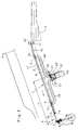
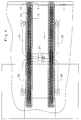
- a conveyor table 1 is arranged with two parallel conveyor belts 2 running around it between a stack 4 and alignment means 6 in the form of front marks 7 and / or side marks 8.
- the conveyor belts 2 are deflected by means of a deflecting roller 9 and a belt drive roller 11, these having a handy, e.g. B. has rubberized surface.
- the conveyor belts 2 have through openings 12 and a coated underside 13 with a small coefficient of friction.
- the exemplary embodiment described has two conveyor belts 2, as does sheet transport large format sheets required.
- the invention can also be used on conveyor tables 1 with only one conveyor belt 2 if correspondingly small sheet formats are to be processed.
- the openings 12 of the conveyor belts 2 are guided in the sheet transport direction (arrow) over the conveyor table 1 in such a way that they come into alignment with openings 14 on the upper side 16 of the conveyor table 1.
- the openings 12, 14 connect the upper side of the conveyor belts 2 to a suction chamber 17 of a single-chamber suction box 18 arranged under the conveying table 1.
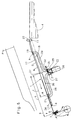
- Each suction box 18 has two suction connections 19, 21 spaced apart from one another, as seen in the sheet transport direction.
- a cross-sectional area A of the suction connection 19; 21 is the same size as a cross-sectional area B of the suction box 18.
- a distance A of the rear, i.e. H. seen in the sheet transport direction, the first suction connection 19 of upstream conveying means, in the form of the belt drive roller 11 in cooperation with an arranged indexing roller 22, is equal to the smallest preselectable scale length 1 (z. B. 200 mm).
- a distance b of the front, i.e. H. seen in the sheet transport direction - second suction port 21, of the front marks 7 corresponds at most to the length of the smallest format.
- the suction connections 19 and 21 are mounted in an outer side wall of the suction box 18 and connected to a housing 27 by means of air hoses 23 to 26 provided.
- a suction source in the form of a radial fan 28 is flanged to the housing 27.
- a swivel-mounted air guide flap 29 is arranged within the housing 27 and can be moved continuously from a first end position I to a second end position II.
- a remotely controllable adjusting element in the form of a working cylinder 31 is provided, which engages with the piston rod 32 on the air guide flap 29.
- the air guide flap 29 is brought into the first end position I, so that the total suction power of the radial fan 28 is connected to the rear suction port 19.
- a first sheet 33 is transported by the clock roller 22 and the belt drive roller 11 cooperating therewith in the sheet transport direction (arrow) until the leading edge of the sheet 33 covers the suction connection 19.
- a negative pressure is generated in the suction space 17 of the suction box 18 in the area covered by the sheet 33 in accordance with the diagram in FIG. 1. This has the effect that the first sheet 33 to be transported is already safely sucked onto the conveyor belt 12.
- the second and the further sheets 33 are now continuously transported in cycles by the transport elements 11, 22 until a conveying stream is formed from sheets 33 arranged under shingled, which completely covers the conveyor table 1 and thus the openings 12 of the conveyor belt 2.
- the position of the air guide flap 29 can assume both the first and the second end positions I; II. It is also possible for any other position to be set continuously between the end positions.
- the air guide flap 29 is brought into the second end position II.
- the source of suction air is switched off.
- Ambient air can now flow into the suction space 17 of the suction box 18 at the rear edge of the sheet 33. This causes the suction force on the underside of the sheet 33 to decrease and is only effective in a small area between the suction connection 21 and the beginning 34 of the suction box 18.
- the sheet 33 can be easily aligned laterally to the transport direction.
- the suction box 18 is provided with a variably adjustable suction chamber 17 in its front area.
- the bottom of the suction box 18 is designed as a pivotable flap 36, the pivot point being in the region of the front suction opening 21.
- a length L of the flap 36 is designed such that a distance c between the front marks 7 and the end 31 of the flap 36 is greater than the largest format length of the sheet 33 to be processed.
- Swiveling the flap 36 leads to an enlargement of the suction space in the front area and favors the ventilation of the suction box 18 during the transport of the last sheet to be processed.
Landscapes
- Delivering By Means Of Belts And Rollers (AREA)
- Feeding Of Articles By Means Other Than Belts Or Rollers (AREA)
- Separation, Sorting, Adjustment, Or Bending Of Sheets To Be Conveyed (AREA)
Applications Claiming Priority (2)
| Application Number | Priority Date | Filing Date | Title |
|---|---|---|---|
| DE19618870A DE19618870A1 (de) | 1996-05-10 | 1996-05-10 | Vorrichtung zum Fördern eines insbesondere geschuppten Stroms von Bogen zu einer bogenverarbeitenden Maschine |
| DE19618870 | 1996-05-10 |
Publications (3)
| Publication Number | Publication Date |
|---|---|
| EP0806389A2 true EP0806389A2 (fr) | 1997-11-12 |
| EP0806389A3 EP0806389A3 (fr) | 1998-12-09 |
| EP0806389B1 EP0806389B1 (fr) | 2002-07-24 |
Family
ID=7793951
Family Applications (1)
| Application Number | Title | Priority Date | Filing Date |
|---|---|---|---|
| EP97105895A Expired - Lifetime EP0806389B1 (fr) | 1996-05-10 | 1997-04-10 | Dispositif pour transporter un courant de feuilles se chevauchant |
Country Status (4)
| Country | Link |
|---|---|
| US (1) | US5951007A (fr) |
| EP (1) | EP0806389B1 (fr) |
| JP (1) | JPH1045309A (fr) |
| DE (2) | DE19618870A1 (fr) |
Cited By (1)
| Publication number | Priority date | Publication date | Assignee | Title |
|---|---|---|---|---|
| WO2024059112A3 (fr) * | 2022-09-14 | 2024-04-18 | Intpro, Llc | Détection de gauchissement dans un produit en carton ondulé en déplacement |
Families Citing this family (7)
| Publication number | Priority date | Publication date | Assignee | Title |
|---|---|---|---|---|
| US6575450B2 (en) | 2001-01-30 | 2003-06-10 | Lockheed Martin Corporation | Singulation mechanism |
| DE10129007C1 (de) * | 2001-06-15 | 2002-10-17 | Roland Man Druckmasch | Vorrichtung zum unterschuppten Zuführen von Bogen |
| DE10146919C1 (de) * | 2001-09-24 | 2003-05-15 | Koenig & Bauer Ag | Vorrichtung zur Ausrichtung von in einer Lage übereinander angeordneten Bogen |
| DE10229322A1 (de) * | 2002-06-29 | 2004-01-15 | Kolbus Gmbh & Co. Kg | Vorrichtung zum Vereinzeln eines Schuppenstroms von Druckprodukten in eine Folge beabstandeter Druckprodukte |
| DE102004015335A1 (de) | 2004-03-30 | 2005-10-20 | Koenig & Bauer Ag | Vorrichtung zum Zuführen eines geschuppten Bogenstromes |
| JP2006082923A (ja) * | 2004-09-15 | 2006-03-30 | Canon Inc | シート処理装置及びこれを備えた画像形成装置 |
| JP5111155B2 (ja) * | 2008-02-26 | 2012-12-26 | デュプロ精工株式会社 | 排紙装置 |
Family Cites Families (12)
| Publication number | Priority date | Publication date | Assignee | Title |
|---|---|---|---|---|
| DE713529C (de) * | 1938-11-05 | 1941-11-13 | Koenig Werk G M B H Maschf | Bogenfoerdervorrichtung, insbesondere an Bogenanlegern fuer Buchdruck- und aehnlicheMaschinen |
| DE1176672B (de) * | 1962-08-29 | 1964-08-27 | Johannisberg Ges Mit Beschraen | Rueckfrontbogenausleger an Druckmaschinen |
| DE1181240B (de) * | 1963-10-15 | 1964-11-12 | Mabeg Maschb G M B H Nachf Hen | Anlegetisch fuer Bogenanleger |
| DE2502668A1 (de) * | 1975-01-23 | 1976-07-29 | Mueller Forst C Kg | Verfahren und vorrichtung zum abheben und seitlichen abfoerdern von furnierblaettern oder dergl. von einer stapelflaeche |
| DE3331662A1 (de) * | 1983-09-02 | 1985-03-28 | M.A.N.- Roland Druckmaschinen AG, 6050 Offenbach | Verfahren und vorrichtung zum passgenauen bogentransport in eine druckmaschine |
| DE3903389A1 (de) * | 1989-02-04 | 1990-08-09 | Mabeg Maschinenbau Gmbh Nachf | Vorrichtung zum foerdern eines bogenstroms |
| DE4013302A1 (de) * | 1990-04-26 | 1991-10-31 | Koenig & Bauer Ag | Vorrichtung zum foerdern eines insbesondere geschuppten stroms von bogen |
| DE4108397C2 (de) * | 1991-03-15 | 1995-09-21 | Roland Man Druckmasch | Vorrichtung zur Bildung einer Folge von sich unterlappenden Gegenständen |
| DE4203511A1 (de) * | 1992-02-07 | 1993-08-12 | Roland Man Druckmasch | Vorrichtung zum foerdern eines geschuppten bogenstroms zu einer bogen verarbeitenden maschine |
| DE4314756C2 (de) * | 1993-05-05 | 1995-02-23 | Vits Maschinenbau Gmbh | Vorrichtung zum Schuppen und Ablegen von Bogen auf einen Stapel |
| DE4416289C2 (de) * | 1994-05-07 | 2003-06-05 | Heidelberger Druckmasch Ag | Vorrichtung zum Fördern eines geschuppten Bogenstromes |
| DE4416286C2 (de) * | 1994-05-07 | 1999-10-28 | Heidelberger Druckmasch Ag | Vorrichtung zur Anpassung des Unterdruckes in einem Saugbandzuführtisch eines Bogenanlegers |
-
1996
- 1996-05-10 DE DE19618870A patent/DE19618870A1/de not_active Withdrawn
-
1997
- 1997-04-10 DE DE59707763T patent/DE59707763D1/de not_active Expired - Fee Related
- 1997-04-10 EP EP97105895A patent/EP0806389B1/fr not_active Expired - Lifetime
- 1997-05-08 JP JP9117703A patent/JPH1045309A/ja not_active Ceased
- 1997-05-12 US US08/854,373 patent/US5951007A/en not_active Expired - Fee Related
Cited By (2)
| Publication number | Priority date | Publication date | Assignee | Title |
|---|---|---|---|---|
| WO2024059112A3 (fr) * | 2022-09-14 | 2024-04-18 | Intpro, Llc | Détection de gauchissement dans un produit en carton ondulé en déplacement |
| US12311632B2 (en) | 2022-09-14 | 2025-05-27 | Intpro, Llc | Warp detection in traveling corrugated product |
Also Published As
| Publication number | Publication date |
|---|---|
| DE59707763D1 (de) | 2002-08-29 |
| EP0806389B1 (fr) | 2002-07-24 |
| US5951007A (en) | 1999-09-14 |
| JPH1045309A (ja) | 1998-02-17 |
| EP0806389A3 (fr) | 1998-12-09 |
| DE19618870A1 (de) | 1997-11-13 |
Similar Documents
| Publication | Publication Date | Title |
|---|---|---|
| DE4442629C2 (de) | Saugbändertisch | |
| EP0155475B1 (fr) | Dispositif pour enlever des feuilles d'une pile et pour transporter les feuilles de la pile | |
| EP0075685B1 (fr) | Dispositif pour transporter un flux de feuilles de papier se chevauchant | |
| DE4433912A1 (de) | Stapelvorrichtung mit oberer Tafelführung | |
| DE10213705B4 (de) | Vorrichtung zum Fördern eines Bogenstroms von einem Bogenstapel zu einer bogenverarbeitenden Maschine | |
| DE1226605B (de) | Vorrichtung zum Vereinzeln und Abfoerdern von vertikal angeordneten und hochkant zu foerdernden Schriftstuecken | |
| EP1375399B1 (fr) | Dispositif pour séparer un courant de produits imprimés en formation imbriquée dans un courant de produits imprimés séparés les uns des autres | |
| EP1880960A2 (fr) | Dispositif d'alimentation d'un courant de feuilles se chevauchant | |
| EP0806389A2 (fr) | Dispositif pour transporter un courant de feuilles se chevauchant | |
| DE19817175A1 (de) | Vorrichtung zum Fördern eines insbesondere geschuppten Stroms von Bogen zu einer bogenverarbeitenden Maschine | |
| WO1999029599A1 (fr) | Dispositif pour transferer des produits en nappe sur un dispositif de transport | |
| DE2737558C2 (de) | Blattvereinzelungsgerät | |
| DE10131607A1 (de) | Ausleger einer flächige Bedruckstoffe verarbeitenden Maschine | |
| DE3941589A1 (de) | Vorrichtung zum vereinzeln und foerdern von gestapelten bogen | |
| DE19804120A1 (de) | Vorrichtung zum seitlichen Ausrichten von Bogen eines Bogenstromes | |
| DE3527277C2 (de) | Stapelvorrichtung zum Stapeln von Blättern unter Zuführung der Blätter an der Unterseite des Stapels | |
| EP1582490B1 (fr) | Dispositif d'alimentation d'un courant de feuilles se chevauchant | |
| DE4313150C2 (de) | Vorrichtung zum Vereinzeln von flachen Sendungen | |
| DE102018206097B4 (de) | Bogenleitvorrichtung | |
| DE102013224488A1 (de) | Vorrichtung zum Fördern eines geschuppten Bogenstroms | |
| DE4304832C2 (de) | Bogenausleger mit vertikaler Bogenstapelung für eine bogenbearbeitende Maschine, insbesondere eine Druckmaschine für den Offsetdruck | |
| DE102017208091B4 (de) | Bogenzuführvorrichtung für eine Druckmaschine | |
| EP2889245A2 (fr) | Dispositif de frein pneumatique et station d'imbrication associée, convoyeur de feuilles, et procédé de commande | |
| DD266076B1 (de) | Bogenleiteinrichtung in auslagen von druckmaschinen | |
| DE102005009223A1 (de) | Saugbändertisch |
Legal Events
| Date | Code | Title | Description |
|---|---|---|---|
| PUAI | Public reference made under article 153(3) epc to a published international application that has entered the european phase |
Free format text: ORIGINAL CODE: 0009012 |
|
| 17P | Request for examination filed |
Effective date: 19970410 |
|
| AK | Designated contracting states |
Kind code of ref document: A2 Designated state(s): CH DE FR GB IT LI |
|
| PUAL | Search report despatched |
Free format text: ORIGINAL CODE: 0009013 |
|
| AK | Designated contracting states |
Kind code of ref document: A3 Designated state(s): CH DE FR GB IT LI |
|
| 17Q | First examination report despatched |
Effective date: 20001110 |
|
| GRAG | Despatch of communication of intention to grant |
Free format text: ORIGINAL CODE: EPIDOS AGRA |
|
| GRAG | Despatch of communication of intention to grant |
Free format text: ORIGINAL CODE: EPIDOS AGRA |
|
| GRAH | Despatch of communication of intention to grant a patent |
Free format text: ORIGINAL CODE: EPIDOS IGRA |
|
| GRAH | Despatch of communication of intention to grant a patent |
Free format text: ORIGINAL CODE: EPIDOS IGRA |
|
| GRAA | (expected) grant |
Free format text: ORIGINAL CODE: 0009210 |
|
| AK | Designated contracting states |
Kind code of ref document: B1 Designated state(s): CH DE FR GB IT LI |
|
| PG25 | Lapsed in a contracting state [announced via postgrant information from national office to epo] |
Ref country code: IT Free format text: LAPSE BECAUSE OF FAILURE TO SUBMIT A TRANSLATION OF THE DESCRIPTION OR TO PAY THE FEE WITHIN THE PRESCRIBED TIME-LIMIT;WARNING: LAPSES OF ITALIAN PATENTS WITH EFFECTIVE DATE BEFORE 2007 MAY HAVE OCCURRED AT ANY TIME BEFORE 2007. THE CORRECT EFFECTIVE DATE MAY BE DIFFERENT FROM THE ONE RECORDED. Effective date: 20020724 Ref country code: GB Free format text: LAPSE BECAUSE OF FAILURE TO SUBMIT A TRANSLATION OF THE DESCRIPTION OR TO PAY THE FEE WITHIN THE PRESCRIBED TIME-LIMIT Effective date: 20020724 Ref country code: FR Free format text: LAPSE BECAUSE OF NON-PAYMENT OF DUE FEES Effective date: 20020724 |
|
| REG | Reference to a national code |
Ref country code: GB Ref legal event code: FG4D Free format text: NOT ENGLISH |
|
| REG | Reference to a national code |
Ref country code: CH Ref legal event code: EP |
|
| REF | Corresponds to: |
Ref document number: 59707763 Country of ref document: DE Date of ref document: 20020829 |
|
| GBV | Gb: ep patent (uk) treated as always having been void in accordance with gb section 77(7)/1977 [no translation filed] |
Effective date: 20020724 |
|
| EN | Fr: translation not filed | ||
| PG25 | Lapsed in a contracting state [announced via postgrant information from national office to epo] |
Ref country code: LI Free format text: LAPSE BECAUSE OF NON-PAYMENT OF DUE FEES Effective date: 20030430 Ref country code: CH Free format text: LAPSE BECAUSE OF NON-PAYMENT OF DUE FEES Effective date: 20030430 |
|
| PLBE | No opposition filed within time limit |
Free format text: ORIGINAL CODE: 0009261 |
|
| STAA | Information on the status of an ep patent application or granted ep patent |
Free format text: STATUS: NO OPPOSITION FILED WITHIN TIME LIMIT |
|
| 26N | No opposition filed |
Effective date: 20030425 |
|
| REG | Reference to a national code |
Ref country code: CH Ref legal event code: PL |
|
| PGFP | Annual fee paid to national office [announced via postgrant information from national office to epo] |
Ref country code: DE Payment date: 20070604 Year of fee payment: 11 |
|
| PG25 | Lapsed in a contracting state [announced via postgrant information from national office to epo] |
Ref country code: DE Free format text: LAPSE BECAUSE OF NON-PAYMENT OF DUE FEES Effective date: 20081101 |