EP0806389A2 - Device for forwarding a stream of overlapping sheets - Google Patents
Device for forwarding a stream of overlapping sheets Download PDFInfo
- Publication number
- EP0806389A2 EP0806389A2 EP97105895A EP97105895A EP0806389A2 EP 0806389 A2 EP0806389 A2 EP 0806389A2 EP 97105895 A EP97105895 A EP 97105895A EP 97105895 A EP97105895 A EP 97105895A EP 0806389 A2 EP0806389 A2 EP 0806389A2
- Authority
- EP
- European Patent Office
- Prior art keywords
- suction
- sheet
- suction box
- conveyor belt
- conveyor
- Prior art date
- Legal status (The legal status is an assumption and is not a legal conclusion. Google has not performed a legal analysis and makes no representation as to the accuracy of the status listed.)
- Granted
Links
- 239000003570 air Substances 0.000 description 13
- 238000010586 diagram Methods 0.000 description 2
- 239000012080 ambient air Substances 0.000 description 1
- 238000010276 construction Methods 0.000 description 1
- 238000011144 upstream manufacturing Methods 0.000 description 1
- 238000009423 ventilation Methods 0.000 description 1
Images


Classifications
-
- B—PERFORMING OPERATIONS; TRANSPORTING
- B65—CONVEYING; PACKING; STORING; HANDLING THIN OR FILAMENTARY MATERIAL
- B65H—HANDLING THIN OR FILAMENTARY MATERIAL, e.g. SHEETS, WEBS, CABLES
- B65H11/00—Feed tables
- B65H11/002—Feed tables incorporating transport belts
- B65H11/005—Suction belts
-
- B—PERFORMING OPERATIONS; TRANSPORTING
- B65—CONVEYING; PACKING; STORING; HANDLING THIN OR FILAMENTARY MATERIAL
- B65H—HANDLING THIN OR FILAMENTARY MATERIAL, e.g. SHEETS, WEBS, CABLES
- B65H2406/00—Means using fluid
- B65H2406/30—Suction means
- B65H2406/32—Suction belts
- B65H2406/322—Suction distributing means
- B65H2406/3223—Suction distributing means details of the openings in the belt, e.g. shape, distribution
Definitions
- the invention relates to a device for conveying an in particular scaled stream of sheets to a sheet-processing machine, with a conveyor table which is provided with at least one endless conveyor belt which can be driven all around it, with a suction box which is arranged under the conveyor table and is pressurized with suction and which has suction openings in the conveyor table is connected to the underside of the conveyor belt, which is provided with continuous suction holes.
- suction belt tables With such devices, so-called suction belt tables, the general problem is that the first and the last sheet must also be transported safely.
- the promotion of a shingled stream of sheets on the suction belt table can be divided into three phases.
- the first phase can be characterized in that when the machine starts up, the first sheet, which is pushed onto the suction belt by a separating device, should be sucked onto the perforated conveyor belt with as little slip as possible.
- the suction power is fundamentally reduced by the fact that only a certain area of the conveyor belt is covered by the first sheet and thus a great deal of incorrect air is sucked in, so that the suction effect is limited.
- this second phase namely the conveyance of the shingled arc stream, which corresponds approximately to the steady state or steady state of the system, constant operating conditions prevail, which is why this second phase can be classified as unproblematic.
- the third phase of the promotion of a shingled arc stream concerns the promotion of the last arc of the shingled arc stream.
- This bow is about his entire length is sucked onto the conveyor belt and is thus fixed much more strongly on the conveyor belt than the partially overlapping sheets of the scaled sheet stream.
- the overlapping of the individual sheets has the effect that the sheets are only in contact with the conveyor belt with a fraction of their surface area and are therefore subject to a lower suction effect. If the last sheet remains exposed to the negative pressure prevailing in the suction belt table during its transport, the front edge of the last sheet can be pressed in on the front marks on the one hand, or the lateral alignment can be insignificantly impeded on the other hand.
- DE 44 16 289 A1 a device for conveying an in particular scaled stream of sheets to a sheet-processing machine is known.
- the suction box provided in DE 44 16 289 is divided into individual suction chambers by means of profiles arranged therein, so that an effective vacuum can also be applied in the areas further away from the suction source, which vacuum is not influenced by the influence of leaks.
- the invention has for its object to provide a device for conveying an in particular scaled stream of sheets, in which the first and the last sheet to be processed is safely transported.
- the advantage of the invention is, in particular, that a small space-saving size can be achieved in the single-chamber suction box according to the invention. Due to this simple, small-volume construction of a suction box assigned to each conveyor belt, suction sources (e.g. blowers) with low power can be used.
- suction sources e.g. blowers
- a particular advantage also lies in the fact that a complicated subdivision of the suction box into several chambers arranged one behind the other in the sheet transport direction is not necessary.
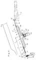
- a conveyor table 1 is arranged with two parallel conveyor belts 2 running around it between a stack 4 and alignment means 6 in the form of front marks 7 and / or side marks 8.
- the conveyor belts 2 are deflected by means of a deflecting roller 9 and a belt drive roller 11, these having a handy, e.g. B. has rubberized surface.
- the conveyor belts 2 have through openings 12 and a coated underside 13 with a small coefficient of friction.
- the exemplary embodiment described has two conveyor belts 2, as does sheet transport large format sheets required.
- the invention can also be used on conveyor tables 1 with only one conveyor belt 2 if correspondingly small sheet formats are to be processed.
- the openings 12 of the conveyor belts 2 are guided in the sheet transport direction (arrow) over the conveyor table 1 in such a way that they come into alignment with openings 14 on the upper side 16 of the conveyor table 1.
- the openings 12, 14 connect the upper side of the conveyor belts 2 to a suction chamber 17 of a single-chamber suction box 18 arranged under the conveying table 1.
- Each suction box 18 has two suction connections 19, 21 spaced apart from one another, as seen in the sheet transport direction.
- a cross-sectional area A of the suction connection 19; 21 is the same size as a cross-sectional area B of the suction box 18.
- a distance A of the rear, i.e. H. seen in the sheet transport direction, the first suction connection 19 of upstream conveying means, in the form of the belt drive roller 11 in cooperation with an arranged indexing roller 22, is equal to the smallest preselectable scale length 1 (z. B. 200 mm).
- a distance b of the front, i.e. H. seen in the sheet transport direction - second suction port 21, of the front marks 7 corresponds at most to the length of the smallest format.
- the suction connections 19 and 21 are mounted in an outer side wall of the suction box 18 and connected to a housing 27 by means of air hoses 23 to 26 provided.
- a suction source in the form of a radial fan 28 is flanged to the housing 27.
- a swivel-mounted air guide flap 29 is arranged within the housing 27 and can be moved continuously from a first end position I to a second end position II.
- a remotely controllable adjusting element in the form of a working cylinder 31 is provided, which engages with the piston rod 32 on the air guide flap 29.
- the air guide flap 29 is brought into the first end position I, so that the total suction power of the radial fan 28 is connected to the rear suction port 19.
- a first sheet 33 is transported by the clock roller 22 and the belt drive roller 11 cooperating therewith in the sheet transport direction (arrow) until the leading edge of the sheet 33 covers the suction connection 19.
- a negative pressure is generated in the suction space 17 of the suction box 18 in the area covered by the sheet 33 in accordance with the diagram in FIG. 1. This has the effect that the first sheet 33 to be transported is already safely sucked onto the conveyor belt 12.
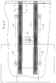
- the second and the further sheets 33 are now continuously transported in cycles by the transport elements 11, 22 until a conveying stream is formed from sheets 33 arranged under shingled, which completely covers the conveyor table 1 and thus the openings 12 of the conveyor belt 2.
- the position of the air guide flap 29 can assume both the first and the second end positions I; II. It is also possible for any other position to be set continuously between the end positions.
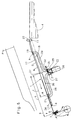
- the air guide flap 29 is brought into the second end position II.
- the source of suction air is switched off.
- Ambient air can now flow into the suction space 17 of the suction box 18 at the rear edge of the sheet 33. This causes the suction force on the underside of the sheet 33 to decrease and is only effective in a small area between the suction connection 21 and the beginning 34 of the suction box 18.
- the sheet 33 can be easily aligned laterally to the transport direction.
- the suction box 18 is provided with a variably adjustable suction chamber 17 in its front area.
- the bottom of the suction box 18 is designed as a pivotable flap 36, the pivot point being in the region of the front suction opening 21.
- a length L of the flap 36 is designed such that a distance c between the front marks 7 and the end 31 of the flap 36 is greater than the largest format length of the sheet 33 to be processed.
- Swiveling the flap 36 leads to an enlargement of the suction space in the front area and favors the ventilation of the suction box 18 during the transport of the last sheet to be processed.
Abstract
Description
Die Erfindung betrifft eine Vorrichtung zum Fördern eines insbesondere geschuppten Stroms von Bogen zu einer bogenverarbeitenden Maschine, mit einem Fördertisch, der mit mindestens einem endlosen, ihn umlaufend antreibbaren Transportband versehen ist, mit einem unter dem Fördertisch angeordneten, unterdruckbeaufschlagten Saugkasten, der über Saugöffnungen im Fördertisch mit der Unterseite des Transportbandes verbunden ist, welches mit durchgehenden Sauglöchern versehen ist.The invention relates to a device for conveying an in particular scaled stream of sheets to a sheet-processing machine, with a conveyor table which is provided with at least one endless conveyor belt which can be driven all around it, with a suction box which is arranged under the conveyor table and is pressurized with suction and which has suction openings in the conveyor table is connected to the underside of the conveyor belt, which is provided with continuous suction holes.
Bei derartigen Vorrichtungen, sogenannten Saugbandertischen, liegt das allgemeine Problem darin, daß auch der erste und der letzte Bogen sicher transportiert werden muß. Die Förderung eines geschuppten Bogenstromes auf dem Saugbändertisch läßt sich hierbei in drei Phasen unterteilen.With such devices, so-called suction belt tables, the general problem is that the first and the last sheet must also be transported safely. The promotion of a shingled stream of sheets on the suction belt table can be divided into three phases.
Die erste Phase läßt sich dadurch charakterisieren, daß bei Maschinenanlauf der erste Bogen, der von einer Vereinzelungsvorrichtung auf das Saugband geschoben wird, möglichst schlupfarm auf das gelochte Transportband angesaugt werden soll. In dieser Phase des Maschinenbetriebes ist die Saugkraft jedoch grundsätzlich dadurch gemindert, daß nur ein gewisser Bereich des Transportbandes durch den ersten Bogen abgedeckt wird und somit sehr viel Fehlluft angesaugt wird, so daß die Saugwirkung begrenzt ist.The first phase can be characterized in that when the machine starts up, the first sheet, which is pushed onto the suction belt by a separating device, should be sucked onto the perforated conveyor belt with as little slip as possible. In this phase of the machine operation, however, the suction power is fundamentally reduced by the fact that only a certain area of the conveyor belt is covered by the first sheet and thus a great deal of incorrect air is sucked in, so that the suction effect is limited.
In der zweiten Phase, nämlich der Förderung des geschuppten Bogenstromes, die etwa dem stationären oder eingeschwungenen Zustand des Systems entspricht, herrschen konstante Betriebsbedingungen, weswegen diese zweite Phase als unproblematisch einzustufen ist.In the second phase, namely the conveyance of the shingled arc stream, which corresponds approximately to the steady state or steady state of the system, constant operating conditions prevail, which is why this second phase can be classified as unproblematic.
Die dritte Phase der Förderung eines geschuppten Bogenstromes betrifft die Förderung des letzten Bogens des geschuppten Bogenstromes. Dieser Bogen wird über seine gesamte Länge auf das Transportband gesaugt und ist somit wesentlich stärker auf dem Transportband fixiert, als die sich teilweise überlappenden Bogen des geschuppten Bogenstromes. Bei diesem bewirkt das Überlappen der einzelnen Bögen, daß die Bögen nur mit einem Bruchteil ihrer Fläche mit dem Transportband in Kontakt stehen und demzufolge einer geringeren Ansaugwirkung unterworfen sind. Bleibt der letzte Bogen bei seinem Transport gegen die Vordermarken, dem im Saugbändertisch herrschenden Unterdruck ausgesetzt, so kann einerseits die Vorderkante des letzten Bogens an den Vordermarken eingedrückt oder andererseits die seitliche Ausrichtung nicht unerheblich behindert werden.The third phase of the promotion of a shingled arc stream concerns the promotion of the last arc of the shingled arc stream. This bow is about his entire length is sucked onto the conveyor belt and is thus fixed much more strongly on the conveyor belt than the partially overlapping sheets of the scaled sheet stream. In this case, the overlapping of the individual sheets has the effect that the sheets are only in contact with the conveyor belt with a fraction of their surface area and are therefore subject to a lower suction effect. If the last sheet remains exposed to the negative pressure prevailing in the suction belt table during its transport, the front edge of the last sheet can be pressed in on the front marks on the one hand, or the lateral alignment can be insignificantly impeded on the other hand.
Durch die DE 44 16 289 A1 ist eine Vorrichtung zum Fördern eines insbesondere geschuppten Stroms von Bogen zu einer bogenverarbeitenden Maschine bekannt. Der bei der DE 44 16 289 vorgesehene Saugkasten ist mittels darin angeordneter Profile in einzelne Saugkammern aufgeteilt, damit auch in den weiter von der Saugquelle entfernt angeordneten Bereichen ein wirksames Vakuum anstehen kann, welches nicht durch den Einfluß von Leckagen beeinflußt wird.From DE 44 16 289 A1, a device for conveying an in particular scaled stream of sheets to a sheet-processing machine is known. The suction box provided in DE 44 16 289 is divided into individual suction chambers by means of profiles arranged therein, so that an effective vacuum can also be applied in the areas further away from the suction source, which vacuum is not influenced by the influence of leaks.
Der Erfindung liegt die Aufgabe zugrunde, eine Vorrichtung zum Fördern eines insbesondere geschuppten Stroms von Bogen zu schaffen, bei dem auch der erste und der letzte zu verarbeitende Bogen sicher transportiert wird.The invention has for its object to provide a device for conveying an in particular scaled stream of sheets, in which the first and the last sheet to be processed is safely transported.
Die Aufgabe wird erfindungsgemäß durch die kennzeichnenden Merkmale des Anspruchs 1 gelöst.The object is achieved by the characterizing features of
Der Vorteil der Erfindung liegt insbesondere darin, daß beim erfindungsgemäßen Einkammer-Saugkasten eine geringe platzsparende Baugröße verwirklicht werden kann. Durch diesen einfachen, kleinvolumigen Aufbau eines jedem Transportband zugeordneten Saugkastens, können Saugquellen (z. B. Gebläse) mit kleiner Leistung eingesetzt werden.The advantage of the invention is, in particular, that a small space-saving size can be achieved in the single-chamber suction box according to the invention. Due to this simple, small-volume construction of a suction box assigned to each conveyor belt, suction sources (e.g. blowers) with low power can be used.
Ein besonderer Vorteil liegt auch darin, daß eine aufwendige Unterteilung des Saugkastens in mehrere in Bogentransportrichtung gesehen, hintereinander angeordnete Kammern nicht notwendig ist.A particular advantage also lies in the fact that a complicated subdivision of the suction box into several chambers arranged one behind the other in the sheet transport direction is not necessary.
Ein Ausführungsbeispiel der Erfindung ist in den Zeichnungen dargestellt und wird im folgenden beschrieben.
Es zeigen:
- Fig. 1
- eine schematische Seitenansicht des erfindungsgemäßen Saugbänder-Fördertisches im Schnitt beim Einlauf des ersten zu verarbeitenden Bogens,
- Fig. 2
- eine schematische Seitenansicht des erfindungsgemäßen Saugband-Fördertisches im Schnitt bei voll abgedecktem Fördertisch,
- Fig. 3
- eine schematische Seitenansicht des erfindungsgemäßen Saugbänder-Fördertisches im Schnitt bei Anlage des letzten zu verarbeitenden Bogens an den Vordermarken,
- Fig. 4
- eine schematische Draufsicht auf den Saugbänder-Fördertisch,
- Fig. 5
- ein weiteres Ausführungsbeispiel.
Show it:
- Fig. 1
- FIG. 2 shows a schematic side view of the suction belt conveyor table according to the invention in section at the entry of the first sheet to be processed,
- Fig. 2
- 2 shows a schematic side view of the suction belt conveyor table according to the invention in section with the conveyor table fully covered,
- Fig. 3
- 2 shows a schematic side view of the suction belt conveyor table according to the invention in section when the last sheet to be processed is placed against the front marks,
- Fig. 4
- a schematic plan view of the suction belt conveyor table,
- Fig. 5
- another embodiment.
Ein Fördertisch 1 ist mit zwei ihn umlaufenden parallel angeordneten Transportbändern 2 zwischen einem Stapel 4 und Ausrichtmitteln 6 in Form von Vordermarken 7 und/oder Seitenmarken 8 angeordnet.A conveyor table 1 is arranged with two
Die Transportbänder 2 werden mittels einer Umlenkwalze 9 und einer Bänderantriebswalze 11 umgelenkt, wobei diese eine griffige, z. B. gummierte Oberfläche aufweist. Die Transportbänder 2 weisen durchgehende Öffnungen 12 und eine beschichtete Unterseite 13 mit kleinem Reibungskoeffizienten auf. Das beschriebene Ausführungsbeispiel weist zwei Transportbänder 2 auf, wie es der Bogentransport großformatiger Bögen erfordert. Selbstverständlich ist die Erfindung auch an Fördertischen 1 mit nur einem Transportband 2 einsetzbar, wenn entsprechend kleine Bogenformate zu verarbeiten sind.The
Die Öffnungen 12 der Transportbänder 2 werden in Bogentransportrichtung (Pfeil ) derart über den Fördertisch 1 geführt, daß diese in Deckung mit Öffnungen 14 an der Oberseite 16 des Fördertisches 1 gelangen. Die Öffnungen 12,14 verbinden die Oberseite der Transportbänder 2 mit jeweils einem unter dem Fördertisch 1 angeordneten Saugraum 17 eines Ein-Kammer-Saugkastens 18. Jeder Saugkasten 18 weist zwei - in Bogentransportrichtung gesehen - voneinander beabstandete Sauganschlüsse 19,21 auf. Eine Querschnittsfläche A des Sauganschlußes 19;21 ist genauso groß wie eine Querschnittsfläche B des Saugkastens 18.The
Ein Abstand A des hinteren, d. h. in Bogentransportrichtung gesehen ersten Sauganschlusses 19 von vorgeordneten Fördermitteln, in Form der Bänderantriebswalze 11 in Zusammenwirken mit einer angeordneten Taktwalze 22, ist gleich der kleinsten vorwählbaren Schuppenlänge 1 (z. B. 200 mm). Ein Abstand b des vorderen, d. h. in Bogentransportrichtung gesehen - zweiten Sauganschlusses 21, von den Vordermarken 7 entspricht höchstens der Länge des kleinsten Formates. Die Sauganschlüsse 19 und 21 sind in einer äußeren Seitenwand des Saugkastens 18 angebracht und mittels vorgesehener Luftschläuche 23 bis 26 mit einem Gehäuse 27 verbunden. An das Gehäuse 27 ist eine Saugquelle in Form eines Radialgebläses 28 angeflanscht. Innerhalb des Gehäuses 27 ist eine schwenkbar angeordnete Luft-Leit-Klappe 29 angeordnet, welches stufenlos von einer ersten Endstellung I in eine zweite Endstellung II verbringbar ist.A distance A of the rear, i.e. H. seen in the sheet transport direction, the
Zu diesem Zweck ist ein fernbedienbares Stellelement in Form eines Arbeitszylinders 31 vorgesehen, welcher mit seiner Kolbenstange 32 an der Luft-Leit-Klappe 29 angreift.For this purpose, a remotely controllable adjusting element in the form of a working
Zunächst wird die Luft-Leit-Klappe 29 in die erste Endstellung I verbracht, so daß die gesamte Saugleistung des Radialgebläses 28 auf den hinteren Sauganschluß 19 geschaltet ist. Daraufhin wird ein erster Bogen 33 von der Taktwalze 22 und der mit dieser zusammenwirkenden Bandantriebswalze 11 soweit in Bogentransportrichtung (Pfeil) transportiert, bis die vorauslaufende Kante des Bogens 33 den Sauganschluß 19 überdeckt. Hierdurch wird in dem Bereich der von dem Bogen 33 abgedeckt ist, ein Unterdruck im Saugraum 17 des Saugkastens 18 entsprechend dem Diagramm in Fig. 1 erzeugt. Dieser bewirkt, daß der erste zu transportierende Bogen 33 bereits sicher auf das Transportband 12 angesaugt wird.First, the
Der zweite und die weiteren Bögen 33 werden nunmehr von den Transportelementen 11,22 fortlaufend taktweise weitertransportiert, bis ein Förderstrom aus unterschuppt angeordneten Bögen 33 gebildet ist, der den Fördertisch 1 und damit die Öffnungen 12 des Transportbandes 2 vollständig abdeckt. Hierbei ergibt sich ein konstanter Unterdruck im gesamten Saugraum 17 des Saugkastens 18, wie er in dem Diagramm der Figur 2 dargestellt ist. Die Stellung der Luft-Leit-Klappe 29 kann hierbei sowohl die erste, als auch die zweite Endstellung I;II einnehmen. Es ist auch möglich, daß stufenlos eine zwischen den Endstellungen beliebige andere Stellung eingestellt wird.The second and the further sheets 33 are now continuously transported in cycles by the
Vor dem Transport des letzten zu verarbeitenden Bogens 23 wird die Luft-Leit-Klappe 29 in die zweite Endstellung II verbracht. Beim Anschlag des letzten Bogens 33 an den Vordermarken 7, wird die Saugluftquelle abgestellt. Nunmehr kann Umgebungsluft an der Hinterkante des Bogens 33 in den Saugraum 17 des Saugkastens 18 einströmen. Diese bewirkt, daß die Saugkraft auf die Unterseite des Bogens 33 nachläßt und nur noch in einem kleinen Bereich zwischen Sauganschluß 21 und Anfang 34 des Saugkastens 18 wirksam ist. Durch diese Maßnahme läßt sich der Bogen 33 leicht seitlich zur Transportrichtung ausrichten.Before the
Bei einem zweiten Ausführungsbeispiel (Fig. 5) ist es vorgesehen, den Saugkasten 18 in seinem vorderen Bereich mit einem variabel verstellbaren Saugraum 17 zu versehen.In a second embodiment (FIG. 5) it is provided that the
Hierbei ist der Boden des Saugkastens 18 als schwenkbare Klappe 36 ausgebildet, wobei der Schwenkpunkt im Bereich der vorderen Saugöffnung 21 liegt. Eine Länge L der Klappe 36 ist so ausgelegt, daß ein Abstand c zwischen den Vordermarken 7 und dem Ende 31 der Klappe 36 größer ist, als die größte zu verarbeitende Formatlänge des Bogens 33.Here, the bottom of the
Ein Abschwenken der Klappe 36 führt zu einer Saugraumvergrößerung im vorderen Bereich und begünstigt die Belüftung des Saugkastens 18 beim Transport des letzten zu verarbeitenden Bogens.Swiveling the
- 11
- FördertischPromotion table
- 22nd
- TransportbandConveyor belt
- 33rd
- 44th
- BogenstapelSheet stack
- 55
- 66
- AusrichtmittelAlignment means
- 77
- VordermarkeFront mark
- 88th
- SeitenmarkeSide mark
- 99
- UmlenkwalzeDeflection roller
- 1010th
- 1111
- BandantriebswalzeBelt drive roller
- 1212th
- Öffnungen (2)Openings (2)
- 1313
- Unterseite (2)Bottom (2)
- 1414
- Öffnungen (1,16)Openings (1.16)
- 1515
- 1616
- Oberseite (1)Top (1)
- 1717th
- Saugraum (18)Suction chamber (18)
- 1818th
- SaugkastenSuction box
- 1919th
- SauganschlußSuction connection
- 2020th
- 2121
- SauganschlußSuction connection
- 2222
- TaktwalzeClock roller
- 2323
- LuftschlauchAir hose
- 2424th
- LuftschlauchAir hose
- 2525th
- LuftschlauchAir hose
- 2626
- LuftschlauchAir hose
- 2727
- Gehäusecasing
- 2828
- RadialgebläseRadial fan
- 2929
- Luft-Leit-KlappeAir guide flap
- 3030th
- 3131
- ArbeitszylinderWorking cylinder
- 3232
- KolbenstangePiston rod
- 3333
- Bogenbow
- 3434
- Anfang (18)Early (18)
- 3535
- 3636
- Klappeflap
- 3737
- Ende (36)End (36)
- AA
- Querschnittsfläche (19;21)Cross-sectional area (19; 21)
- BB
- Querschnittsfläche (18)Cross-sectional area (18)
- aa
- Abstand (19-22)Distance (19-22)
- bb
- Abstand (21-7)Distance (21-7)
- cc
- Abstand (7-37)Distance (7-37)
- ll
- SchuppenlängeScale length
- LL
- Länge (36)Length (36)
- II.
- erste Endstellung (29)first end position (29)
- IIII
- zweite Endstellung (29)second end position (29)
Claims (9)
dadurch gekennzeichnet,
daß jedem Transportband (2) ein einziger aus einer einzigen Saugkammer (17) bestehender Saugkasten (18) zugeordnet ist und daR der Saugkasten (18) - in Bogentransportrichtung gesehen - mindestens zwei voneinander beabstandete Sauganschlüsse (19,21) aufweist.Device for conveying a stream, in particular flaked, from a sheet to a sheet-processing machine, with a conveyor table which is provided with at least one endless conveyor belt which can be driven around it, with a suction box which is arranged under the conveyor table and is under pressure and which is connected to the underside of the conveyor table via suction openings in the conveyor table Conveyor belt is connected, which is provided with continuous suction holes,
characterized,
that each conveyor belt (2) is assigned a single suction box (18) consisting of a single suction chamber (17) and that the suction box (18) - as seen in the sheet transport direction - has at least two suction connections (19, 21) spaced from one another.
dadurch gekennzeichnet,
daß der vordere, der der bogenverarbeitenden Maschine zugewandte Sauganschluß (21) in einem Abstand (b) von vorgesehenen Ausrichtmitteln (7,8) angeordnet ist, der höchstens der Formatlänge des kleinsten zu verarbeitenden Bogens entspricht.Device according to one of the preceding claims,
characterized,
that the front suction port (21) facing the sheet-processing machine is arranged at a distance (b) from the provided alignment means (7, 8) which corresponds at most to the format length of the smallest sheet to be processed.
dadurch gekennzeichnet,
daß der in einem hinteren der bogenverarbeitenden Maschine abgewandten Bereich angeordnete Saugstutzen (19) in einem Abstand (a) zum Bogenstapel (4) angeordnet ist, der der kleinsten zu verarbeitenden Schuppenlänge (l) entspricht.Device according to one of the preceding claims,
characterized,
that the suction nozzle (19) arranged in a rear area facing away from the sheet-processing machine is arranged at a distance (a) from the sheet stack (4) which corresponds to the smallest scale length (l) to be processed.
dadurch gekennzeichnet,
daß die Sauganschlüsse (19,21) mit Saugluft beaufschlagbar sind und daß jeweils einer der Sauganschlüsse (19,21) abschaltbar ist.Device according to one of the preceding claims,
characterized,
that the suction connections (19, 21) can be acted upon by suction air and that in each case one of the suction connections (19, 21) can be switched off.
dadurch gekennzeichnet,
daß eine schaltbare Luft-Leit-Klappe (29) vorgesehen ist.Device according to one of the preceding claims,
characterized,
that a switchable air guide flap (29) is provided.
dadurch gekennzeichnet,
daß der Saugkasten (18) einen Querschnitt (B) aufweist, der den Querschnitt (A) eines Sauganschlusses (19;21) entspricht.Device according to one of the preceding claims,
characterized,
that the suction box (18) has a cross section (B) which corresponds to the cross section (A) of a suction connection (19; 21).
dadurch gekennzeichnet,
daß ein vorderer Bereich des Saugkastens (18) einen in Querschnitt und Volumen vergrößerten Saugraum aufweist.Device according to one of the preceding claims 1 to 6,
characterized,
that a front area of the suction box (18) has an enlarged suction chamber in cross section and volume.
dadurch gekennzeichnet,
daß zur Vergrößerung des Saugraumes eine schwenkbar angeordnete Klappe (36) vorgesehen ist.Device according to claim 7,
characterized,
that a pivotable flap (36) is provided to enlarge the suction space.
dadurch gekennzeichnet,
daß die Saugraumvergrößerung in einem Abstand (c) von den Vordermarken (7) angeordnet ist, der größer als die zu verarbeitende Formatlänge ist.Device according to claim 8,
characterized,
that the suction chamber enlargement is arranged at a distance (c) from the front marks (7) which is greater than the format length to be processed.
Applications Claiming Priority (2)
| Application Number | Priority Date | Filing Date | Title |
|---|---|---|---|
| DE19618870 | 1996-05-10 | ||
| DE19618870A DE19618870A1 (en) | 1996-05-10 | 1996-05-10 | Device for conveying an in particular flaky stream of sheets to a sheet processing machine |
Publications (3)
| Publication Number | Publication Date |
|---|---|
| EP0806389A2 true EP0806389A2 (en) | 1997-11-12 |
| EP0806389A3 EP0806389A3 (en) | 1998-12-09 |
| EP0806389B1 EP0806389B1 (en) | 2002-07-24 |
Family
ID=7793951
Family Applications (1)
| Application Number | Title | Priority Date | Filing Date |
|---|---|---|---|
| EP97105895A Expired - Lifetime EP0806389B1 (en) | 1996-05-10 | 1997-04-10 | Device for forwarding a stream of overlapping sheets |
Country Status (4)
| Country | Link |
|---|---|
| US (1) | US5951007A (en) |
| EP (1) | EP0806389B1 (en) |
| JP (1) | JPH1045309A (en) |
| DE (2) | DE19618870A1 (en) |
Families Citing this family (7)
| Publication number | Priority date | Publication date | Assignee | Title |
|---|---|---|---|---|
| US6575450B2 (en) | 2001-01-30 | 2003-06-10 | Lockheed Martin Corporation | Singulation mechanism |
| DE10129007C1 (en) * | 2001-06-15 | 2002-10-17 | Roland Man Druckmasch | Feed system for paper sheets, to a sheet-fed printing press, has controlled deflection rollers at the suction belt to act on the sheets moving over the kinked transfer point between the feed plane and the belt |
| DE10146919C1 (en) * | 2001-09-24 | 2003-05-15 | Koenig & Bauer Ag | Device for aligning sheets arranged one above the other in a layer |
| DE10229322A1 (en) * | 2002-06-29 | 2004-01-15 | Kolbus Gmbh & Co. Kg | Device for separating a shingled stream of printed products into a sequence of spaced-apart printed products |
| DE102004015335A1 (en) * | 2004-03-30 | 2005-10-20 | Koenig & Bauer Ag | Apparatus for feeding a scaly arc stream |
| JP2006082923A (en) * | 2004-09-15 | 2006-03-30 | Canon Inc | Sheet treatment device and image formation device provided with this |
| JP5111155B2 (en) * | 2008-02-26 | 2012-12-26 | デュプロ精工株式会社 | Paper discharge device |
Citations (5)
| Publication number | Priority date | Publication date | Assignee | Title |
|---|---|---|---|---|
| DE1181240B (en) * | 1963-10-15 | 1964-11-12 | Mabeg Maschb G M B H Nachf Hen | Feed table for sheet feeder |
| GB1006394A (en) * | 1962-08-29 | 1965-09-29 | Johannisberg Gmbh Maschf | Improvements relating to a method of and apparatus for turning and depositing printed sheets in printing machines |
| US4651984A (en) * | 1983-09-02 | 1987-03-24 | M.A.N.-Roland Druckmaschinen Aktiengesellschaft | Method of and apparatus for accurate-register sheet transport in a printing machine |
| US5133543A (en) * | 1990-04-26 | 1992-07-28 | Koenig & Bauer Aktiengesellschaft | Sheet conveying apparatus |
| DE4416289A1 (en) * | 1994-05-07 | 1995-11-09 | Heidelberger Druckmasch Ag | Device for conveying a shingled stream of sheets |
Family Cites Families (7)
| Publication number | Priority date | Publication date | Assignee | Title |
|---|---|---|---|---|
| DE713529C (en) * | 1938-11-05 | 1941-11-13 | Koenig Werk G M B H Maschf | Sheet conveying device, especially on sheet feeders for letterpress and similar machines |
| DE2502668A1 (en) * | 1975-01-23 | 1976-07-29 | Mueller Forst C Kg | Lifting and removing veneer sheets from stack - sheets held by suction on bottom surface of conveyor and transferred |
| DE3903389A1 (en) * | 1989-02-04 | 1990-08-09 | Mabeg Maschinenbau Gmbh Nachf | Device for conveying a stream of sheets |
| DE4108397C2 (en) * | 1991-03-15 | 1995-09-21 | Roland Man Druckmasch | Device for forming a sequence of objects that overlap |
| DE4203511A1 (en) * | 1992-02-07 | 1993-08-12 | Roland Man Druckmasch | DEVICE FOR PROMOTING A SCALED FLOW CURRENT TO A BOW PROCESSING MACHINE |
| DE4314756C2 (en) * | 1993-05-05 | 1995-02-23 | Vits Maschinenbau Gmbh | Device for shedding and depositing sheets on a stack |
| DE4416286C2 (en) * | 1994-05-07 | 1999-10-28 | Heidelberger Druckmasch Ag | Device for adjusting the negative pressure in a suction belt feed table of a sheet feeder |
-
1996
- 1996-05-10 DE DE19618870A patent/DE19618870A1/en not_active Withdrawn
-
1997
- 1997-04-10 DE DE59707763T patent/DE59707763D1/en not_active Expired - Fee Related
- 1997-04-10 EP EP97105895A patent/EP0806389B1/en not_active Expired - Lifetime
- 1997-05-08 JP JP9117703A patent/JPH1045309A/en not_active Ceased
- 1997-05-12 US US08/854,373 patent/US5951007A/en not_active Expired - Fee Related
Patent Citations (5)
| Publication number | Priority date | Publication date | Assignee | Title |
|---|---|---|---|---|
| GB1006394A (en) * | 1962-08-29 | 1965-09-29 | Johannisberg Gmbh Maschf | Improvements relating to a method of and apparatus for turning and depositing printed sheets in printing machines |
| DE1181240B (en) * | 1963-10-15 | 1964-11-12 | Mabeg Maschb G M B H Nachf Hen | Feed table for sheet feeder |
| US4651984A (en) * | 1983-09-02 | 1987-03-24 | M.A.N.-Roland Druckmaschinen Aktiengesellschaft | Method of and apparatus for accurate-register sheet transport in a printing machine |
| US5133543A (en) * | 1990-04-26 | 1992-07-28 | Koenig & Bauer Aktiengesellschaft | Sheet conveying apparatus |
| DE4416289A1 (en) * | 1994-05-07 | 1995-11-09 | Heidelberger Druckmasch Ag | Device for conveying a shingled stream of sheets |
Also Published As
| Publication number | Publication date |
|---|---|
| US5951007A (en) | 1999-09-14 |
| JPH1045309A (en) | 1998-02-17 |
| EP0806389B1 (en) | 2002-07-24 |
| DE19618870A1 (en) | 1997-11-13 |
| EP0806389A3 (en) | 1998-12-09 |
| DE59707763D1 (en) | 2002-08-29 |
Similar Documents
| Publication | Publication Date | Title |
|---|---|---|
| EP0075685B1 (en) | Device for conveying a progression of overlapping sheets of paper | |
| EP0408893B1 (en) | Sheet depositing device for revolving transverse cutter | |
| EP1880960B1 (en) | Device for feeding a stream of overlapping sheets | |
| DE1226605B (en) | Device for the separation and removal of vertically arranged documents to be conveyed on edge | |
| DE10213705B4 (en) | Apparatus for conveying a sheet flow from a sheet stack to a sheet processing machine | |
| EP0155475A1 (en) | Apparatus for removing sheets from a pile and for transporting the sheets from the pile | |
| EP1375399B1 (en) | Apparatus for separating a stream of overlapping printed products into a stream of spaced apart printed products | |
| DE19817175A1 (en) | Device to deliver especially ragged flow of paper sheets to processing machine | |
| EP0806389A2 (en) | Device for forwarding a stream of overlapping sheets | |
| EP1037829A1 (en) | Device for transferring two-dimensional products onto a transportation device | |
| EP1582490B1 (en) | Device for feeding a stream of overlapping sheets | |
| DD278566A1 (en) | DEVICE FOR ASSEMBLING AND SUPPORTING STACKED BOWS | |
| DE2737558C2 (en) | Sheet separator | |
| DE19616714A1 (en) | Sheet paper conveyor | |
| DE19606833A1 (en) | Sheet pile feeder | |
| DE19804120A1 (en) | Sidewards alignment device for sheets of sheet stream in sheet processing machine | |
| DE3527277C2 (en) | Stacking device for stacking sheets while feeding the sheets at the bottom of the stack | |
| EP1698578A2 (en) | Table with suction belts | |
| DE4313150A1 (en) | Separation method and device | |
| DE2707040A1 (en) | Offset printing press sheet feed - has auxiliary sucker fitted opposite sensor element at sheet stack rear edge (CS 30.6.77) | |
| DE4423653A1 (en) | Sheet handling device using suction | |
| EP1698577B1 (en) | Table with suction belts | |
| DE4304832C2 (en) | Sheet delivery with vertical sheet stacking for a sheet processing machine, in particular a printing machine for offset printing | |
| DE102019126657B4 (en) | Separating device and method for separating thin sheet units from a stack of sheets by means of a separating device | |
| EP2889245A2 (en) | Suction braking device and corresponding overlapping station, sheets conveyor, and control method |
Legal Events
| Date | Code | Title | Description |
|---|---|---|---|
| PUAI | Public reference made under article 153(3) epc to a published international application that has entered the european phase |
Free format text: ORIGINAL CODE: 0009012 |
|
| 17P | Request for examination filed |
Effective date: 19970410 |
|
| AK | Designated contracting states |
Kind code of ref document: A2 Designated state(s): CH DE FR GB IT LI |
|
| PUAL | Search report despatched |
Free format text: ORIGINAL CODE: 0009013 |
|
| AK | Designated contracting states |
Kind code of ref document: A3 Designated state(s): CH DE FR GB IT LI |
|
| 17Q | First examination report despatched |
Effective date: 20001110 |
|
| GRAG | Despatch of communication of intention to grant |
Free format text: ORIGINAL CODE: EPIDOS AGRA |
|
| GRAG | Despatch of communication of intention to grant |
Free format text: ORIGINAL CODE: EPIDOS AGRA |
|
| GRAH | Despatch of communication of intention to grant a patent |
Free format text: ORIGINAL CODE: EPIDOS IGRA |
|
| GRAH | Despatch of communication of intention to grant a patent |
Free format text: ORIGINAL CODE: EPIDOS IGRA |
|
| GRAA | (expected) grant |
Free format text: ORIGINAL CODE: 0009210 |
|
| AK | Designated contracting states |
Kind code of ref document: B1 Designated state(s): CH DE FR GB IT LI |
|
| PG25 | Lapsed in a contracting state [announced via postgrant information from national office to epo] |
Ref country code: IT Free format text: LAPSE BECAUSE OF FAILURE TO SUBMIT A TRANSLATION OF THE DESCRIPTION OR TO PAY THE FEE WITHIN THE PRESCRIBED TIME-LIMIT;WARNING: LAPSES OF ITALIAN PATENTS WITH EFFECTIVE DATE BEFORE 2007 MAY HAVE OCCURRED AT ANY TIME BEFORE 2007. THE CORRECT EFFECTIVE DATE MAY BE DIFFERENT FROM THE ONE RECORDED. Effective date: 20020724 Ref country code: GB Free format text: LAPSE BECAUSE OF FAILURE TO SUBMIT A TRANSLATION OF THE DESCRIPTION OR TO PAY THE FEE WITHIN THE PRESCRIBED TIME-LIMIT Effective date: 20020724 Ref country code: FR Free format text: LAPSE BECAUSE OF NON-PAYMENT OF DUE FEES Effective date: 20020724 |
|
| REG | Reference to a national code |
Ref country code: GB Ref legal event code: FG4D Free format text: NOT ENGLISH |
|
| REG | Reference to a national code |
Ref country code: CH Ref legal event code: EP |
|
| REF | Corresponds to: |
Ref document number: 59707763 Country of ref document: DE Date of ref document: 20020829 |
|
| GBV | Gb: ep patent (uk) treated as always having been void in accordance with gb section 77(7)/1977 [no translation filed] |
Effective date: 20020724 |
|
| EN | Fr: translation not filed | ||
| PG25 | Lapsed in a contracting state [announced via postgrant information from national office to epo] |
Ref country code: LI Free format text: LAPSE BECAUSE OF NON-PAYMENT OF DUE FEES Effective date: 20030430 Ref country code: CH Free format text: LAPSE BECAUSE OF NON-PAYMENT OF DUE FEES Effective date: 20030430 |
|
| PLBE | No opposition filed within time limit |
Free format text: ORIGINAL CODE: 0009261 |
|
| STAA | Information on the status of an ep patent application or granted ep patent |
Free format text: STATUS: NO OPPOSITION FILED WITHIN TIME LIMIT |
|
| 26N | No opposition filed |
Effective date: 20030425 |
|
| REG | Reference to a national code |
Ref country code: CH Ref legal event code: PL |
|
| PGFP | Annual fee paid to national office [announced via postgrant information from national office to epo] |
Ref country code: DE Payment date: 20070604 Year of fee payment: 11 |
|
| PG25 | Lapsed in a contracting state [announced via postgrant information from national office to epo] |
Ref country code: DE Free format text: LAPSE BECAUSE OF NON-PAYMENT OF DUE FEES Effective date: 20081101 |