EP0806136B1 - Appareil pour réguler l'alimentation d'animaux - Google Patents
Appareil pour réguler l'alimentation d'animaux Download PDFInfo
- Publication number
- EP0806136B1 EP0806136B1 EP97107405A EP97107405A EP0806136B1 EP 0806136 B1 EP0806136 B1 EP 0806136B1 EP 97107405 A EP97107405 A EP 97107405A EP 97107405 A EP97107405 A EP 97107405A EP 0806136 B1 EP0806136 B1 EP 0806136B1
- Authority
- EP
- European Patent Office
- Prior art keywords
- sliding shutter
- feed
- sliding
- storage container
- shutter
- Prior art date
- Legal status (The legal status is an assumption and is not a legal conclusion. Google has not performed a legal analysis and makes no representation as to the accuracy of the status listed.)
- Expired - Lifetime
Links
- 241001465754 Metazoa Species 0.000 title claims description 14
- 230000001105 regulatory effect Effects 0.000 title 1
- 230000005484 gravity Effects 0.000 claims abstract description 3
- 238000003860 storage Methods 0.000 claims description 29
- 238000005520 cutting process Methods 0.000 claims description 3
- 239000000470 constituent Substances 0.000 claims 1
- 238000006073 displacement reaction Methods 0.000 abstract description 6
- 230000035622 drinking Effects 0.000 description 4
- 125000006850 spacer group Chemical group 0.000 description 3
- 238000000034 method Methods 0.000 description 2
- 230000007704 transition Effects 0.000 description 2
- XLYOFNOQVPJJNP-UHFFFAOYSA-N water Substances O XLYOFNOQVPJJNP-UHFFFAOYSA-N 0.000 description 2
- 238000010276 construction Methods 0.000 description 1
- 238000009826 distribution Methods 0.000 description 1
- 239000003651 drinking water Substances 0.000 description 1
- 235000020188 drinking water Nutrition 0.000 description 1
- 230000000694 effects Effects 0.000 description 1
- 235000021050 feed intake Nutrition 0.000 description 1
- 244000144993 groups of animals Species 0.000 description 1
- 238000002372 labelling Methods 0.000 description 1
- 239000000463 material Substances 0.000 description 1
- 238000010791 quenching Methods 0.000 description 1
- 230000000384 rearing effect Effects 0.000 description 1
- 238000004904 shortening Methods 0.000 description 1
- 230000035922 thirst Effects 0.000 description 1
Images
Classifications
-
- A—HUMAN NECESSITIES
- A01—AGRICULTURE; FORESTRY; ANIMAL HUSBANDRY; HUNTING; TRAPPING; FISHING
- A01K—ANIMAL HUSBANDRY; AVICULTURE; APICULTURE; PISCICULTURE; FISHING; REARING OR BREEDING ANIMALS, NOT OTHERWISE PROVIDED FOR; NEW BREEDS OF ANIMALS
- A01K5/00—Feeding devices for stock or game ; Feeding wagons; Feeding stacks
- A01K5/02—Automatic devices
- A01K5/0275—Automatic devices with mechanisms for delivery of measured doses
Definitions
- the invention relates to a device for feeding animals to individual animals. and / or group eating places in a configuration according to the preamble of claim 1.
- a device for feeding animals to individual animals. and / or group eating places in a configuration according to the preamble of claim 1.
- Such a device is known from the Document US-A-4 770 124.
- the feed storage containers are each adjustable up and down by hand using a lever and on the Storage area can be set down and thus locked.
- Such a configuration requires a high level of positioning effort, which goes hand in hand with corresponding positioning forces, because the entire feed storage container has to be moved.
- the invention is concerned with the problem of a device of the aforementioned Type to create a simple and reliable with little construction effort Operation enables and can be used for different types of feeding is.
- an external slide valve and an actuator for this it allows to feed in at predetermined feeding times release any but also dosed amount for consumption for the animals, with only a small amount of force for the actuation of the slide gate is required, which can be provided with simple drive means can.
- the facility is easy to control and is capable of ad libitum feeding as well as a dribble feeding.
- the slide valve can be used during a feeding period be opened and closed repeatedly, each time by closing the slide a leaked when opening Amount of feed is divided and exposed to feed intake.
- the opening process escaping and separable when closing the slide The amount of feed depends on the design-related, releasable opening size starting by adjusting the stroke of the slide gate is limited.
- the number of strokes covered is also a determining factor during a feeding period.
- Feed can be fed, it can be ensured that all animals, too within a group, the intended feed at the same time, continuously and / or adjusted in quantity, so that the animals during the rearing or fattening are optimally available. Since when completed Feed storage container prevents further release of feed can be ensured be that the troughs in the forced breaks between a feed release be completely emptied by the animals so that the animals always fresh feed from troughs is presented, for hygienic reasons health care is desirable.
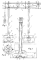
- the two supply devices 1 in FIG. 1 are connected to a feed loading system 2 and a water pipe 3 connected, which in turn screwed with the help of spacers 4 to a self-supporting component are and predominantly only from the branch lines 5 leading to the direct drinking tap 6 lead, are supported.
- An adjustable stop 14 shows on a scale 15 for the left feed storage container 7 in Fig. 1 the zero position and for the right feed storage container 7 the maximum position.
- Each feed storage container 7 hangs over a round trough 19 which is in its Center has an elevated storage area 20 which the feed storage container 7th lies opposite and together with the slide valve 8, which is a lattice ring 21 carries, the feed storage container closes when the slide 8 is in the closed position.
- a small piglet which is on with the front feet the raised step 23 in the trough 19 can put to the feed 22 on the raised Storage area 20 to arrive.
- a runner pig shown on the right is large enough to move from its location in front of trough 19 to one the direct drinking pin 6 to quench his thirst.
- a pointer 24 is slidably placed on the stub 5 where it is in the upper Area of the transparent feed storage container 7 at any point mark the fill level of the feed for control or testing purposes.
- the slide valve 8 can be designed as a thin tube, which is accordingly has a narrow edge as the bottom edge and moves downward through that as a pouring cone when opening the slide gate leaked food can move down to the storage surface 20.
- the closing movement is preferably carried out by gravity according to the corresponding Release of the main rope 12 by the actuator 13.
- a separate actuator can also be provided for each feed storage container 7 be provided, e.g. an electromotive, electromagnetic, hydraulic or pneumatic drive, the shutter 8 also in both Can actuate directions and a stroke adjustment allows.
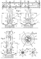
- a closure slide 31 surrounds the bottom all around the tubular feed storage container 32 and is via the pull rod 33 in point A with the lever 34 connected, which in turn is stored in point B and on the opposite End at point C via an elastic single rope 35 with a main rope 36 is connected, the straight from a crank actuator 37 in the largest stroke position is drawn.
- An adjustable stop 38 on a spacer 29 near point C. 4 for the left feed container 32 is at a minimum, so that none Feed 6 can leak.
- FIG. 5 shows the savings due to material shortening when the round trough 26 is increased by about the height of the concrete base 40, for example to the Components such as feeding space divider 41, central protection tube 42, tie rods 33 and Feed storage container 32.
- the round trough 26 has depressions on the outer underside for possible Feeding space divisions for example 6 x 60 ° (Fig. 6), 7 x 51.42 ° and 8 x 45 ° (Fig. 7), 9 x 40 ° and 10 x 36 ° on where the feeding space divider 41 with their screw connections 43 can be fixed.
- the labeling of the individual segments 41 ' is intended to clarify that the even distribution of the round trough 26 by the feeding space divider 41 alone already sufficient to ensure equal treatment of all animals in the feed supply.
- the slide valve 31 is a displacer trained who on his downward movement to the one below him Lining has an outward displacement effect. For this it has a cutting edge on the underside and one that slopes away from it Displacement surface 44 extending on the top outside.
- the lower surface preferably has Edge area of the slide slide 31 in the form of a chisel.
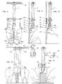
- the supply device exists in this further embodiment 1 again essentially from the tubular feed storage container 7, but with an offset transition piece in the lower area 50 is attached, which presents a flat lateral feed outlet opening 51, which can be closed as a closure member by means of a flat slide 52. Under there is a stowage surface 58 on the feed outlet opening 51 emerging feed 56 can put on.
- FIG. 8 shows a supply device 1 when the feed is being dispensed two animals 53a and 53b in a row.
- a symmetrical division of the Transition piece 50 in two feed pipes 54a and 54b ensures the Equality of the two feed portions 56a and 56b.
- Via a spiral conveyor 55 the feed storage container 2 is refilled here.
- Fig. 9 illustrates that when the shutter slide moves downward 52 a displacement of feed 56 takes place in the discharge chute 57 since the Locking slide 52 has an outer, here flat, displaceable inclined surface 44 having.
- Fig. 10 the slide gate 52 is moved up, with no feed falls into the chute 57.
- An animal 53b is drinking from a direct drinking tap 59, through a main line 60 and a branch line 61 receives the drinking water.
- a single rope 62a is connected to a single rope 62b, the end of it via a tension spring 63 with the main cable 64 leading to a crank actuator 65 leads, is connected.
- the slide valve 52 can only Carry out a smaller stroke a compared to crank stroke h.
- the stroke difference (h-a) is compensated for by the elasticity of the tension spring 63.
- a pull rope 68 leads from the single rope in the remote control 67 69 to a more distant setting location 70, where the Breakpoint 72 is adjusted.
- the dosage can be adjusted using the scale 73 be checked optically.
Landscapes
- Life Sciences & Earth Sciences (AREA)
- Environmental Sciences (AREA)
- Birds (AREA)
- Animal Husbandry (AREA)
- Biodiversity & Conservation Biology (AREA)
- Feeding And Watering For Cattle Raising And Animal Husbandry (AREA)
- Apparatuses For Bulk Treatment Of Fruits And Vegetables And Apparatuses For Preparing Feeds (AREA)
Claims (23)
- Appareil pour réguler l'alimentation d'animaux dans des emplacements d'alimentation individuels ou regroupés, avec un réservoir de stockage d'aliment en forme de tube ou de puits (7; 32) par emplacement d'alimentation individuel ou regroupé, dont l'extrémité inférieure est située à distance au-dessus d'une surface d'accumulation (20; 58) et peut être fermée, caractérisé en ce qu'il est prévu comme élément de fermeture un coulisseau de fermeture (8; 31; 52) affecté extérieurement à la partie d'extrémité inférieure du réservoir de stockage d'aliment (7; 32), ledit coulisseau pouvant être déplacé au moyen d'un vérin (13; 37; 65) entre une position de fermeture abaissée et une position d'ouverture relevée.
- Appareil selon la revendication 1, caractérisé en ce que le coulisseau de fermeture (8; 31) se présente sous la forme d'un coulisseau tubulaire adapté à la section transversale du réservoir de stockage d'aliment (7, 32).
- Appareil selon la revendication 1, caractérisé en ce que le coulisseau de fermeture (52) se présente sous la forme d'un coulisseau plat et est affecté à une ouverture de sortie d'aliment latérale (51) dans une pièce de transition (50) montée à l'extrémité inférieure du réservoir de stockage d'aliment (7).
- Appareil selon l'une quelconque des revendications 1 à 3, caractérisé en ce que le coulisseau de fermeture (31; 52) présente une zone de bord inférieure qui exerce sur l'alimentation située en dessous du coulisseau de fermeture un effet de déplacement dirigé vers l'extérieur lors d'un déplacement vers le bas.
- Appareil selon la revendication 4, caractérisé en ce que le coulisseau de fermeture (31; 52) présente dans sa partie inférieure une arête coupante et une surface de refoulement (44) s'étendant de celle-ci en oblique vers l'extérieur et le haut.
- Appareil selon la revendication 4 ou 5, caractérisé en ce que le bord inférieur du coulisseau de fermeture (31; 52) présente la forme d'un ciseau.
- Appareil selon l'une quelconque des revendications 1 à 6, caractérisé en ce que la direction de déplacement du coulisseau de fermeture (8; 31; 52) s'étend verticalement.
- Appareil selon ' l'une quelconque des revendications 1 à 7, caractérisé en ce que la course ascendante du coulisseau de fermeture (8; 31; 52) est réglable.
- Appareil selon l'une quelconque des revendications 1 à 8, caractérisé en ce que la course ascendante du coulisseau de fermeture (8; 31; 52) est, même à réglage maximal, plus petite que la hauteur de l'ouverture de sortie d'aliment à bloquer par le coulisseau de fermeture.
- Appareil selon l'une quelconque des revendications 1 à 9, caractérisé en ce que le coulisseau de fermeture (8; 31; 52) peut être re-déplacé d'une position d'ouverture provoquée par le vérin (13; 37; 65) dans sa position de fermeture par l'action de la pesanteur.
- Appareil selon l'une quelconque des revendications 1 à 10, caractérisé en ce qu'un vérin à commande indépendante est affecté à chaque coulisseau de fermeture (8; 31; 52).
- Appareil selon l'une quelconque des revendications 1 à 10, caractérisé en ce qu'à une pluralité de coulisseaux de fermeture (8; 31; 52) est affecté un vérin commun (13; 37; 65), dont le mouvement d'entraínement peut être transmis aux coulisseaux de fermeture (8; 31; 52) respectivement par des éléments de transmission d'entraínement (9, 10, 11, 12; 33, 34, 35, 36; 62, 63, 64).
- Appareil selon la revendication 12, caractérisé en ce qu'il est prévu comme éléments de transmission d'entraínement des câbles de traction (11, 12; 35, 36; 62, 64).
- Appareil selon la revendication 12 ou 13, caractérisé en ce qu'aux éléments de transmission d'entraínement (9, 10, 11, 12; 33, 34, 35, 36; 62, 63, 64) sont affectés des dispositifs de réglage (14; 38; 71, 72) pour le réglage uniforme individuel ou regroupé de la course ascendante des coulisseaux de fermeture (8; 31; 52).
- Appareil selon la revendication 13 ou 14, caractérisé en ce que les câbles de traction (11, 12; 35, 36; 62, 64) peuvent être commandés via des leviers (10; 34) et les dispositifs de réglage (14; 38) limitent la course pivotante des leviers (10; 34).
- Appareil selon l'une quelconque des revendications 1 à 15, caractérisé en ce que le vérin (13; 37; 65) ou selon le cas les vérins transfèrent le coulisseau de fermeture (8; 31; 52) ou selon le cas les coulisseaux de fermeture au cours d'un intervalle d'alimentation dans une position d'ouverture permanente.
- Appareil selon l'une quelconque des revendications 1 à 16, caractérisé en ce que le vérin (13; 37; 65) ou selon le cas les vérins communiquent au coulisseau de fermeture (8; 31; 52) ou selon le cas aux coulisseaux de fermeture au cours d'un intervalle d'alimentation une pluralité de déplacements d'ouverture et de fermeture.
- Appareil selon la revendication 16, caractérisé en ce que le coulisseau de fermeture (8; 31; 52) ou selon le cas les coulisseaux de fermeture constituent un moyen de répartition dosée de l'alimentation, qui est dimensionné en fonction des courses ascendantes et des nombres de courses.
- Appareil selon l'une quelconque des revendications 1 à 18, caractérisé en ce que le coulisseau de fermeture (8; 31; 52) est protégé extérieurement par une pièce de protection fixe (42; 50).
- Appareil selon l'une quelconque des revendications 1 à 19, caractérisé en ce que le coulisseau de fermeture (8; 31; 52) est constitué de plusieurs parties, qui ferment ou libèrent respectivement une ouverture partielle et peuvent être commandés indépendamment l'un de l'autre ou conjointement.
- Appareil selon l'une quelconque des revendications 1 à 20, caractérisé en ce que la surface d'accumulation (20) est formée par une zone centrale surélevée d'une auge (19; 26), en particulier d'une auge ronde.
- Appareil selon la revendication 21, caractérisé en ce que l'auge (19; 26) présente dans la zone creuse comprise entre la position la plus profonde et le bord extérieur une surface d'appui sensiblement horizontale (23) pour les pattes avant de petits animaux (22).
- Appareil selon l'une quelconque des revendications 3 à 20, caractérisé en ce que la surface d'accumulation (58) fait partie de la pièce de transition (50) ou est agencée sur celle-ci par la suite.
Applications Claiming Priority (4)
| Application Number | Priority Date | Filing Date | Title |
|---|---|---|---|
| DE19617784 | 1996-05-05 | ||
| DE19617786 | 1996-05-05 | ||
| DE1996117784 DE19617784A1 (de) | 1996-05-05 | 1996-05-05 | Versorgungseinrichtung für Tiergruppen |
| DE1996117786 DE19617786A1 (de) | 1996-05-05 | 1996-05-05 | Streßreduzierende Versorgungseinrichtung an Einzel- und Gruppenfreßplätzen |
Publications (2)
| Publication Number | Publication Date |
|---|---|
| EP0806136A1 EP0806136A1 (fr) | 1997-11-12 |
| EP0806136B1 true EP0806136B1 (fr) | 2001-06-13 |
Family
ID=26025365
Family Applications (1)
| Application Number | Title | Priority Date | Filing Date |
|---|---|---|---|
| EP97107405A Expired - Lifetime EP0806136B1 (fr) | 1996-05-05 | 1997-05-05 | Appareil pour réguler l'alimentation d'animaux |
Country Status (3)
| Country | Link |
|---|---|
| EP (1) | EP0806136B1 (fr) |
| AT (1) | ATE201955T1 (fr) |
| DE (1) | DE59703755D1 (fr) |
Families Citing this family (4)
| Publication number | Priority date | Publication date | Assignee | Title |
|---|---|---|---|---|
| NL1010898C2 (nl) * | 1998-12-24 | 2000-06-27 | Lely Research Holding Ag | Voerzuil en/of drinkzuil voor het voederen van dieren. |
| NL1011799C2 (nl) * | 1998-12-24 | 2000-06-27 | Lely Research Holding Ag | Inrichting voor het voeren en/of drenken van dieren. |
| AT523151B1 (de) * | 2020-03-11 | 2021-06-15 | Avl List Gmbh | Drehschalter |
| CN113575487B (zh) * | 2021-09-14 | 2023-03-21 | 大连国富水产食品有限公司 | 一种水产养殖用自动喂料装置 |
Family Cites Families (6)
| Publication number | Priority date | Publication date | Assignee | Title |
|---|---|---|---|---|
| US3855971A (en) * | 1973-12-27 | 1974-12-24 | R Hess | Combination granary and feeder for livestock |
| DE2509954B2 (de) * | 1975-03-07 | 1976-11-18 | Eichholz, Heinz, 4441 Schapen | Einrichtung zur befuellung von futterstellen |
| US4040389A (en) * | 1975-09-12 | 1977-08-09 | Walters James H | Animal feeding device |
| FR2513072B1 (fr) * | 1981-09-18 | 1987-05-29 | Inst Tech Porc | Reservoir en materiau stratifie destine a contenir et distribuer, grace a un dispositif de reglage precis du debit, un aliment a des animaux defonceurs tels que des porcs et associable a d'autres reservoirs identiques afin de constituer une cloison de parc |
| US4770124A (en) * | 1987-01-12 | 1988-09-13 | Dubbe Ronald F | Timed feeding system for dairy cattle |
| NL8900054A (nl) * | 1989-01-10 | 1990-08-01 | Kunststoffenbedrijf Azer B V | Door het vee bedienbare veevoedervoorraadbak. |
-
1997
- 1997-05-05 AT AT97107405T patent/ATE201955T1/de not_active IP Right Cessation
- 1997-05-05 DE DE59703755T patent/DE59703755D1/de not_active Expired - Fee Related
- 1997-05-05 EP EP97107405A patent/EP0806136B1/fr not_active Expired - Lifetime
Also Published As
| Publication number | Publication date |
|---|---|
| EP0806136A1 (fr) | 1997-11-12 |
| DE59703755D1 (de) | 2001-07-19 |
| ATE201955T1 (de) | 2001-06-15 |
Similar Documents
| Publication | Publication Date | Title |
|---|---|---|
| DE69002574T2 (de) | Einstellbare Füttervorrichtung für Geflügel. | |
| US3901194A (en) | Apparatus for mixing and dispensing feed to animals | |
| DE2639423A1 (de) | Verfahren und einrichtung zum fuettern von haustieren | |
| EP0806136B1 (fr) | Appareil pour réguler l'alimentation d'animaux | |
| DE60224606T2 (de) | Vorrichtung zum Zuführen von Futter zu Tieren | |
| EP3598893B1 (fr) | Doseur volumétrique, installation d'alimentation pour animaux et procédé de fourniture de l'aliment pour animaux | |
| DD152463A5 (de) | Verfahren und vorrichtung zum fuettern einer mehrzahl von nichtangebundenen tieren | |
| DE4242188C2 (de) | Dribbeleinrichtung für Trockenfutter | |
| DE2509954A1 (de) | Einrichtung zur befuellung von futterstellen | |
| DE1182462B (de) | Vorrichtung zum Fuettern von zu maestenden Tieren mit Getreideschrot od. dgl., insbesondere fuer Schweine | |
| DE2652884C3 (de) | Viehfütterungs-Vorrichtung | |
| EP0326636B1 (fr) | Dispositif d'alimentation en produits à peser pour balances de remplissage | |
| DE202018104323U1 (de) | Volumendosierer und Fütterungsanlage | |
| DE8806165U1 (de) | Vorrichtung zur Zuführung einer Futterdosis von einem Förderer zu einem Futtertrog | |
| DE3805149C1 (en) | Arrangement for charging feed places or troughs | |
| DE2750163A1 (de) | Einrichtung zur fuetterung von tieren | |
| EP2242355A1 (fr) | Système d'affouragement automatique, en particulier pour chevaux | |
| DE1966710C3 (de) | Eiersammelvorrichtung | |
| DE19718076C2 (de) | Selbstmixfütterer | |
| DE29700720U1 (de) | Fütterungsvorrichtung, insbesondere für die Fütterung von Ferkeln | |
| DE2402645A1 (de) | Futterautomat fuer schweine | |
| DE3304366C1 (de) | Einrichtung zum Befüllen von Futterstellen | |
| DE1205756B (de) | Voll- oder halbautomatisch arbeitende Einrichtung zur gewichtsdosierten Fuetterung von z. B. Schweinen | |
| DE3438597A1 (de) | Verfahren und vorrichtung zur zuteilung von futter | |
| DE4316397A1 (de) | Verfahren und Anordnung zum Füttern von Rindern in Großviehanlagen |
Legal Events
| Date | Code | Title | Description |
|---|---|---|---|
| PUAI | Public reference made under article 153(3) epc to a published international application that has entered the european phase |
Free format text: ORIGINAL CODE: 0009012 |
|
| AK | Designated contracting states |
Kind code of ref document: A1 Designated state(s): AT BE DE DK ES FR GB GR IE IT NL SE |
|
| 17P | Request for examination filed |
Effective date: 19980109 |
|
| RBV | Designated contracting states (corrected) |
Designated state(s): AT BE DE DK ES FR GB GR IE IT NL SE |
|
| 17Q | First examination report despatched |
Effective date: 19991020 |
|
| GRAG | Despatch of communication of intention to grant |
Free format text: ORIGINAL CODE: EPIDOS AGRA |
|
| GRAG | Despatch of communication of intention to grant |
Free format text: ORIGINAL CODE: EPIDOS AGRA |
|
| GRAH | Despatch of communication of intention to grant a patent |
Free format text: ORIGINAL CODE: EPIDOS IGRA |
|
| GRAH | Despatch of communication of intention to grant a patent |
Free format text: ORIGINAL CODE: EPIDOS IGRA |
|
| GRAA | (expected) grant |
Free format text: ORIGINAL CODE: 0009210 |
|
| AK | Designated contracting states |
Kind code of ref document: B1 Designated state(s): AT BE DE DK ES FR GB GR IE IT NL SE |
|
| PG25 | Lapsed in a contracting state [announced via postgrant information from national office to epo] |
Ref country code: NL Free format text: LAPSE BECAUSE OF FAILURE TO SUBMIT A TRANSLATION OF THE DESCRIPTION OR TO PAY THE FEE WITHIN THE PRESCRIBED TIME-LIMIT Effective date: 20010613 Ref country code: IT Free format text: LAPSE BECAUSE OF FAILURE TO SUBMIT A TRANSLATION OF THE DESCRIPTION OR TO PAY THE FEE WITHIN THE PRE;WARNING: LAPSES OF ITALIAN PATENTS WITH EFFECTIVE DATE BEFORE 2007 MAY HAVE OCCURRED AT ANY TIME BEFORE 2007. THE CORRECT EFFECTIVE DATE MAY BE DIFFERENT FROM THE ONE RECORDED.SCRIBED TIME-LIMIT Effective date: 20010613 Ref country code: IE Free format text: LAPSE BECAUSE OF FAILURE TO SUBMIT A TRANSLATION OF THE DESCRIPTION OR TO PAY THE FEE WITHIN THE PRESCRIBED TIME-LIMIT Effective date: 20010613 Ref country code: GB Free format text: LAPSE BECAUSE OF FAILURE TO SUBMIT A TRANSLATION OF THE DESCRIPTION OR TO PAY THE FEE WITHIN THE PRESCRIBED TIME-LIMIT Effective date: 20010613 Ref country code: FR Free format text: LAPSE BECAUSE OF FAILURE TO SUBMIT A TRANSLATION OF THE DESCRIPTION OR TO PAY THE FEE WITHIN THE PRESCRIBED TIME-LIMIT Effective date: 20010613 |
|
| REF | Corresponds to: |
Ref document number: 201955 Country of ref document: AT Date of ref document: 20010615 Kind code of ref document: T |
|
| REF | Corresponds to: |
Ref document number: 59703755 Country of ref document: DE Date of ref document: 20010719 |
|
| REG | Reference to a national code |
Ref country code: IE Ref legal event code: FG4D Free format text: GERMAN |
|
| PG25 | Lapsed in a contracting state [announced via postgrant information from national office to epo] |
Ref country code: SE Free format text: LAPSE BECAUSE OF FAILURE TO SUBMIT A TRANSLATION OF THE DESCRIPTION OR TO PAY THE FEE WITHIN THE PRESCRIBED TIME-LIMIT Effective date: 20010913 Ref country code: DK Free format text: LAPSE BECAUSE OF FAILURE TO SUBMIT A TRANSLATION OF THE DESCRIPTION OR TO PAY THE FEE WITHIN THE PRESCRIBED TIME-LIMIT Effective date: 20010913 |
|
| PG25 | Lapsed in a contracting state [announced via postgrant information from national office to epo] |
Ref country code: GR Free format text: LAPSE BECAUSE OF FAILURE TO SUBMIT A TRANSLATION OF THE DESCRIPTION OR TO PAY THE FEE WITHIN THE PRESCRIBED TIME-LIMIT Effective date: 20010914 |
|
| NLV1 | Nl: lapsed or annulled due to failure to fulfill the requirements of art. 29p and 29m of the patents act | ||
| GBV | Gb: ep patent (uk) treated as always having been void in accordance with gb section 77(7)/1977 [no translation filed] |
Effective date: 20010613 |
|
| PG25 | Lapsed in a contracting state [announced via postgrant information from national office to epo] |
Ref country code: ES Free format text: LAPSE BECAUSE OF FAILURE TO SUBMIT A TRANSLATION OF THE DESCRIPTION OR TO PAY THE FEE WITHIN THE PRESCRIBED TIME-LIMIT Effective date: 20011220 |
|
| EN | Fr: translation not filed | ||
| REG | Reference to a national code |
Ref country code: IE Ref legal event code: FD4D |
|
| PLBE | No opposition filed within time limit |
Free format text: ORIGINAL CODE: 0009261 |
|
| STAA | Information on the status of an ep patent application or granted ep patent |
Free format text: STATUS: NO OPPOSITION FILED WITHIN TIME LIMIT |
|
| PG25 | Lapsed in a contracting state [announced via postgrant information from national office to epo] |
Ref country code: AT Free format text: LAPSE BECAUSE OF NON-PAYMENT OF DUE FEES Effective date: 20020505 |
|
| PG25 | Lapsed in a contracting state [announced via postgrant information from national office to epo] |
Ref country code: BE Free format text: LAPSE BECAUSE OF NON-PAYMENT OF DUE FEES Effective date: 20020531 |
|
| 26N | No opposition filed | ||
| PG25 | Lapsed in a contracting state [announced via postgrant information from national office to epo] |
Ref country code: DE Free format text: LAPSE BECAUSE OF NON-PAYMENT OF DUE FEES Effective date: 20021203 |