EP0806136B1 - Apparatus for regulating feeding of animals - Google Patents
Apparatus for regulating feeding of animals Download PDFInfo
- Publication number
- EP0806136B1 EP0806136B1 EP97107405A EP97107405A EP0806136B1 EP 0806136 B1 EP0806136 B1 EP 0806136B1 EP 97107405 A EP97107405 A EP 97107405A EP 97107405 A EP97107405 A EP 97107405A EP 0806136 B1 EP0806136 B1 EP 0806136B1
- Authority
- EP
- European Patent Office
- Prior art keywords
- sliding shutter
- feed
- sliding
- storage container
- shutter
- Prior art date
- Legal status (The legal status is an assumption and is not a legal conclusion. Google has not performed a legal analysis and makes no representation as to the accuracy of the status listed.)
- Expired - Lifetime
Links
- 241001465754 Metazoa Species 0.000 title claims description 14
- 230000001105 regulatory effect Effects 0.000 title 1
- 230000005484 gravity Effects 0.000 claims abstract description 3
- 238000003860 storage Methods 0.000 claims description 29
- 238000005520 cutting process Methods 0.000 claims description 3
- 239000000470 constituent Substances 0.000 claims 1
- 238000006073 displacement reaction Methods 0.000 abstract description 6
- 230000035622 drinking Effects 0.000 description 4
- 125000006850 spacer group Chemical group 0.000 description 3
- 238000000034 method Methods 0.000 description 2
- 230000007704 transition Effects 0.000 description 2
- XLYOFNOQVPJJNP-UHFFFAOYSA-N water Substances O XLYOFNOQVPJJNP-UHFFFAOYSA-N 0.000 description 2
- 238000010276 construction Methods 0.000 description 1
- 238000009826 distribution Methods 0.000 description 1
- 239000003651 drinking water Substances 0.000 description 1
- 235000020188 drinking water Nutrition 0.000 description 1
- 230000000694 effects Effects 0.000 description 1
- 235000021050 feed intake Nutrition 0.000 description 1
- 244000144993 groups of animals Species 0.000 description 1
- 238000002372 labelling Methods 0.000 description 1
- 239000000463 material Substances 0.000 description 1
- 238000010791 quenching Methods 0.000 description 1
- 230000000384 rearing effect Effects 0.000 description 1
- 238000004904 shortening Methods 0.000 description 1
- 230000035922 thirst Effects 0.000 description 1
Images
Classifications
-
- A—HUMAN NECESSITIES
- A01—AGRICULTURE; FORESTRY; ANIMAL HUSBANDRY; HUNTING; TRAPPING; FISHING
- A01K—ANIMAL HUSBANDRY; AVICULTURE; APICULTURE; PISCICULTURE; FISHING; REARING OR BREEDING ANIMALS, NOT OTHERWISE PROVIDED FOR; NEW BREEDS OF ANIMALS
- A01K5/00—Feeding devices for stock or game ; Feeding wagons; Feeding stacks
- A01K5/02—Automatic devices
- A01K5/0275—Automatic devices with mechanisms for delivery of measured doses
Definitions
- the invention relates to a device for feeding animals to individual animals. and / or group eating places in a configuration according to the preamble of claim 1.
- a device for feeding animals to individual animals. and / or group eating places in a configuration according to the preamble of claim 1.
- Such a device is known from the Document US-A-4 770 124.
- the feed storage containers are each adjustable up and down by hand using a lever and on the Storage area can be set down and thus locked.
- Such a configuration requires a high level of positioning effort, which goes hand in hand with corresponding positioning forces, because the entire feed storage container has to be moved.
- the invention is concerned with the problem of a device of the aforementioned Type to create a simple and reliable with little construction effort Operation enables and can be used for different types of feeding is.
- an external slide valve and an actuator for this it allows to feed in at predetermined feeding times release any but also dosed amount for consumption for the animals, with only a small amount of force for the actuation of the slide gate is required, which can be provided with simple drive means can.
- the facility is easy to control and is capable of ad libitum feeding as well as a dribble feeding.
- the slide valve can be used during a feeding period be opened and closed repeatedly, each time by closing the slide a leaked when opening Amount of feed is divided and exposed to feed intake.
- the opening process escaping and separable when closing the slide The amount of feed depends on the design-related, releasable opening size starting by adjusting the stroke of the slide gate is limited.
- the number of strokes covered is also a determining factor during a feeding period.
- Feed can be fed, it can be ensured that all animals, too within a group, the intended feed at the same time, continuously and / or adjusted in quantity, so that the animals during the rearing or fattening are optimally available. Since when completed Feed storage container prevents further release of feed can be ensured be that the troughs in the forced breaks between a feed release be completely emptied by the animals so that the animals always fresh feed from troughs is presented, for hygienic reasons health care is desirable.
- the two supply devices 1 in FIG. 1 are connected to a feed loading system 2 and a water pipe 3 connected, which in turn screwed with the help of spacers 4 to a self-supporting component are and predominantly only from the branch lines 5 leading to the direct drinking tap 6 lead, are supported.
- An adjustable stop 14 shows on a scale 15 for the left feed storage container 7 in Fig. 1 the zero position and for the right feed storage container 7 the maximum position.
- Each feed storage container 7 hangs over a round trough 19 which is in its Center has an elevated storage area 20 which the feed storage container 7th lies opposite and together with the slide valve 8, which is a lattice ring 21 carries, the feed storage container closes when the slide 8 is in the closed position.
- a small piglet which is on with the front feet the raised step 23 in the trough 19 can put to the feed 22 on the raised Storage area 20 to arrive.
- a runner pig shown on the right is large enough to move from its location in front of trough 19 to one the direct drinking pin 6 to quench his thirst.
- a pointer 24 is slidably placed on the stub 5 where it is in the upper Area of the transparent feed storage container 7 at any point mark the fill level of the feed for control or testing purposes.
- the slide valve 8 can be designed as a thin tube, which is accordingly has a narrow edge as the bottom edge and moves downward through that as a pouring cone when opening the slide gate leaked food can move down to the storage surface 20.
- the closing movement is preferably carried out by gravity according to the corresponding Release of the main rope 12 by the actuator 13.
- a separate actuator can also be provided for each feed storage container 7 be provided, e.g. an electromotive, electromagnetic, hydraulic or pneumatic drive, the shutter 8 also in both Can actuate directions and a stroke adjustment allows.
- a closure slide 31 surrounds the bottom all around the tubular feed storage container 32 and is via the pull rod 33 in point A with the lever 34 connected, which in turn is stored in point B and on the opposite End at point C via an elastic single rope 35 with a main rope 36 is connected, the straight from a crank actuator 37 in the largest stroke position is drawn.
- An adjustable stop 38 on a spacer 29 near point C. 4 for the left feed container 32 is at a minimum, so that none Feed 6 can leak.
- FIG. 5 shows the savings due to material shortening when the round trough 26 is increased by about the height of the concrete base 40, for example to the Components such as feeding space divider 41, central protection tube 42, tie rods 33 and Feed storage container 32.
- the round trough 26 has depressions on the outer underside for possible Feeding space divisions for example 6 x 60 ° (Fig. 6), 7 x 51.42 ° and 8 x 45 ° (Fig. 7), 9 x 40 ° and 10 x 36 ° on where the feeding space divider 41 with their screw connections 43 can be fixed.
- the labeling of the individual segments 41 ' is intended to clarify that the even distribution of the round trough 26 by the feeding space divider 41 alone already sufficient to ensure equal treatment of all animals in the feed supply.
- the slide valve 31 is a displacer trained who on his downward movement to the one below him Lining has an outward displacement effect. For this it has a cutting edge on the underside and one that slopes away from it Displacement surface 44 extending on the top outside.
- the lower surface preferably has Edge area of the slide slide 31 in the form of a chisel.
- the supply device exists in this further embodiment 1 again essentially from the tubular feed storage container 7, but with an offset transition piece in the lower area 50 is attached, which presents a flat lateral feed outlet opening 51, which can be closed as a closure member by means of a flat slide 52. Under there is a stowage surface 58 on the feed outlet opening 51 emerging feed 56 can put on.
- FIG. 8 shows a supply device 1 when the feed is being dispensed two animals 53a and 53b in a row.
- a symmetrical division of the Transition piece 50 in two feed pipes 54a and 54b ensures the Equality of the two feed portions 56a and 56b.
- Via a spiral conveyor 55 the feed storage container 2 is refilled here.
- Fig. 9 illustrates that when the shutter slide moves downward 52 a displacement of feed 56 takes place in the discharge chute 57 since the Locking slide 52 has an outer, here flat, displaceable inclined surface 44 having.
- Fig. 10 the slide gate 52 is moved up, with no feed falls into the chute 57.
- An animal 53b is drinking from a direct drinking tap 59, through a main line 60 and a branch line 61 receives the drinking water.
- a single rope 62a is connected to a single rope 62b, the end of it via a tension spring 63 with the main cable 64 leading to a crank actuator 65 leads, is connected.
- the slide valve 52 can only Carry out a smaller stroke a compared to crank stroke h.
- the stroke difference (h-a) is compensated for by the elasticity of the tension spring 63.
- a pull rope 68 leads from the single rope in the remote control 67 69 to a more distant setting location 70, where the Breakpoint 72 is adjusted.
- the dosage can be adjusted using the scale 73 be checked optically.
Landscapes
- Life Sciences & Earth Sciences (AREA)
- Environmental Sciences (AREA)
- Birds (AREA)
- Animal Husbandry (AREA)
- Biodiversity & Conservation Biology (AREA)
- Feeding And Watering For Cattle Raising And Animal Husbandry (AREA)
- Apparatuses For Bulk Treatment Of Fruits And Vegetables And Apparatuses For Preparing Feeds (AREA)
Abstract
Description
Die Erfindung betrifft eine Einrichtung zur Futterversorgung von Tieren an Einzel-
und/oder Gruppenfreßplätzen in einer Ausgestaltung gemäß dem Oberbegriff
des Anspruchs 1. Solch eine Einrichtung ist bekannt aus dem
Dokument US-A-4 770 124.The invention relates to a device for feeding animals to individual animals.
and / or group eating places in a configuration according to the preamble
of
Bei einer bekannten Einrichtung dieser Art (Dokument FR-A-2 513 072) sind die Futtervorratsbehälter jeweils mittels eines Hebels von Hand auf und ab verstellbar und auf der Staufläche absetz- und dadurch verschließbar. Eine solche Ausgestaltung erfordert einen hohen Stellaufwand, der mit entsprechenden Stellkräften einhergeht, da der gesamte Futtervorratsbehälter zu bewegen ist.In a known device of this type (document FR-A-2 513 072), the feed storage containers are each adjustable up and down by hand using a lever and on the Storage area can be set down and thus locked. Such a configuration requires a high level of positioning effort, which goes hand in hand with corresponding positioning forces, because the entire feed storage container has to be moved.
Die Erfindung befaßt sich mit dem Problem, eine Einrichtung der genannten Art zu schaffen, die bei geringem baulichen Aufwand eine einfache und zuverlässige Bedienung ermöglicht und für unterschiedliche Fütterungsarten einsetzbar ist.The invention is concerned with the problem of a device of the aforementioned Type to create a simple and reliable with little construction effort Operation enables and can be used for different types of feeding is.
Die Erfindung löst dieses Problem durch eine Einrichtung mit den Merkmalen
des Anspruchs 1. Hinsichtlich wesentlicher weiterer Ausgestaltungen wird auf
die Ansprüche 2 bis 23 verwiesen.The invention solves this problem by a device with the features
of
Das Vorsehen eines außenliegenden Verschlußschiebers und eines Stellantriebes für diesen ermöglicht es, zu vorgegebenen Fütterungszeiten Futter in beliebiger aber auch dosierter Menge zum Verzehr für die Tiere freizugeben, wobei lediglich ein geringer Kraftaufwand für die Betätigung des Verschlußschiebers erforderlich ist, der mit einfachen Antriebsmitteln erbracht werden kann. Dabei ist die Einrichtung einfach steuerbar und in der Lage, eine ad libitum-Fütterung ebenso zu verwirklichen wie eine Dribbelfütterung. The provision of an external slide valve and an actuator for this it allows to feed in at predetermined feeding times release any but also dosed amount for consumption for the animals, with only a small amount of force for the actuation of the slide gate is required, which can be provided with simple drive means can. The facility is easy to control and is capable of ad libitum feeding as well as a dribble feeding.
Zu Dosierungszwecken kann der Verschlußschieber während eines Fütterungszeitraumes wiederholt geöffnet und geschlossen werden, wobei jeweils durch Schließen des Verschlußschiebers eine bei dessen Öffnen ausgetretene Futtermenge abgeteilt wird und zur Futteraufnahme freiliegt. Die je Öffnungsvorgang austretende und beim Schließen des Verschlußschiebers abteilbare Futtermenge hängt dabei von der konstruktiv bedingten freigebbaren Öffnungsgröße ab, die durch Einstellung des Hubweges des Verschlußschiebers begrenzbar ist. Mitbestimmend ist ferner die Zahl der zurückgelegten Hübe während eines Fütterungszeitraumes. Bei der Dribbelfütterung mit einem als Verdränger wirksamen Verschlußschieber werden stets nur kleine Mengen abgeteilt und zum Fressen freigegeben, wobei sich dieser Vorgang während eines Fütterungszeitraumes üblicherweise vielfach wiederholt. Bei entsprechender Steuerung der Einrichtung, die üblicherweise eine Mehrzahl von Futtervorratsbehältern umfaßt, die oberseitig mitttels eines Futterförderers mit Futter beschickbar sind, kann sichergestellt werden, daß allen Tieren, auch innerhalb einer Gruppe, das vorgesehene Futter zeitgleich, kontinuierlich und/oder mengenangepaßt vorgelegt werden kann, so daß die Tiere während der Aufzucht bzw. Mast optimal versorgbar sind. Da bei abgeschlossenem Futtervorratsbehälter eine weitere Freigabe von Futter verhindert ist, kann sichergestellt werden, daß die Tröge in den Zwangspausen zwischen einer Futterfreigabe von den Tieren vollständig geleert werden, so daß den Tieren stets frisches Futter aus Trögen dargeboten wird, was aus hygienischen Gründen zur Gesundheitsvorsorge erwünscht ist.For dosing purposes, the slide valve can be used during a feeding period be opened and closed repeatedly, each time by closing the slide a leaked when opening Amount of feed is divided and exposed to feed intake. The opening process escaping and separable when closing the slide The amount of feed depends on the design-related, releasable opening size starting by adjusting the stroke of the slide gate is limited. The number of strokes covered is also a determining factor during a feeding period. When dribbling with an as Only small amounts of displacement slider are effective partitioned and released to eat, this process during of a feeding period usually repeated many times. With appropriate Control of the facility, which is usually a plurality of feed storage containers includes the top by means of a feed conveyor Feed can be fed, it can be ensured that all animals, too within a group, the intended feed at the same time, continuously and / or adjusted in quantity, so that the animals during the rearing or fattening are optimally available. Since when completed Feed storage container prevents further release of feed can be ensured be that the troughs in the forced breaks between a feed release be completely emptied by the animals so that the animals always fresh feed from troughs is presented, for hygienic reasons health care is desirable.
Weitere Einzelheiten und Vorteile ergeben sich aus der nachfolgenden Beschreibung und der Zeichnung, in der mehrere Ausführungsbeispiele des Gegenstandes der Erfindung näher veranschaulicht sind. Im einzelnen zeigen:
- Fig. 1
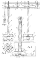
- eine Einrichtung nach der Erfindung in Seitenansicht in einem zur Versorgung von zwei Tiergruppen veranschaulichenden Ausschnitt,
- Fig. 2
- eine Draufsicht auf den unteren Teil eines Futtervorratsbehälters mit darunter befindlichem Rundtrog,
- Fig. 3
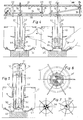
- eine vergrößerte Darstellung eines Futtervorratsbehälters im Aufriß,
- Fig. 4
- eine Seitenansicht, teilweise im Schnitt, ähnlich Fig. 1 zur Veranschaulichung einer zweiten Ausführung der Einrichtung nach der Erfindung,
- Fig. 5
- einen einzelnen Futtervorratsbehälter zur Veranschaulichung des als Verdränger ausgebildeten Verschlußschiebers im Schnitt,
- Fig. 6
- eine vereinfachte Draufsicht zu Fig. 5,
- Fig. 7
- vereinfachte Draufsichten ähnlich Fig. 6 zur Veranschaulichung unterschiedlicher Aufteilungen des Trogbereiches in Freßplätze,
- Fig. 8
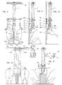
- eine Seitenansicht einer Einrichtung nach der Erfindung in einer dritten Ausführung für die Versorgung von zwei Tieren in Reihenaufstallung,
- Fig. 9
- eine Seitenansicht der Einrichtung nach Fig. 8 in einer Blickrichtung unter rechtem Winkel zu der nach Fig. 8 bei abgesenktem Verschlußschieber,
- Fig. 10
- eine Darstellung der Einrichtung entsprechend Fig. 9 bei angehobenem Verschlußschieber,
- Fig. 11
- eine Darstellung einer vierten Ausführung einer Einrichtung nach der Erfindung für eine Einzelplatzversorgung, und
- Fig. 12
- eine Ansicht der Einrichtung nach Fig. 11 in einer Blickrichtung unter rechtem Winkel zu der nach Fig. 11.
- Fig. 1
- FIG. 2 shows a device according to the invention in a side view in a section that illustrates two groups of animals,
- Fig. 2
- a plan view of the lower part of a feed storage container with a round trough underneath,
- Fig. 3
- an enlarged view of a feed storage container in elevation,
- Fig. 4
- 2 shows a side view, partly in section, similar to FIG. 1 to illustrate a second embodiment of the device according to the invention,
- Fig. 5
- a single feed storage container to illustrate the slide formed as a displacer in section,
- Fig. 6
- a simplified top view of Fig. 5,
- Fig. 7
- 6 Simplified top views similar to FIG. 6 to illustrate different division of the trough area into feeding places.
- Fig. 8
- a side view of a device according to the invention in a third embodiment for the care of two animals in a row,
- Fig. 9
- 8 shows a side view of the device according to FIG. 8 in a viewing direction at a right angle to that according to FIG. 8 with the closure slide lowered,
- Fig. 10
- 9 shows the device corresponding to FIG. 9 with the slide slide raised,
- Fig. 11
- a representation of a fourth embodiment of a device according to the invention for a single station supply, and
- Fig. 12
- 11 in a viewing direction at a right angle to that of FIG. 11th
Die beiden Versorgungseinrichtungen 1 in der Fig. 1 sind an eine Futterbeschickungsanlage
2 und eine Wasserleitung 3 angeschlossen, die ihrerseits
mit Hilfe von Distanzhaltern 4 zu einem freitragenden Bauelement verschraubt
sind und überwiegend nur von den Stichleitungen 5, die zu den Direkttränkezapfen
6 führen, abgestützt sind.The two
Ein Futtervorratsbehälter 7, der rohr- oder schachtförmig ausgebildet ist und
runden oder eckigen Querschnitt haben kann, hängt jeweils an der Futterbeschickungsanlage
2 und ragt unten in einen durchmessergrößeren, hier ebenfalls
rohrförmigen Verschlußschieber 8, der über das Zuggestänge 9 im Punkt
A mit einem Hebel 10 verbunden ist, der seinerseits im Punkt B gelagert und
am entgegengesetzten Ende im Punkt C über ein elastisches Einzelseil 11 mit
einem Hauptseil 12 gekoppelt ist, das gerade von einem zentralen Stellantrieb
13 in AUF-Position gezogen worden ist.A
Ein verstellbarer Anschlag 14 zeigt auf einer Skala 15 für den linken Futtervorratsbehälter
7 in Fig. 1 die Null-Position und für den rechten Futtervorratsbehälter
7 die Maximum-Position an. An
Die Freßplatzteiler 16 an den Bodenstativen 17, die über die Streben 18 verbunden
sind, geben der Versorgungseinrichtung 1 die notwendige Standfestigkeit.The feeding
Jeder Futtervorratsbehälter 7 hängt über einem Rundtrog 19, der in seinem
Zentrum eine erhöhte Staufläche 20 aufweist, die dem Futtervorratsbehälter 7
gegenüberliegt und zusammen mit dem Verschlußschieber 8, der einen Gitterring
21 trägt, den Futtervorratsbehälter abschließt, wenn sich der Verschlußschieber
8 in Schließstellung befindet.Each
In Fig. 2 erkennt man in der Draufsicht einen Rundtrog 19, der viele Freßplätze
zwischen den Freßplatzteilern 16 in gleicher Entfernung zur zentralen Staufläche
20 bietet.In Fig. 2 you can see in the plan view a
In Fig. 3 sieht man links ein kleines Ferkel, das sich mit den Vorderfüßen auf
die erhöhte Stufe 23 im Trog 19 stellen kann, um an das Futter 22 auf der erhöhten
Staufläche 20 zu gelangen. Ein rechts dargestelltes Läuferschwein hingegen
ist groß genug, um von seinem Standort vor dem Trog 19 noch an einem
der Direkttränkezapfen 6 seinen Durst löschen zu können.In Fig. 3 you can see on the left a small piglet, which is on with the front feet
the raised
Ein Stellzeiger 24 ist verschiebbar auf der Stichleitung 5 plaziert, wo er im oberen
Bereich des durchsichtigen Futtervorratsbehälters 7 an beliebiger Stelle
den Füllstand des Futters für Kontroll- oder Prüfzwecke markieren soll.A
Der Verschlußschieber 8 kann als dünnes Rohr ausgebildet sein, das dementsprechend
einen schmalen Rand als Unterkante darbietet und sich bei Abwärtsbewegung
durch das als Schüttkegel beim Öffnen des Verschlußschiebers
ausgetretene Futter bis herab zur Staufläche 20 hindurchbewegen kann. The
Die Schließbewegung erfolgt vorzugsweise durch Schwerkraft nach entsprechender
Freigabe des Hauptseils 12 durch den Stellantrieb 13. Grundsätzlich
kann jedoch auch für jeden Futtervorratsbehälter 7 ein gesonderter Stellantrieb
vorgesehen sein, z.B. ein elektromotorischer, elektromagnetischer, hydraulischer
oder pneumatischer Antrieb, der den Verschlußschieber 8 auch in beiden
Richtungen betätigen kann und eine Hubwegeinstellung erlaubt.The closing movement is preferably carried out by gravity according to the corresponding
Release of the
Bei der Ausführung nach Fig. 4 werden die Versorgungseinrichtungen 25 mit
Rundtrog 26 über die Wasserleitung 27 und Futterleitung 28 beschickt, die mit
Hilfe von Distanzhaltern 29 in bestimmtem Abstand parallel zu einem freitragenden
Bauelement verschraubt sind und überwiegend nur von den beiden
Stichleitungen 30 abgestützt werden.4, the
Ein Verschlußschieber 31 umgibt unten rundum den rohrförmigen Futtervorratsbehälter
32 und ist über das Zuggestänge 33 im Punkt A mit dem Hebel 34
verbunden, der seinerseits im Punkt B gelagert und am entgegengesetzten
Ende im Punkt C über ein elastisches Einzelseil 35 mit einem Hauptseil 36
verbunden ist, das gerade von einem Kurbel-Stellantrieb 37 in größte Hubstellung
gezogen ist.A
Ein verstellbarer Anschlag 38 an einem Distanzhalter 29 nahe dem Punkt C
steht in Fig. 4 für den linken Futtervorratsbehälter 32 auf Minimum, so daß kein
Futter 6 austreten kann.An
Beim Futtervorratsbehälter rechts in Fig. 4 hingegen ist der Anschlag 38 auf
Maximum eingestellt, was auf der Skala 39 gut ablesbar ist, weil diese im Verhältnis
der Hebelarme (B-C) zu (A-B) den tatsächlichen Hubweg am Verschlußschieber
31 vergrößert anzeigt. In contrast, in the case of the feed storage container on the right in FIG. 4, the
Die Fig. 5 zeigt bei Erhöhung des Rundtroges 26 die Einsparung durch Materialeinkürzung
um etwa die Höhe des Betonsockels 40 zum Beispiel an den
Bauteilen wie Freßplatzteiler 41, Zentralschutzrohr 42, Zuggestänge 33 und
Futtervorratsbehälter 32.FIG. 5 shows the savings due to material shortening when the
Der Rundtrog 26 weist an der äußeren Unterseite Vertiefungen für mögliche
Freßplatzaufteilungen zum Beispiel 6 x 60° (Fig. 6), 7 x 51,42° und 8 x 45°
(Fig. 7), 9 x 40° und 10 x 36° auf, wo die Freßplatzteiler 41 mit ihren Verschraubungen
43 fixiert werden können.The
Die Kennzeichnung der einzelnen Segmente 41' soll verdeutlichen, daß die
gleichmäßige Aufteilung des Rundtroges 26 durch die Freßplatzteiler 41 allein
bereits ausreicht, die Gleichbehandlung aller Tiere in der Futterversorgung zu gewährleisten.The labeling of the individual segments 41 'is intended to clarify that the
even distribution of the
Bei der Ausführung nach Fig. 4 bis 7 ist der Verschlußschieber 31 als Verdrängerkörper
ausgebildet, der bei seiner Abwärtsbewegung auf unter ihm befindliches
Futter eine nach außengerichtete Verdrängerwirkung ausübt. Hierzu
besitzt er unterseitig eine Schneidkante und eine sich von dieser schräg nach
oben außen erstreckende Verdrängerfläche 44. Bevorzugt weist dabei der untere
Randbereich des Verschlußschiebers 31 die Form eines Stechbeitels auf.4 to 7, the
Wie Fig. 8 verdeutlicht, besteht bei dieser weiteren Ausführung die Versorgungseinrichtung
1 wiederum im wesentlichen aus dem rohrförmigen Futtervorratsbehälter
7, auf dem jedoch im unteren Bereich ein versetztes Übergangsstück
50 angebracht ist, das eine ebene seitliche Futteraustrittsöffnung 51 darbietet,
die mittels eines Flachschiebers 52 als Verschlußglied verschließbar ist. Unter
der Futteraustrittsöffnung 51 befindet sich eine Staufläche 58, auf der sich
austretendes Futter 56 auflegen kann.As illustrated in FIG. 8, the supply device exists in this
Fig. 8 zeigt eine Versorgungseinrichtung 1 bei der Ausgabe des Futters an
zwei in Reihe stehende Tiere 53a und 53b. Eine symmetrische Aufteilung des
Übergangsstückes 50 in zwei Futterleitrohre 54a und 54b gewährleistet die
Gleichheit der beiden Futterportionen 56a und 56b. Über einen Spiralförderer
55 wird hier der Futtervorratsbehälter 2 wieder aufgefüllt.8 shows a
Fig. 9 veranschaulicht, daß bei der Abwärtsbewegung des Verschlußschiebers
52 eine Verdrängung von Futter 56 in den Abwurfschacht 57 erfolgt, da der
Verschlußschieber 52 eine äußere, hier ebene Verdrängerschrägfläche 44
aufweist.Fig. 9 illustrates that when the shutter slide moves downward
52 a displacement of
In Fig. 10 wird der Verschlußschieber 52 nach oben bewegt, wobei kein Futter
in den Abwurfschacht 57 fällt. Ein Tier 53b trinkt gerade an einem Direkttränkezapfen
59, der durch eine Hauptleitung 60 und eine abzweigende Stichleitung
61 das Trinkwasser erhält.In Fig. 10, the
Gemäß Fig. 11 ist ein Einzelseil 62a an ein Einzelseil 62b angeschlossen,
dessen Ende über eine Zugfeder 63 mit dem Hauptseil 64, das zu einem Kurbel-Stellantrieb
65 führt, verbunden ist.11, a
Durch einen verstellbaren Anschlag 66 kann der Verschlußschieber 52 nur den
kleineren Hub a gegenüber dem Kurbelhub h ausführen. DieHubdifferenz (h-a)
wird durch die Elastizität der Zugfeder 63 ausgeglichen. By an
In Fig. 12 führt bei der Fernbedienung 67 ein Zugseil 68 von einem Einzelseil
69 zu einem entfernteren Einstellort 70, wo über eine Stellschraube 71 der
Haltepunkt 72 verstellt wird. Beim Füttern kann mit Hilfe der Skala 73 die Dosierung
optisch kontrolliert werden.In Fig. 12, a
Claims (23)
- An apparatus for supplying animal feed to individual or group feeding stations, with a tubular or shaft-like feed storage container (7; 32) for each individual or group feeding station and the bottom end of which is at a distance above a baffle surface (20; 58) and is closable, characterised in that the closure member provided is a sliding shutter (8; 31; 52) externally associated with the bottom end part of the feed storage container (7; 32) and which is adapted to be moved by a positioning drive (13; 37; 65) between a lowered closed position and a raised open position.
- An apparatus according to claim 1, characterised in that the sliding shutter (8; 31) is constructed as a cylindrical slide valve adapted to the cross-section of the feed storage container (7; 32).
- An apparatus according to claim 1, characterised in that the sliding shutter (52) is constructed as a flat slide valve and is associated with a lateral feed outlet orifice (51) in a transfer part (50) mounted at the bottom end of the feed storage container (7).
- An apparatus according to one of claims 1 to 3, characterised in that the sliding shutter (31; 52) comprises a bottom marginal area which, upon a downwards movement, exerts an outwardly directed displacing action on feed which is present under the sliding shutter.
- An apparatus according to claim 4, characterised in that the sliding shutter (31; 52) has a cutting edge on its under side, from which a displacing surface (44) extends obliquely outwards and upwards.
- An apparatus according to claim 4 or 5, characterised in that the bottom edge of the sliding shutter (31; 52) is in the form of a cutting chisel.
- An apparatus according to one of claims 1 to 6, characterised in that the sliding shutter (8; 31; 52) moves in a vertical direction.
- An apparatus according to one of claims 1 to 7, characterised in that the distance which the sliding shutter (8; 31; 52) moves can be adjusted.
- An apparatus according to one of claims 1 to 8, characterised in that even at the maximum setting the distance which the sliding shutter (8; 31; 52) moves is less than the height of the feed outlet orifice which is intended to be closed by the sliding shutter.
- An apparatus according to one of claims 1 to 9, characterised in that the sliding shutter (8; 31; 52) is adapted to be moved out of the open position, into which it is moved by the positioning drive (13; 37; 65) and back into its closed position by force of gravity.
- An apparatus according to one of claims 1 to 10, characterised in that a positioning drive which can be actuated independently is associated with each sliding shutter (8; 31; 52).
- An apparatus according to one of claims 1 to 10, characterised in that a common positioning drive (13; 37; 65) is associated with a plurality of sliding shutters (8; 31; 52), its driving movement being transferable to the respective sliding shutters (8; 31; 52) by drive transfer means (9, 10, 11, 12; 33, 34, 35, 36, 37; 62, 63, 64).
- An apparatus according to claim 12, characterised in that traction cords (11, 12; 35, 36; 62, 64) are provided as the drive transfer means.
- An apparatus according to claim 12 or 13, characterised in that adjusting means (14; 38; 71, 72) for individual or groupwise uniform setting of the travel performed by the sliding shutters (8; 31; 52) are associated with the drive transfer means (9, 10, 11, 12; 33, 34, 35, 36; 62, 63, 64).
- An apparatus according to claim 13 or 14, characterised in that the traction cords (11, 12; 35, 36; 62, 64) can be actuated by levers (10; 34) and in that the adjusting means (14; 38) limit the pivoting movement of the levers (10; 34).
- An apparatus according to one of claims 1 to 15, characterised in that the positioning drive(s) (13; 37; 65) move(s) the sliding shutter(s) (8; 31; 42) into a permanently open position during the feeding period.
- An apparatus according to one of claims 1 to 16, characterised in that the positioning drive(s) (13; 37; 65) impart(s) a plurality of opening and closing movements to the sliding shutter(s) (8; 31; 42) during one feeding period.
- An apparatus according to claim 16, characterised in that the sliding shutter(s) (8; 31; 52) constitute(s) a means for the measured allocation of feed, measured according to the number and degree of lifts.
- An apparatus according to one of claims 1 to 18, characterised in that the sliding shutter (8; 31; 52) is screened on the outside by a fixed guard (42; 50).
- An apparatus according to one of claims 1 to 19, characterised in that the sliding shutter (8; 31; 52) consists of several parts adapted to be actuated jointly or independently of one another, each closing or opening a part of the orifice.
- An apparatus according to one of claims 1 to 20, characterised in that the baffle surface (20) is constituted by a raised central area of a trough (19; 26), particularly a circular trough.
- An apparatus according to claim 21, characterised in that the trough (19; 26) has in the tray area, between the lowest point and the outer edge, a substantially horizontal standing area (23) for the front feed of small animals (22).
- An apparatus according to one of claims 3 to 20, characterised in that the baffle surface (58) forms a constituent part of or is positioned downstream of the transfer part (50).
Applications Claiming Priority (4)
| Application Number | Priority Date | Filing Date | Title |
|---|---|---|---|
| DE19617784 | 1996-05-05 | ||
| DE19617786 | 1996-05-05 | ||
| DE1996117784 DE19617784A1 (en) | 1996-05-05 | 1996-05-05 | Fodder supply system for animals |
| DE1996117786 DE19617786A1 (en) | 1996-05-05 | 1996-05-05 | Stress reducing feeding system for single or group animal feeding stations |
Publications (2)
| Publication Number | Publication Date |
|---|---|
| EP0806136A1 EP0806136A1 (en) | 1997-11-12 |
| EP0806136B1 true EP0806136B1 (en) | 2001-06-13 |
Family
ID=26025365
Family Applications (1)
| Application Number | Title | Priority Date | Filing Date |
|---|---|---|---|
| EP97107405A Expired - Lifetime EP0806136B1 (en) | 1996-05-05 | 1997-05-05 | Apparatus for regulating feeding of animals |
Country Status (3)
| Country | Link |
|---|---|
| EP (1) | EP0806136B1 (en) |
| AT (1) | ATE201955T1 (en) |
| DE (1) | DE59703755D1 (en) |
Families Citing this family (4)
| Publication number | Priority date | Publication date | Assignee | Title |
|---|---|---|---|---|
| NL1010898C2 (en) * | 1998-12-24 | 2000-06-27 | Lely Research Holding Ag | Feeding column and / or drinking column for feeding animals. |
| NL1011799C2 (en) * | 1998-12-24 | 2000-06-27 | Lely Research Holding Ag | Device for feeding and / or watering animals. |
| AT523151B1 (en) * | 2020-03-11 | 2021-06-15 | Avl List Gmbh | ROTARY SWITCH |
| CN113575487B (en) * | 2021-09-14 | 2023-03-21 | 大连国富水产食品有限公司 | Automatic feeding device for aquaculture |
Family Cites Families (6)
| Publication number | Priority date | Publication date | Assignee | Title |
|---|---|---|---|---|
| US3855971A (en) * | 1973-12-27 | 1974-12-24 | R Hess | Combination granary and feeder for livestock |
| DE2509954B2 (en) * | 1975-03-07 | 1976-11-18 | Eichholz, Heinz, 4441 Schapen | DEVICE FOR FILLING FEEDING STATIONS |
| US4040389A (en) * | 1975-09-12 | 1977-08-09 | Walters James H | Animal feeding device |
| FR2513072B1 (en) * | 1981-09-18 | 1987-05-29 | Inst Tech Porc | TANK IN LAMINATE MATERIAL FOR CONTAINING AND DISTRIBUTING, THROUGH A PRECISE FLOW ADJUSTMENT DEVICE, A FEEDING ANIMALS SUCH AS PIGS AND ASSOCIABLE TO OTHER IDENTICAL TANKS IN ORDER TO CONSTITUTE A PARK PARTITION |
| US4770124A (en) * | 1987-01-12 | 1988-09-13 | Dubbe Ronald F | Timed feeding system for dairy cattle |
| NL8900054A (en) * | 1989-01-10 | 1990-08-01 | Kunststoffenbedrijf Azer B V | CATTLE FEED DRINKER. |
-
1997
- 1997-05-05 AT AT97107405T patent/ATE201955T1/en not_active IP Right Cessation
- 1997-05-05 DE DE59703755T patent/DE59703755D1/en not_active Expired - Fee Related
- 1997-05-05 EP EP97107405A patent/EP0806136B1/en not_active Expired - Lifetime
Also Published As
| Publication number | Publication date |
|---|---|
| EP0806136A1 (en) | 1997-11-12 |
| DE59703755D1 (en) | 2001-07-19 |
| ATE201955T1 (en) | 2001-06-15 |
Similar Documents
| Publication | Publication Date | Title |
|---|---|---|
| DE69002574T2 (en) | Adjustable poultry feeder. | |
| US3901194A (en) | Apparatus for mixing and dispensing feed to animals | |
| DE2639423A1 (en) | METHODS AND EQUIPMENT FOR FEEDING PETS | |
| EP0806136B1 (en) | Apparatus for regulating feeding of animals | |
| DE60224606T2 (en) | Device for feeding food to animals | |
| EP3598893B1 (en) | Volume metering device, feed system and method for providing feed | |
| DD152463A5 (en) | METHOD AND DEVICE FOR FUELING A MULTIPLE OF UNAIRED ANIMALS | |
| DE4242188C2 (en) | Dribble device for dry feed | |
| DE2509954A1 (en) | Animal feeding trough filler - incorporates metering containers with locking-pistons inside and foodstuff conveyor | |
| DE1182462B (en) | Device for feeding animals to be fattened with meal or the like, especially for pigs | |
| DE2652884C3 (en) | Cattle feeding device | |
| EP0326636B1 (en) | Weighing goods feeding apparatus for weigher fillers | |
| DE202018104323U1 (en) | Volume dispenser and feeding system | |
| DE8806165U1 (en) | Device for feeding a feed dose from a conveyor to a feeding trough | |
| DE3805149C1 (en) | Arrangement for charging feed places or troughs | |
| DE2750163A1 (en) | Feeding system for individually-held animals - has feed conveyor operated by animal with number of tap and delivery points | |
| EP2242355A1 (en) | Automatic feeding system, in particular for horses | |
| DE1966710C3 (en) | Egg collecting device | |
| DE19718076C2 (en) | Selbstmixfütterer | |
| DE29700720U1 (en) | Feeding device, in particular for feeding piglets | |
| DE2402645A1 (en) | Automatic feeding-equipment for pigs - consists of enclosed container with feeding trough underneath and feed-dispenser rods | |
| DE3304366C1 (en) | Device for filling feeding places | |
| DE1205756B (en) | Fully or semi-automatic device for weight-metered feeding of z. B. pigs | |
| DE3438597A1 (en) | METHOD AND DEVICE FOR ALLOCATING FOOD | |
| DE4316397A1 (en) | Method and arrangement for feeding cattle in livestock units |
Legal Events
| Date | Code | Title | Description |
|---|---|---|---|
| PUAI | Public reference made under article 153(3) epc to a published international application that has entered the european phase |
Free format text: ORIGINAL CODE: 0009012 |
|
| AK | Designated contracting states |
Kind code of ref document: A1 Designated state(s): AT BE DE DK ES FR GB GR IE IT NL SE |
|
| 17P | Request for examination filed |
Effective date: 19980109 |
|
| RBV | Designated contracting states (corrected) |
Designated state(s): AT BE DE DK ES FR GB GR IE IT NL SE |
|
| 17Q | First examination report despatched |
Effective date: 19991020 |
|
| GRAG | Despatch of communication of intention to grant |
Free format text: ORIGINAL CODE: EPIDOS AGRA |
|
| GRAG | Despatch of communication of intention to grant |
Free format text: ORIGINAL CODE: EPIDOS AGRA |
|
| GRAH | Despatch of communication of intention to grant a patent |
Free format text: ORIGINAL CODE: EPIDOS IGRA |
|
| GRAH | Despatch of communication of intention to grant a patent |
Free format text: ORIGINAL CODE: EPIDOS IGRA |
|
| GRAA | (expected) grant |
Free format text: ORIGINAL CODE: 0009210 |
|
| AK | Designated contracting states |
Kind code of ref document: B1 Designated state(s): AT BE DE DK ES FR GB GR IE IT NL SE |
|
| PG25 | Lapsed in a contracting state [announced via postgrant information from national office to epo] |
Ref country code: NL Free format text: LAPSE BECAUSE OF FAILURE TO SUBMIT A TRANSLATION OF THE DESCRIPTION OR TO PAY THE FEE WITHIN THE PRESCRIBED TIME-LIMIT Effective date: 20010613 Ref country code: IT Free format text: LAPSE BECAUSE OF FAILURE TO SUBMIT A TRANSLATION OF THE DESCRIPTION OR TO PAY THE FEE WITHIN THE PRE;WARNING: LAPSES OF ITALIAN PATENTS WITH EFFECTIVE DATE BEFORE 2007 MAY HAVE OCCURRED AT ANY TIME BEFORE 2007. THE CORRECT EFFECTIVE DATE MAY BE DIFFERENT FROM THE ONE RECORDED.SCRIBED TIME-LIMIT Effective date: 20010613 Ref country code: IE Free format text: LAPSE BECAUSE OF FAILURE TO SUBMIT A TRANSLATION OF THE DESCRIPTION OR TO PAY THE FEE WITHIN THE PRESCRIBED TIME-LIMIT Effective date: 20010613 Ref country code: GB Free format text: LAPSE BECAUSE OF FAILURE TO SUBMIT A TRANSLATION OF THE DESCRIPTION OR TO PAY THE FEE WITHIN THE PRESCRIBED TIME-LIMIT Effective date: 20010613 Ref country code: FR Free format text: LAPSE BECAUSE OF FAILURE TO SUBMIT A TRANSLATION OF THE DESCRIPTION OR TO PAY THE FEE WITHIN THE PRESCRIBED TIME-LIMIT Effective date: 20010613 |
|
| REF | Corresponds to: |
Ref document number: 201955 Country of ref document: AT Date of ref document: 20010615 Kind code of ref document: T |
|
| REF | Corresponds to: |
Ref document number: 59703755 Country of ref document: DE Date of ref document: 20010719 |
|
| REG | Reference to a national code |
Ref country code: IE Ref legal event code: FG4D Free format text: GERMAN |
|
| PG25 | Lapsed in a contracting state [announced via postgrant information from national office to epo] |
Ref country code: SE Free format text: LAPSE BECAUSE OF FAILURE TO SUBMIT A TRANSLATION OF THE DESCRIPTION OR TO PAY THE FEE WITHIN THE PRESCRIBED TIME-LIMIT Effective date: 20010913 Ref country code: DK Free format text: LAPSE BECAUSE OF FAILURE TO SUBMIT A TRANSLATION OF THE DESCRIPTION OR TO PAY THE FEE WITHIN THE PRESCRIBED TIME-LIMIT Effective date: 20010913 |
|
| PG25 | Lapsed in a contracting state [announced via postgrant information from national office to epo] |
Ref country code: GR Free format text: LAPSE BECAUSE OF FAILURE TO SUBMIT A TRANSLATION OF THE DESCRIPTION OR TO PAY THE FEE WITHIN THE PRESCRIBED TIME-LIMIT Effective date: 20010914 |
|
| NLV1 | Nl: lapsed or annulled due to failure to fulfill the requirements of art. 29p and 29m of the patents act | ||
| GBV | Gb: ep patent (uk) treated as always having been void in accordance with gb section 77(7)/1977 [no translation filed] |
Effective date: 20010613 |
|
| PG25 | Lapsed in a contracting state [announced via postgrant information from national office to epo] |
Ref country code: ES Free format text: LAPSE BECAUSE OF FAILURE TO SUBMIT A TRANSLATION OF THE DESCRIPTION OR TO PAY THE FEE WITHIN THE PRESCRIBED TIME-LIMIT Effective date: 20011220 |
|
| EN | Fr: translation not filed | ||
| REG | Reference to a national code |
Ref country code: IE Ref legal event code: FD4D |
|
| PLBE | No opposition filed within time limit |
Free format text: ORIGINAL CODE: 0009261 |
|
| STAA | Information on the status of an ep patent application or granted ep patent |
Free format text: STATUS: NO OPPOSITION FILED WITHIN TIME LIMIT |
|
| PG25 | Lapsed in a contracting state [announced via postgrant information from national office to epo] |
Ref country code: AT Free format text: LAPSE BECAUSE OF NON-PAYMENT OF DUE FEES Effective date: 20020505 |
|
| PG25 | Lapsed in a contracting state [announced via postgrant information from national office to epo] |
Ref country code: BE Free format text: LAPSE BECAUSE OF NON-PAYMENT OF DUE FEES Effective date: 20020531 |
|
| 26N | No opposition filed | ||
| PG25 | Lapsed in a contracting state [announced via postgrant information from national office to epo] |
Ref country code: DE Free format text: LAPSE BECAUSE OF NON-PAYMENT OF DUE FEES Effective date: 20021203 |