EP0805634B1 - Fussgrössenmessgerät - Google Patents
Fussgrössenmessgerät Download PDFInfo
- Publication number
- EP0805634B1 EP0805634B1 EP96900874A EP96900874A EP0805634B1 EP 0805634 B1 EP0805634 B1 EP 0805634B1 EP 96900874 A EP96900874 A EP 96900874A EP 96900874 A EP96900874 A EP 96900874A EP 0805634 B1 EP0805634 B1 EP 0805634B1
- Authority
- EP
- European Patent Office
- Prior art keywords
- foot
- size measuring
- measuring apparatus
- stop member
- displaceable
- Prior art date
- Legal status (The legal status is an assumption and is not a legal conclusion. Google has not performed a legal analysis and makes no representation as to the accuracy of the status listed.)
- Expired - Lifetime
Links
Images

Classifications
-
- A—HUMAN NECESSITIES
- A61—MEDICAL OR VETERINARY SCIENCE; HYGIENE
- A61B—DIAGNOSIS; SURGERY; IDENTIFICATION
- A61B5/00—Measuring for diagnostic purposes; Identification of persons
- A61B5/103—Measuring devices for testing the shape, pattern, colour, size or movement of the body or parts thereof, for diagnostic purposes
- A61B5/107—Measuring physical dimensions, e.g. size of the entire body or parts thereof
- A61B5/1074—Foot measuring devices
-
- A—HUMAN NECESSITIES
- A43—FOOTWEAR
- A43D—MACHINES, TOOLS, EQUIPMENT OR METHODS FOR MANUFACTURING OR REPAIRING FOOTWEAR
- A43D1/00—Foot or last measuring devices; Measuring devices for shoe parts
- A43D1/02—Foot-measuring devices
- A43D1/027—Shoe fit indicating devices
Definitions
- the present invention relates to a foot size measuring device for measuring the foot size, in particular the foot length and width, according to the preamble of claim 1.
- a foot size measuring device for measuring the foot size, in particular the foot length and width, according to the preamble of claim 1.
- Such Device is known from DE-A-24 47 474.
- foot size should preferably be measured while standing, this is for small ones Children often not or only with difficulty, so that the foot size measuring device in this case when the person to be measured is sitting or lying down by the user of the device should be pressed against the foot. This is done using the conventional one Foot size gauges difficult, require the user's full attention as well both hands for handling the device, especially because the foot size measuring device Avoiding measurement errors should be pressed against the sole of the foot.
- the invention is therefore based on the object of a generic foot size measuring device specify that is particularly easy to use and operate and at the same time a allows exact determination of the foot size.
- the invention enables a very convenient determination of the length and width of the item to be measured Foot because the device is held with one hand and at the same time with the thumb or finger can be adjusted by moving the stop and the side guide slide can.
- an alignment of the foot is parallel by the side guide slide reached to the direction of displacement of the longitudinally movable stop and the other can the foot width on a suitable display device, preferably on the "WMS" scale be read.
- the foot length can be read in the selected size scale when the stop is brought into contact with the front toe.
- the foot size measuring device is a support for Holding the device with one hand and the engaging element for common manual Actuation of the sliding stop and the side guide slide preferably can be operated by the thumb or a finger of the same hand Free your hand, for example, to apply the above-mentioned contact pressure against the To produce the sole of the foot.
- the invention results in a considerable simplification overall and facilitating the measurement process to determine the foot size.
- the engagement element is expediently designed as a depression: that in a guide part the side guide slide is arranged, whereby this side guide slide immediately can be detected in the transverse direction. Due to the fact that the side guide slide attached to the longitudinally displaceable stop can be acted upon at the same time on the trough-like engaging element the stop for measuring the foot length in his Shift direction of movement.
- the displaceable stop is preferably by means of a ball guide or a roller guide guided on the base plate, which results in a small adjustment during operation Exertion of force is possible and the risk of jamming is largely avoided can.
- the displaceable stop is essentially L-shaped and has a side plate opposite the side guide slide serves on the side plate on the one hand as the side guide slide opposite the side guide, between which the foot width is measured.
- the above-mentioned guide means for moving the Be attached can expediently on the base side Edge of the side plate, the above-mentioned guide means for moving the Be attached.
- the support bracket for holding the device is preferably in the longitudinal direction on the back the base plate arranged, approximately square-shaped support rail, which preferably has a width and height of approx. 1 to 2 cm and a length that grips behind enabled with all fingers of one hand. At least the support rail is expedient partially provided with corrugation or another suitable surface structure.
- the foot size measuring device essentially consists of a base plate 10, an approximately L-shaped heel support plate 12 is formed on the upper side thereof.
- a sliding one Stop 14 which is connected to a side plate 16, is via a roller guide 18th Slidable along the base plate 10, the side plate 16 through a longitudinal slot 20th protrudes in the base plate 10.
- An indicator 22 is also formed on the stop 14 with a scale 24 attached to the base plate 10 to beige the measured foot size serves.
- the foot size measuring device is set up for measuring children's feet and therefore has a scale of shoe sizes 17 to 25. Of course it can Device can also be designed to measure larger feet by extending it lengthways.
- stop 14 On the stop 14, which is displaceable in the longitudinal direction, there is a stop 14 in its direction of extension, that is, perpendicular to the direction of movement of the stop 14, sliding side guide slide 26 attached.
- This comprises a guide part 28 with a trough-like engagement element 30 and an indicator 32 for displaying the foot width on one on the base plate 10 attached width scale 34.
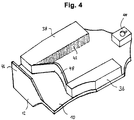
- the Base plate 10 integrally formed a support bracket 36, which for reaching behind by the fingers Grasping the device.
- a housing 38 is provided for the roller guide 18, which is preferably one in FIG 3 recognizable removable cover 40 comprises.
- the opposite, inward sides of the support bracket 36 and / or the Housing 38 may include corrugations 42 to increase grip security.
- This suspension device 44 preferably has the same extent perpendicular to the base plate 10 as the support bracket 36 and the housing 38 to to achieve a stable support of the device when it is placed on the floor.
- a support plate on the rear side thereof 46 arranged. This preferably forms together with that in the opposite Direction of the heel support plate 12 a coherent surface by means of which Foot size measuring device can be set up vertically, for example.
- This support plate 46 is used primarily to place the foot size measuring device securely and stably on the floor, if a person stands on the device with their weight, since the main weight is primarily to be transferred downward in the heel region, that is to say in the region of the heel support plate 12 is.
- the support bracket 36, the housing 38 and the suspension device are preferably located 44 and the support plate 46 with their free end faces in the same plane, so that the device can just be hung on the wall or placed on the floor.
- V-shaped retaining strip 48 On the back of the base plate 10 is also between the support bracket 36 and the housing 38 an approximately V-shaped retaining strip 48 is provided, which serves the fingers of the second Hand of the user to give better pressure to hold the measuring device on the child's foot.
- both the stop 14 can then be moved in its direction as well as the side guide slide 26 in its perpendicular direction of movement adjust and bring into contact with a foot to be measured.
- To measure accuracy can be increased with the other hand, enclosing the V-shaped handle 48 the heel area of the foot size measuring device is pressed against the heel from below. The width of the foot can then be measured on the width scale 34 and the length on the scale 24 read off.
- These scales 34 and 24 are preferably scaled in the "WMS" standard.
- the edge contour of the base plate 10 has an irregular shape in the embodiment shown Contour on what is due to that in terms of measuring children's feet an image, for example of a clown, can be attached to it.
- the arcuate inward formation of the plate edge in the area of the support bracket 36 and the matching curvature of the holding support 36 itself serves to apply the thumb, if this does not press against the trough 30.
- the foot size measuring device is particularly easy to use from what is particularly useful when measuring children's feet.
- the device is easy to operate and can be operated with one hand in particular if the second hand is used Hold or to create pressure against the foot is needed.
- the measurement of the foot size should, as far as possible, be done standing so that the full Body weight on the feet. Now if feet are smaller when sitting, for example on the lap of the mother, to be measured, the lack of pressure on the feet of the Child generated by the user of the measuring device.
- Training the back of the device with different handle strips 36, 38, 48 is an individual The device can be held depending on the situation and hand size of the user. The The device can also be gripped with one hand on the holding support 36, the stop 14 and the side guide slide 26 can be moved by actuating the thumb recess 30.
Landscapes
- Life Sciences & Earth Sciences (AREA)
- Health & Medical Sciences (AREA)
- Biophysics (AREA)
- Veterinary Medicine (AREA)
- Surgery (AREA)
- Physics & Mathematics (AREA)
- Pathology (AREA)
- Engineering & Computer Science (AREA)
- Biomedical Technology (AREA)
- Heart & Thoracic Surgery (AREA)
- Medical Informatics (AREA)
- Molecular Biology (AREA)
- Oral & Maxillofacial Surgery (AREA)
- Animal Behavior & Ethology (AREA)
- General Health & Medical Sciences (AREA)
- Public Health (AREA)
- Dentistry (AREA)
- Length Measuring Devices With Unspecified Measuring Means (AREA)
- Paper (AREA)
- Length-Measuring Instruments Using Mechanical Means (AREA)
- Length Measuring Devices By Optical Means (AREA)
- Measurement Of The Respiration, Hearing Ability, Form, And Blood Characteristics Of Living Organisms (AREA)
- Measuring Pulse, Heart Rate, Blood Pressure Or Blood Flow (AREA)
- Push-Button Switches (AREA)
- Diaphragms For Electromechanical Transducers (AREA)
- Finger-Pressure Massage (AREA)
- Cable Accessories (AREA)
- Error Detection And Correction (AREA)
- Ultra Sonic Daignosis Equipment (AREA)
- Filters That Use Time-Delay Elements (AREA)
- A Measuring Device Byusing Mechanical Method (AREA)
- Footwear And Its Accessory, Manufacturing Method And Apparatuses (AREA)
Description
- Figur 1
- eine Seitenansicht des erfindungsgemäßen Fußgrößenmeßgeräts,
- Figur 2
- eine Draufsicht des Gerätes,
- Figur 3
- einen Schnitt entlang der Linie III-III von Figur 2, und
- Figur 4
- eine perspektivische Ansicht der Rückseite des Gerätes.
Claims (10)
- Fußgrößenmeßgerät mit einer Grundplatte (10), einem ersten festen Anschlag (12) sowie einem diesem gegenüberliegenden, verschiebbaren zweiten Anschlag (14), der mit einer Einrichtung (22, 24) zur beige der gemessenen Fußlänge gekoppelt ist, und am verschiebbaren Anschlag (14) ein quer zu dessen Bewegungsrichtung verschiebbarer Seitenführungsschieber (26) angebracht ist, der mit einer Einrichtung (32, 34) zur Anzeige der Fußbreite gekoppelt ist, dadurch gekennzeichnet, daß eine Haltestutze (36) zum Halten des Gerätes mit einer Hand sowie ein Eingriffselement (30) zur gemeinsamen manuellen Betätigung des verschiebbaren Anschlags (14) und des Seitenführungsschiebers (26) mittels der gleichen Hand vorgesehen sind.
- Fußgrößenmeßgerat nach Anspruch 1, dadurch gekennzeichnet, daß das Eingriffselement als Mulde (30) ausgebildet ist
- Fußgrößenmeßgerät nach Anspruch 1 oder 2 dadurch gekennzeichnet, daß der verschiebbare Anschlag (14) mittels einer Kugel- oder Rollenführung (18) an der Grundplatte (10) geführt ist.
- Fußgrößenmeßgerät nach Anspruch 3, dadurch gekennzeichnet, daß der verschiebbare Anschlag (14) im wesentlichen L-förmig ausgebildet ist und eine dem Seitenführungsschieber (26) gegenüberliegende Seitenplatte (16) aufweist.
- Fußgrößenmeßgerät nach einem der vorhergehenden Ansprüche, dadurch gekennzeichnet, daß die Stützschiene (36) zumindest bereichsweise mit einer Riffelung (42) versehen ist.
- Fußgrößenmeßgerät nach Anspruch 3, dadurch gekennzeichnet, daß die Rollenführung (18) für den verschiebbaren Anschlag (14) an der Rückseite der Grundplatte (10) angeordnet und von einem Gehäuse (38) umschlossen ist.
- Fußgrößenmeßgerät nach Anspruch 6, dadurch gekennzeichnet, daß die Stützschiene (36) und das Rollenführungsgehäuse (38) im wesentlichen parallel zueinander an der Rückseite der Grundplatte (10) angeordnet sind und mittels einer etwa unterhalb des festen Anschlags (12) liegenden Halteleiste (48) miteinander verbunden sind.
- Fußgrößenmeßgerät nach Anspruch 7, dadurch gekennzeichnet, daß die Halteleiste (48) etwa V-förmig ist.
- Fußgrößenmeßgerät nach einem der vorhergehenden Ansprüche, dadurch gekennzeichnet, daß es zur Messung von Füßen der Größe 15 bis 30 ausgebildet ist.
- Fußgrößenmeßgerät nach einem der vorhergehenden Ansprüche, dadurch gekennzeichnet, daß die Fußbreite in mindestens drei Bereichen schmal, mittel und weit, angegeben ist.
Applications Claiming Priority (3)
| Application Number | Priority Date | Filing Date | Title |
|---|---|---|---|
| DE29501215U DE29501215U1 (de) | 1995-01-26 | 1995-01-26 | Fußgrößenmeßgerät |
| DE29501215U | 1995-01-26 | ||
| PCT/DE1996/000134 WO1996022713A1 (de) | 1995-01-26 | 1996-01-26 | Fussgrössenmessgerät |
Publications (2)
| Publication Number | Publication Date |
|---|---|
| EP0805634A1 EP0805634A1 (de) | 1997-11-12 |
| EP0805634B1 true EP0805634B1 (de) | 1998-11-18 |
Family
ID=8002996
Family Applications (1)
| Application Number | Title | Priority Date | Filing Date |
|---|---|---|---|
| EP96900874A Expired - Lifetime EP0805634B1 (de) | 1995-01-26 | 1996-01-26 | Fussgrössenmessgerät |
Country Status (10)
| Country | Link |
|---|---|
| EP (1) | EP0805634B1 (de) |
| AT (1) | ATE173383T1 (de) |
| CZ (1) | CZ6141U1 (de) |
| DE (2) | DE29501215U1 (de) |
| FI (1) | FI3005U1 (de) |
| HU (1) | HU1742U (de) |
| NO (1) | NO973449L (de) |
| PL (1) | PL58308Y1 (de) |
| SK (1) | SK1580U (de) |
| WO (1) | WO1996022713A1 (de) |
Families Citing this family (1)
| Publication number | Priority date | Publication date | Assignee | Title |
|---|---|---|---|---|
| CN106723667B (zh) * | 2017-01-17 | 2022-04-22 | 陕西科技大学 | 脚型测量仪及其测量方法 |
Family Cites Families (6)
| Publication number | Priority date | Publication date | Assignee | Title |
|---|---|---|---|---|
| DE7232306U (de) * | 1972-11-30 | Leske H | Fußmeßgerät | |
| DE650833C (de) * | 1936-02-05 | 1937-10-02 | Gust Rafflenbeul Fa | Fussmessvorrichtung |
| DE1942013U (de) * | 1966-03-24 | 1966-07-07 | Salamander A G | Vorrichtung zum messen der fussgroesse. |
| DE2447474B2 (de) * | 1974-10-04 | 1978-05-11 | Winkle Brdr | Fußmeßapparat |
| GB1573495A (en) * | 1978-04-24 | 1980-08-28 | Malthouse Ranger Ltd | Automatic foot gauge |
| GB2115164B (en) * | 1982-02-17 | 1985-06-05 | Marks Spencer Plc | Foot measuring board |
-
1995
- 1995-01-26 DE DE29501215U patent/DE29501215U1/de not_active Expired - Lifetime
-
1996
- 1996-01-26 AT AT96900874T patent/ATE173383T1/de not_active IP Right Cessation
- 1996-01-26 PL PL96106370U patent/PL58308Y1/xx unknown
- 1996-01-26 HU HU19969700030U patent/HU1742U/hu unknown
- 1996-01-26 WO PCT/DE1996/000134 patent/WO1996022713A1/de not_active Ceased
- 1996-01-26 EP EP96900874A patent/EP0805634B1/de not_active Expired - Lifetime
- 1996-01-26 SK SK101-97U patent/SK1580U/sk unknown
- 1996-01-26 CZ CZ19976402U patent/CZ6141U1/cs not_active IP Right Cessation
- 1996-01-26 DE DE59600832T patent/DE59600832D1/de not_active Expired - Fee Related
-
1997
- 1997-02-25 FI FI970098U patent/FI3005U1/fi active
- 1997-07-25 NO NO973449A patent/NO973449L/no unknown
Also Published As
| Publication number | Publication date |
|---|---|
| ATE173383T1 (de) | 1998-12-15 |
| FI3005U1 (fi) | 1997-08-13 |
| WO1996022713A1 (de) | 1996-08-01 |
| EP0805634A1 (de) | 1997-11-12 |
| NO973449L (no) | 1997-09-25 |
| PL58308Y1 (en) | 2000-12-29 |
| NO973449D0 (no) | 1997-07-25 |
| DE59600832D1 (de) | 1998-12-24 |
| SK1580U (sk) | 1997-08-06 |
| PL106370U1 (en) | 1997-08-04 |
| HU9700030V0 (en) | 1997-03-28 |
| FIU970098U0 (fi) | 1997-02-25 |
| DE29501215U1 (de) | 1995-03-23 |
| CZ6141U1 (cs) | 1997-06-16 |
| HU1742U (en) | 2000-04-28 |
Similar Documents
| Publication | Publication Date | Title |
|---|---|---|
| DE2145884C3 (de) | Fußgymnastik-Vorrichtung für bettlägerige Patienten | |
| DE1920766A1 (de) | Geraet zur Vermessung des menschlichen Koerpers | |
| DE2855649A1 (de) | Verfahren und vorrichtung zum schneiden von fliesen | |
| EP0805634B1 (de) | Fussgrössenmessgerät | |
| DE1548305C3 (de) | Gerät zur Bestimmung der Oberflächenrauhigkeit | |
| DE2307879A1 (de) | Personenwaage | |
| DE2447474C3 (de) | ||
| AT511462A4 (de) | Messvorrichtung für biegewerkstücke | |
| DE69801128T2 (de) | Vorderbacken einer Sicherheitsskibindung | |
| DE19833568A1 (de) | 3D-Wirbelsäulenmeßgerät | |
| DE458882C (de) | Vorrichtung zum Messen von Fuessen | |
| DE288221C (de) | ||
| DE3335743A1 (de) | Vorrichtung zur ausmessung leicht deformierbarer objekte | |
| DE1549157B1 (de) | Vorrichtung zum einstellen des grundpreises an einer waage mit nachlaufeinrichtung | |
| DE3632751C1 (de) | Laengenmesstaster mit einem schwenkbar gelagerten Tastarm | |
| DE2522419A1 (de) | Zentriervorrichtung | |
| DE936475C (de) | Messinstrument | |
| DE485899C (de) | Handdruckmaschine mit einer gegen die Druckwalze auswechselbaren Messerscheibe zum Schneiden von Papier u. dgl. | |
| DE29500810U1 (de) | Schuhinnenlängen-Meßschieber | |
| DE2660055C2 (de) | Vorrichtung zum Überprüfen des Auslösemechanismus einer Skibindung bei angeschnalltem Ski | |
| DE20215090U1 (de) | Schuhlehre | |
| DE450593C (de) | Vorrichtung zur schnellen Bestimmung der fuer Knickfuesse jeweils passendsten Stiefeleinlagen | |
| DE380676C (de) | Vorrichtung zum Messen von Fuessen oder Leisten | |
| DE8716705U1 (de) | Vorrichtung zur Prüfung der Härte eines Tennisballs | |
| DE630375C (de) | Fussmessgeraet |
Legal Events
| Date | Code | Title | Description |
|---|---|---|---|
| PUAI | Public reference made under article 153(3) epc to a published international application that has entered the european phase |
Free format text: ORIGINAL CODE: 0009012 |
|
| 17P | Request for examination filed |
Effective date: 19970312 |
|
| AK | Designated contracting states |
Kind code of ref document: A1 Designated state(s): AT BE CH DE DK ES FR GB GR IE IT LI LU NL PT SE |
|
| GRAG | Despatch of communication of intention to grant |
Free format text: ORIGINAL CODE: EPIDOS AGRA |
|
| GRAG | Despatch of communication of intention to grant |
Free format text: ORIGINAL CODE: EPIDOS AGRA |
|
| GRAH | Despatch of communication of intention to grant a patent |
Free format text: ORIGINAL CODE: EPIDOS IGRA |
|
| 17Q | First examination report despatched |
Effective date: 19980226 |
|
| GRAH | Despatch of communication of intention to grant a patent |
Free format text: ORIGINAL CODE: EPIDOS IGRA |
|
| GRAA | (expected) grant |
Free format text: ORIGINAL CODE: 0009210 |
|
| AK | Designated contracting states |
Kind code of ref document: B1 Designated state(s): AT BE CH DE DK ES FR GB GR IE IT LI LU NL PT SE |
|
| PG25 | Lapsed in a contracting state [announced via postgrant information from national office to epo] |
Ref country code: SE Free format text: THE PATENT HAS BEEN ANNULLED BY A DECISION OF A NATIONAL AUTHORITY Effective date: 19981118 Ref country code: NL Free format text: LAPSE BECAUSE OF FAILURE TO SUBMIT A TRANSLATION OF THE DESCRIPTION OR TO PAY THE FEE WITHIN THE PRESCRIBED TIME-LIMIT Effective date: 19981118 Ref country code: IT Free format text: LAPSE BECAUSE OF FAILURE TO SUBMIT A TRANSLATION OF THE DESCRIPTION OR TO PAY THE FEE WITHIN THE PRE;WARNING: LAPSES OF ITALIAN PATENTS WITH EFFECTIVE DATE BEFORE 2007 MAY HAVE OCCURRED AT ANY TIME BEFORE 2007. THE CORRECT EFFECTIVE DATE MAY BE DIFFERENT FROM THE ONE RECORDED.SCRIBED TIME-LIMIT Effective date: 19981118 Ref country code: GR Free format text: LAPSE BECAUSE OF NON-PAYMENT OF DUE FEES Effective date: 19981118 Ref country code: ES Free format text: THE PATENT HAS BEEN ANNULLED BY A DECISION OF A NATIONAL AUTHORITY Effective date: 19981118 |
|
| REF | Corresponds to: |
Ref document number: 173383 Country of ref document: AT Date of ref document: 19981215 Kind code of ref document: T |
|
| REG | Reference to a national code |
Ref country code: CH Ref legal event code: NV Representative=s name: R. A. EGLI & CO. PATENTANWAELTE Ref country code: CH Ref legal event code: EP |
|
| GBT | Gb: translation of ep patent filed (gb section 77(6)(a)/1977) |
Effective date: 19981119 |
|
| REF | Corresponds to: |
Ref document number: 59600832 Country of ref document: DE Date of ref document: 19981224 |
|
| REG | Reference to a national code |
Ref country code: IE Ref legal event code: FG4D Free format text: GERMAN |
|
| ET | Fr: translation filed | ||
| PG25 | Lapsed in a contracting state [announced via postgrant information from national office to epo] |
Ref country code: LU Free format text: LAPSE BECAUSE OF NON-PAYMENT OF DUE FEES Effective date: 19990126 |
|
| PG25 | Lapsed in a contracting state [announced via postgrant information from national office to epo] |
Ref country code: PT Free format text: LAPSE BECAUSE OF FAILURE TO SUBMIT A TRANSLATION OF THE DESCRIPTION OR TO PAY THE FEE WITHIN THE PRESCRIBED TIME-LIMIT Effective date: 19990218 Ref country code: DK Free format text: LAPSE BECAUSE OF FAILURE TO SUBMIT A TRANSLATION OF THE DESCRIPTION OR TO PAY THE FEE WITHIN THE PRESCRIBED TIME-LIMIT Effective date: 19990218 |
|
| NLV1 | Nl: lapsed or annulled due to failure to fulfill the requirements of art. 29p and 29m of the patents act | ||
| PLBE | No opposition filed within time limit |
Free format text: ORIGINAL CODE: 0009261 |
|
| STAA | Information on the status of an ep patent application or granted ep patent |
Free format text: STATUS: NO OPPOSITION FILED WITHIN TIME LIMIT |
|
| REG | Reference to a national code |
Ref country code: IE Ref legal event code: FD4D |
|
| 26N | No opposition filed | ||
| REG | Reference to a national code |
Ref country code: GB Ref legal event code: IF02 |
|
| PGFP | Annual fee paid to national office [announced via postgrant information from national office to epo] |
Ref country code: GB Payment date: 20021029 Year of fee payment: 8 |
|
| PGFP | Annual fee paid to national office [announced via postgrant information from national office to epo] |
Ref country code: BE Payment date: 20021105 Year of fee payment: 8 |
|
| PGFP | Annual fee paid to national office [announced via postgrant information from national office to epo] |
Ref country code: CH Payment date: 20021211 Year of fee payment: 8 |
|
| PGFP | Annual fee paid to national office [announced via postgrant information from national office to epo] |
Ref country code: AT Payment date: 20030127 Year of fee payment: 8 |
|
| PGFP | Annual fee paid to national office [announced via postgrant information from national office to epo] |
Ref country code: FR Payment date: 20030129 Year of fee payment: 8 |
|
| PGFP | Annual fee paid to national office [announced via postgrant information from national office to epo] |
Ref country code: DE Payment date: 20030326 Year of fee payment: 8 |
|
| PG25 | Lapsed in a contracting state [announced via postgrant information from national office to epo] |
Ref country code: GB Free format text: LAPSE BECAUSE OF NON-PAYMENT OF DUE FEES Effective date: 20040126 Ref country code: AT Free format text: LAPSE BECAUSE OF NON-PAYMENT OF DUE FEES Effective date: 20040126 |
|
| PG25 | Lapsed in a contracting state [announced via postgrant information from national office to epo] |
Ref country code: LI Free format text: LAPSE BECAUSE OF NON-PAYMENT OF DUE FEES Effective date: 20040131 Ref country code: CH Free format text: LAPSE BECAUSE OF NON-PAYMENT OF DUE FEES Effective date: 20040131 Ref country code: BE Free format text: LAPSE BECAUSE OF NON-PAYMENT OF DUE FEES Effective date: 20040131 |
|
| BERE | Be: lapsed |
Owner name: *HAUPTVERBAND DER DEUTSCHEN SCHUHINDUSTRIE E.V. Effective date: 20040131 |
|
| PG25 | Lapsed in a contracting state [announced via postgrant information from national office to epo] |
Ref country code: DE Free format text: LAPSE BECAUSE OF NON-PAYMENT OF DUE FEES Effective date: 20040803 |
|
| GBPC | Gb: european patent ceased through non-payment of renewal fee |
Effective date: 20040126 |
|
| REG | Reference to a national code |
Ref country code: CH Ref legal event code: PL |
|
| PG25 | Lapsed in a contracting state [announced via postgrant information from national office to epo] |
Ref country code: FR Free format text: LAPSE BECAUSE OF NON-PAYMENT OF DUE FEES Effective date: 20040930 |
|
| REG | Reference to a national code |
Ref country code: FR Ref legal event code: ST |