EP0805088A1 - Vorrichtung zur Befestigung einer Kabine einer Seilbahnanlage an einem Gehänge - Google Patents
Vorrichtung zur Befestigung einer Kabine einer Seilbahnanlage an einem Gehänge Download PDFInfo
- Publication number
- EP0805088A1 EP0805088A1 EP96890079A EP96890079A EP0805088A1 EP 0805088 A1 EP0805088 A1 EP 0805088A1 EP 96890079 A EP96890079 A EP 96890079A EP 96890079 A EP96890079 A EP 96890079A EP 0805088 A1 EP0805088 A1 EP 0805088A1
- Authority
- EP
- European Patent Office
- Prior art keywords
- support
- cabin
- roof
- support device
- cabin roof
- Prior art date
- Legal status (The legal status is an assumption and is not a legal conclusion. Google has not performed a legal analysis and makes no representation as to the accuracy of the status listed.)
- Granted
Links
- 239000000725 suspension Substances 0.000 title 1
- 238000013016 damping Methods 0.000 claims abstract description 20
- 230000002787 reinforcement Effects 0.000 claims description 3
- XLYOFNOQVPJJNP-UHFFFAOYSA-N water Substances O XLYOFNOQVPJJNP-UHFFFAOYSA-N 0.000 claims description 3
- 230000003014 reinforcing effect Effects 0.000 claims 1
- 108010066057 cabin-1 Proteins 0.000 description 10
- 238000010276 construction Methods 0.000 description 2
- 230000001771 impaired effect Effects 0.000 description 1
- 238000005096 rolling process Methods 0.000 description 1
Images


Classifications
-
- B—PERFORMING OPERATIONS; TRANSPORTING
- B61—RAILWAYS
- B61B—RAILWAY SYSTEMS; EQUIPMENT THEREFOR NOT OTHERWISE PROVIDED FOR
- B61B12/00—Component parts, details or accessories not provided for in groups B61B7/00 - B61B11/00
- B61B12/02—Suspension of the load; Guiding means, e.g. wheels; Attaching traction cables
- B61B12/028—Cabin or seat suspension means
-
- B—PERFORMING OPERATIONS; TRANSPORTING
- B61—RAILWAYS
- B61B—RAILWAY SYSTEMS; EQUIPMENT THEREFOR NOT OTHERWISE PROVIDED FOR
- B61B12/00—Component parts, details or accessories not provided for in groups B61B7/00 - B61B11/00
- B61B12/04—Devices for damping vibrations
Definitions
- the present invention relates to a device for fastening a cabin of a cable car system to a hanger, which is formed at its lower end with a support device to which the cabin is attached, wherein damping elements, in particular air springs or gas springs, are provided between the support device and the cabin .
- a support frame is arranged on the roof of the cable car cabin, which is formed with spaced from the roof of the cable car cabin upper support surfaces for damping elements and which is arranged at the lower end of the hanger for the cable car cabin, which with is formed lower support surfaces for damping elements, is undercut.
- Damping elements are provided between the support frame and the support device, which are formed by blocks made of rubber or plastic or by air or gas springs.
- the hanger is formed at the upper end with a clamping device and with trolleys.
- the cable car cabin is articulated to the support frame by means of approximately vertically aligned tabs.
- damping elements are arranged between the support frame and the support device. Since the damping elements are located outside the cabin, there is a risk that they will be damaged by UV rays or that they will be exposed to climatic influences. In particular, icing can also occur.
- the object of the invention is therefore to provide a device for fastening a cabin of a cable car system to a hanger, which has a simpler construction and in which the damping elements are protected against harmful influences.
- This is achieved according to the invention in that at least one support pin protrudes from the support device, which The roof of the car is penetrated in a recess in a manner known per se and a support is provided at the lower free end thereof, the at least one damping element being supported on the one hand on the support and on the other hand on the inside of the car roof. Since the inside of the cabin roof is used here as one of the support surfaces for the damping element, a substantial simplification is achieved in the attachment of the cabin.
- the damping element is located below the cabin roof and thus inside the cabin, which means that its functionality cannot be impaired by UV rays or climatic influences.
- two support bolts protrude downward from the support device, which pass through the cabin roof and at whose lower ends a connecting element is fastened, on which the at least one damping element is supported.
- the clear cross-section of the recesses in the cabin roof significantly exceeds the cross-section of the support bolts, preferably being approximately twice the size, the required lateral mobility of the cable car cabin relative to the support device is ensured.
- these are preferably covered by a cover or the like. surround.
- a buffer element is provided between the outside of the cabin roof and the carrying device.
- the roof is preferably formed with a reinforcement in the areas of attachment to the support device, which reinforcement is e.g. is frame-shaped.
- the cabin roof can be formed in the areas of attachment to the support device with upwardly protruding bulges, within which the at least one support bolt, the connecting element and the at least one damping element are located.
- the support bolts are preferably detachably attached to the support device.
- a cable car cabin 1 is shown, which is attached to the underside of two support devices 2 by means of a device 3 each.
- clamping devices 4 At the upper end of the carrying device 2 there are clamping devices 4, by means of which the cabin 1 can be clamped to two carrying and conveying ropes.
- rolling devices 5 are provided, by means of which the car 1 in the stations, after it has been uncoupled from the carrying and conveying rope, along rails to the entry and exit areas, in which they were climbed on and off by the passengers can be moved.
- the support devices 2 are formed with approximately horizontally protruding support rails 21 which are provided with two bores 22 in the region of their free ends.
- the fastening device 3 consists in that each of these bores 22 is penetrated by a carrying bolt 31, which extends through recesses 12 provided in the roof 11 of the cable car cabin 1 and which are formed at their free lower ends with a connecting element 32.
- This connecting element 32 and the opposite region 13 of the cabin roof form the support surfaces for at least one damping element 33.
- a buffer element 34 protrudes from the outside of the cabin roof 11.
- the areas of the roof 11 of the cable car cabin 1, in which the fastening devices 3 are located, are provided with bulges 10 pointing upwards.
- the cable car cabin 1 is designed with the same clear height over its entire space. To the required strength of this To ensure areas of the roof 11 of the cable car cabin 1, the bulges 10 are surrounded by stiffening frames 15.
- Fig. 3a the fastening device is shown in the position in which the cable car cabin 1 is unloaded.
- the fastening device 3 is shown in FIG. 3b in the position in which there are 1 passengers in the cable car cabin.
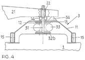
- FIG. 4 shows an embodiment in which only a single support pin 31 projects downward from the support rail 21, to the lower end of which a disk 32a is attached, which forms the lower support for the ring-shaped damping element 33.
- the roof 11 of the cable car cabin 1 forms one of the contact surfaces of the damping elements 33 and 33 a provided between the support device 2 and the cable car cabin 1, this considerably simplifies the construction.
- the damping elements 33 and 33a are thereby protected against UV rays and against climatic influences.
- 12 shielding plates 14 are provided above these recesses. Bellows can also be provided in their place.
- the support bolts 31 are detachably fastened to the support rails 21.
Landscapes
- Engineering & Computer Science (AREA)
- Transportation (AREA)
- Mechanical Engineering (AREA)
- Body Structure For Vehicles (AREA)
- Chain Conveyers (AREA)
- Fittings On The Vehicle Exterior For Carrying Loads, And Devices For Holding Or Mounting Articles (AREA)
- Automobile Manufacture Line, Endless Track Vehicle, Trailer (AREA)
Abstract
Description
- Die gegenständliche Erfindung betrifft eine Vorrichtung zur Befestigung einer Kabine einer Seilbahnanlage an einem Gehänge, welches an seinem unteren Ende mit einer Trageinrichtung ausgebildet ist, an welcher die Kabine befestigt ist, wobei zwischen der Trageinrichtung und der Kabine Dämpfungselemente, insbesondere Luftfedern oder Gasfedern, vorgesehen sind.
- Bei einer derartigen Vorrichtung, welche z.B. aus der WO 93/09013 bekannt ist, ist am Dach der Seilbahnkabine ein Traggestell angeordnet, welches mit im Abstand vom Dach der Seilbahnkabine befindlichen oberen Auflageflächen für Dämpfungselemente ausgebildet ist und welches von einer am unteren Ende des Gehänges für die Seilbahnkabine angeordneten Trageinrichtung, welche mit unteren Auflageflächen für Dämpfungselemente ausgebildet ist, untergriffen ist. Dabei sind zwischen dem Traggestell und der Trageinrichtung Dämpfungselemente vorgesehen, welche durch Klötze aus Gummi oder Kunststoff oder durch Luft- bzw. Gasfedern gebildet sind. Das Gehänge ist am oberen Ende mit einer Klemmeinrichtung und mit Rollapparaten ausgebildet. Die Seilbahnkabine ist am Traggestell mittels angenähert vertikal ausgerichteter Laschen gelenkig befestigt.
- Da bei dieser bekannten Vorrichtung eine an der Unterseite des Gehänges angeordnete Trageinrichtung vorgesehen ist, welche das Traggestell untergreift, wird ein großer konstruktiver Aufwand bedingt. Weiters sind zwischen dem Traggestell und der Trageinrichtung Dämpfungselemente angeordnet. Da sich die Dämpfungselemente außerhalb der Kabine befinden, besteht die Gefahr, daß diese durch UV-Strahlen geschädigt werden bzw. daß diese klimatischen Einflüssen ausgesetzt sind. Insbesondere können auch Vereisungen auftreten.
- Der gegenständlichen Erfindung liegt demnach die Aufgabe zugrunde, eine Vorrichtung zur Befestigung einer Kabine einer Seilbahnanlage an einem Gehänge zu schaffen, welche einen einfacheren Aufbau aufweist und bei welcher die Dämpfungselemente gegenüber schädlichen Einflüssen geschützt sind. Dies wird erfindungsgemäß dadurch erzielt, daß von der Trageinrichtung mindestens ein Tragbolzen abragt, welcher das Kabinendach in an sich bekannter Weise in einer Ausnehmung durchsetzt und an dessen unterem freien Ende ein Auflager vorgesehen ist, wobei sich das mindestens eine Dämpfungselement einerseits am Auflager und andererseits an der Innenseite des Kabinendaches abstützt. Da hierbei die Innenseite des Kabinendaches als eine der Auflageflächen für das Dämpfungselement verwendet ist, wird eine wesentliche Vereinfachung in der Befestigung der Kabine erzielt. Zudem befindet sich das Dämpfungselement unterhalb des Kabinendaches und damit innerhalb der Kabine, wodurch es weder durch UV-Strahlen noch durch klimatische Einflüsse in seiner Funktionsfähigkeit beeinträchtigt werden kann.
- Vorzugsweise ragen von der Trageinrichtung zwei Tragbolzen nach unten ab, welche das Kabinendach durchsetzen und an deren unteren Enden ein Verbindungselement befestigt ist, an welchem sich das mindestens eine Dämpfungselement abstützt. Da weiters der lichte Querschnitt der Ausnehmungen im Kabinendach den Querschnitt der Tragbolzen maßgeblich überschreitet, wobei er vorzugsweise etwa die doppelte Größe aufweist, ist die erforderliche seitliche Beweglichkeit der Seilbahnkabine gegenüber der Trageinrichtung gewährleistet. Um dabei einen Durchtritt von Wasser durch die Ausnehmungen zu verhindern, sind diese vorzugsweise von einer Abdeckung od.dgl. umgeben.
- Nach weiteren bevorzugten Merkmalen ist zwischen der Außenseite des Kabinendaches und der Trageinrichtung ein Pufferelement vorgesehen. Weiters ist vorzugsweise das Dach in den Bereichen der Befestigung an der Trageinrichtung mit einer Verstärkung ausgebildet, welche z.B. rahmenförmig ausgebildet ist. Zudem kann das Kabinendach in den Bereichen der Befestigung an der Trageinrichtung mit nach oben abragenden Auswölbungen ausgebildet sein, innerhalb welcher sich der mindestens eine Tragbolzen, das Verbindungselement und das mindestens eine Dämpfungselement befinden. Um schließlich die Seilbahnkabine von der Trageinrichtung in einfacher Weise entfernen zu können, sind vorzugsweise die Tragbolzen an der Trageinrichtung lösbar befestigt.
- Der Gegenstand der Erfindung ist nachstehend anhand eines in der Zeichnung dargestellten Ausführungsbeispiels näher erläutert. Es zeigen:
- Fig. 1
- eine Seilbahnkabine mit einer erfindungsgemäßen Befestigungsvorrichtung, in Seitenansicht und teilweise geschnitten,
- Fig. 2
- die Seilbahnkabine mit einer erfindungsgemäßen Befestigungsvorrichtung, in Vorderansicht,
- die Fig. 3a und 3b
- die erfindungsgemäße Befestigungsvorrichtung, in zwei unterschiedlichen Lagen der Belastung und
- Fig. 4
- eine weitere Ausführungsform der Befestigung, in Seitenansicht und teilweise geschnitten.
- In den Fig. 1 und 2 ist eine Seilbahnkabine 1 dargestellt, welche an der Unterseite von zwei Trageinrichtungen 2 mittels jeweils einer Vorrichtung 3 befestigt ist. Am oberen Ende der Trageinrichtung 2 befinden sich Klemmvorrichtungen 4, mittels welcher die Kabine 1 an zwei Trag- und Förderseile anklemmbar ist. Weiters sind am oberen Ende der Trageinrichtungen Rollapparate 5 vorgesehen, mittels welcher die Kabine 1 in den Stationen, nachdem sie vom Trag- und Förderseil abgekuppelt wurde, längs Schienen zu den Einstiegs- bzw. Ausstiegsbereichen, in welchen sie von den Passagieren bestiegen bzw. verlassen werden kann, verfahrbar ist.
- Wie dies aus Fig. 3a ersichtlich ist, sind die Trageinrichtungen 2 mit angenähert horizontal ausragenden Tragschienen 21 ausgebildet, welche im Bereich ihrer freien Enden mit zwei Bohrungen 22 versehen sind. Die Befestigungsvorrichtung 3 besteht darin, daß diese Bohrungen 22 von jeweils einem Tragbolzen 31 durchsetzt sind, welche im Dach 11 der Seilbahnkabine 1 vorgesehene Ausnehmungen 12 durchragen und welche an ihren freien unteren Enden mit einem Verbindungselement 32 ausgebildet sind. Dieses Verbindungselement 32 und der gegenüberliegende Bereich 13 des Kabinendaches bilden die Auflageflächen für mindestens ein Dämpfungselement 33. Zudem ragt an der Außenseite des Kabinendaches 11 ein Pufferelement 34 ab. Die Bereiche des Daches 11 der Seilbahnkabine 1, in welchen sich die Befestigungsvorrichtungen 3 befinden, sind mit nach oben gerichteten Auswölbungen 10 versehen. Hierdurch ist die Seilbahnkabine 1 über ihren gesamten Raum mit einer gleichen lichten Höhe ausgebildet. Um die erforderliche Festigkeit dieser Bereiche des Daches 11 der Seilbahnkabine 1 zu gewährleisten, sind die Auswölbungen 10 von Versteifungsrahmen 15 umgeben.
- In Fig. 3a ist die Befestigungsvorrichtung in derjenigen Lage dargestellt, in welcher die Seilbahnkabine 1 unbelastet ist. Demgegenüber ist in Fig. 3b die Befestigungsvorrichtung 3 in derjenigen Lage dargestellt, in welcher sich in der Seilbahnkabine 1 Passagiere befinden.
- In Fig. 4 ist eine Ausführungsform dargestellt, in welcher von der Tragschiene 21 nur ein einziger Tragbolzen 31 nach unten abragt, an dessen unterem Ende eine Scheibe 32a befestigt ist, welche das untere Auflager für das ringförmig ausgebildete Dämpfungselement 33 bildet.
- Da das Dach 11 der Seilbahnkabine 1 eine der Auflageflächen der zwischen der Trageinrichtung 2 und der Seilbahnkabine 1 vorgesehenen Dämpfungselemente 33 bzw. 33a bildet, wird hierdurch eine wesentliche Vereinfachung in der Konstruktion erzielt. Zudem sind hierdurch die Dämpfungselemente 33 bzw. 33a gegenüber UV-Strahlen bzw. gegenüber klimatischen Einflüssen geschützt. Um einen Durchtritt von Wasser durch die Ausnehmungen 12 hindurch zu verhindern, sind oberhalb dieser Ausnehmungen 12 Abschirmbleche 14 vorgesehen. An deren Stelle können auch Faltenbälge vorgesehen sein.
Um weiters die Seilbahnkabine 1 von der Trageinrichtung 2 in einfacher Weise entfernen zu können, sind die Tragbolzen 31 an den Tragschienen 21 lösbar befestigt.
Claims (9)
- Vorrichtung zur Befestigung einer Kabine einer Seilbahnanlage an einem Gehänge, welches an seinem unteren Ende mit einer Trageinrichtung ausgebildet ist, an welcher die Kabine befestigt ist, wobei zwischen der Trageinrichtung und der Kabine Dämpfungselemente, insbesondere Luftfedern oder Gasfedern, vorgesehen sind, dadurch gekennzeichnet, daß von der Trageinrichtung [3] mindestens ein Tragbolzen [31] abragt, welcher in an sich bekannter Weise das Kabinendach [11] in einer Ausnehmung [12] durchsetzt und an dessen unterem freien Ende ein Auflager [32, 32a] befestigt ist, wobei sich das mindestens eine Dämpfungselement [33] am Auflager [32, 32a] und an der Innenseite des Kabinendaches [11] abstützt.
- Vorrichtung nach Patentanspruch 1, dadurch gekennzeichnet, daß von den freien Enden der Trageinrichtung [2] zwei Tragbolzen [31] nach unten abragen, welche das Kabinendach [11] durchsetzen und an deren unteren Enden ein Verbindungselement [32] befestigt ist, an welchem sich das mindesens eine Dämpfungselement [33] abstützt.
- Vorrichtung nach einem der Patentansprüche 1 und 2, dadurch gekennzeichnet, daß der lichte Querschnitt der Ausnehmungen [12] den Querschnitt der Tragbolzen [31] maßgeblich überschreitet, wobei er vorzugsweise etwa doppelte Größe aufweist.
- Vorrichtung nach einem der Patentansprüche 1 bis 3, dadurch gekennzeichnet, daß die Ausnehmungen [12] von einer Abdeckung [14] od.dgl. umgeben sind, durch welche ein Durchtritt von Wasser verhindert wird.
- Vorrichtung nach einem der Patentansprüche 1 bis 4, dadurch gekennzeichnet, daß zwischen der Außenseite des Kabinendaches [11] und der Trageinrichtung [2] ein Pufferelement [34] vorgesehen ist.
- Vorrichtung nach einem der Patentansprüche 1 bis 5, dadurch gekennzeichnet, daß das Kabinendach [11] in den Bereichen der Befestigung an der Trageinrichtung [2] mit einer Verstärkung [15] ausgebildet ist.
- Vorrichtung nach Patentanspruch 6, dadurch gekennzeichnet, daß das Kabinendach [11] in den Bereichen der Befestigung an der Trageinrichtung [2] mit rahmenförmigen Verstärkungsschienen [15] ausgebildet ist.
- Vorrichtung nach einem der Patentansprüche 1 bis 7, dadurch gekennzeichnet, daß das Kabinendach [11] in den Bereichen der Befestigung an der Trageinrichtung [2] mit nach oben abragenden Auswölbungen [10] ausgebildet ist.
- Vorrichtung nach einem der Patentansprüche 1 bis 8, dadurch gekennzeichnet, daß die Tragbolzen [31] an der Trageinrichtung [2] lösbar befestigt sind.
Priority Applications (5)
| Application Number | Priority Date | Filing Date | Title |
|---|---|---|---|
| ES96890079T ES2159713T3 (es) | 1996-05-03 | 1996-05-03 | Procedimiento para la fijacion de la cabina de un teleferico a un dispositivo de suspension. |
| DE59607500T DE59607500D1 (de) | 1996-05-03 | 1996-05-03 | Vorrichtung zur Befestigung einer Kabine einer Seilbahnanlage an einem Gehänge |
| EP96890079A EP0805088B1 (de) | 1996-05-03 | 1996-05-03 | Vorrichtung zur Befestigung einer Kabine einer Seilbahnanlage an einem Gehänge |
| AT96890079T ATE204238T1 (de) | 1996-05-03 | 1996-05-03 | Vorrichtung zur befestigung einer kabine einer seilbahnanlage an einem gehänge |
| EP00113989A EP1034995B1 (de) | 1996-05-03 | 1996-05-03 | Kabine für eine Seilbahnanlage |
Applications Claiming Priority (1)
| Application Number | Priority Date | Filing Date | Title |
|---|---|---|---|
| EP96890079A EP0805088B1 (de) | 1996-05-03 | 1996-05-03 | Vorrichtung zur Befestigung einer Kabine einer Seilbahnanlage an einem Gehänge |
Related Child Applications (1)
| Application Number | Title | Priority Date | Filing Date |
|---|---|---|---|
| EP00113989A Division EP1034995B1 (de) | 1996-05-03 | 1996-05-03 | Kabine für eine Seilbahnanlage |
Publications (2)
| Publication Number | Publication Date |
|---|---|
| EP0805088A1 true EP0805088A1 (de) | 1997-11-05 |
| EP0805088B1 EP0805088B1 (de) | 2001-08-16 |
Family
ID=8226199
Family Applications (2)
| Application Number | Title | Priority Date | Filing Date |
|---|---|---|---|
| EP96890079A Expired - Lifetime EP0805088B1 (de) | 1996-05-03 | 1996-05-03 | Vorrichtung zur Befestigung einer Kabine einer Seilbahnanlage an einem Gehänge |
| EP00113989A Expired - Lifetime EP1034995B1 (de) | 1996-05-03 | 1996-05-03 | Kabine für eine Seilbahnanlage |
Family Applications After (1)
| Application Number | Title | Priority Date | Filing Date |
|---|---|---|---|
| EP00113989A Expired - Lifetime EP1034995B1 (de) | 1996-05-03 | 1996-05-03 | Kabine für eine Seilbahnanlage |
Country Status (4)
| Country | Link |
|---|---|
| EP (2) | EP0805088B1 (de) |
| AT (1) | ATE204238T1 (de) |
| DE (1) | DE59607500D1 (de) |
| ES (1) | ES2159713T3 (de) |
Citations (3)
| Publication number | Priority date | Publication date | Assignee | Title |
|---|---|---|---|---|
| CH518821A (de) * | 1970-09-14 | 1972-02-15 | Frech Anton | Kabine für eine Hoch- oder Luftseilbahn |
| US4338863A (en) * | 1980-04-29 | 1982-07-13 | Pomagalski S.A. | Pneumatic suspension system for ropeway cars |
| FR2694533A1 (fr) * | 1992-08-05 | 1994-02-11 | Pomagalski Sa | Cabine à siège en caisson rotomoulé d'une installation à câble aérien. |
Family Cites Families (4)
| Publication number | Priority date | Publication date | Assignee | Title |
|---|---|---|---|---|
| FR2569643B1 (fr) * | 1984-08-28 | 1986-09-26 | Montaz Mautino Ets | Procede pour l'engagement et le degagement, dans et hors des cables, des moyens de suspension d'un vehicule d'une installation de transport par cables aeriens comportant deux cables porteurs-tracteurs a brins paralleles et moyens pour sa mise en oeuvre |
| FR2591174B1 (fr) * | 1985-12-11 | 1988-02-26 | Pomagalski Sa | Installation de transport a cables aeriens dont les vehicules sont associes aux cables par au moins deux suspentes |
| AT402187B (de) | 1991-11-05 | 1997-02-25 | Doppelmayr & Sohn | Vorrichtung zur befestigung einer kabine, eines sessels od.dgl. einer seilbahnanlage an einem gehänge |
| DE29519704U1 (de) * | 1995-12-12 | 1996-01-25 | Konrad Doppelmayr & Sohn Maschinenfabrik Ges. M.B.H. & Co. Kg, Wolfurt | Kabine für Seilbahnanlagen |
-
1996
- 1996-05-03 EP EP96890079A patent/EP0805088B1/de not_active Expired - Lifetime
- 1996-05-03 DE DE59607500T patent/DE59607500D1/de not_active Expired - Lifetime
- 1996-05-03 AT AT96890079T patent/ATE204238T1/de active
- 1996-05-03 ES ES96890079T patent/ES2159713T3/es not_active Expired - Lifetime
- 1996-05-03 EP EP00113989A patent/EP1034995B1/de not_active Expired - Lifetime
Patent Citations (3)
| Publication number | Priority date | Publication date | Assignee | Title |
|---|---|---|---|---|
| CH518821A (de) * | 1970-09-14 | 1972-02-15 | Frech Anton | Kabine für eine Hoch- oder Luftseilbahn |
| US4338863A (en) * | 1980-04-29 | 1982-07-13 | Pomagalski S.A. | Pneumatic suspension system for ropeway cars |
| FR2694533A1 (fr) * | 1992-08-05 | 1994-02-11 | Pomagalski Sa | Cabine à siège en caisson rotomoulé d'une installation à câble aérien. |
Also Published As
| Publication number | Publication date |
|---|---|
| EP1034995A1 (de) | 2000-09-13 |
| EP1034995B1 (de) | 2001-12-05 |
| EP0805088B1 (de) | 2001-08-16 |
| DE59607500D1 (de) | 2001-09-20 |
| ES2159713T3 (es) | 2001-10-16 |
| ATE204238T1 (de) | 2001-09-15 |
Similar Documents
| Publication | Publication Date | Title |
|---|---|---|
| DE102014104920B4 (de) | Karosseriestruktur mit Dach-Reling | |
| EP0681956B1 (de) | Passagierflugzeug | |
| EP2853460A1 (de) | Seilbahnanlage zur Beförderung von Personen bzw. Gütern | |
| EP0094628B1 (de) | Schiebetor | |
| EP1238880B1 (de) | Anlage zum Abfahren von Personen von einer Bergstation in eine Talstation | |
| AT404817B (de) | Vorrichtung zur befestigung einer kabine einer seilbahnanlage an einem gehänge | |
| EP0805088B1 (de) | Vorrichtung zur Befestigung einer Kabine einer Seilbahnanlage an einem Gehänge | |
| EP0559635B1 (de) | Schienenfahrzeug | |
| EP1174325B1 (de) | Fahrwerk für das Fahrbetriebsmittel einer Seilbahnanlage | |
| AT409952B (de) | Anlage zum abfahren von personen von einer bergstation in eine talstation | |
| EP0254084A1 (de) | Niveaugeregelte, gasgefederte Wagenkastenabstützung für ein Schienenfahrzeug | |
| DE3623032A1 (de) | Verfahreinheit fuer seile und dgl. | |
| EP0239735A2 (de) | Elastische Lagerung von Baugruppen in Fahrzeugen, insbesondere Schienenfahrzeugen | |
| EP1621485A1 (de) | Fördersystem zum Transport von Karosserien | |
| WO2002018735A1 (de) | Türbefestigung | |
| AT8527U1 (de) | Vorrichtung zum transport von gleisabschnitten oder montierten gleisverbindungen | |
| EP0580566B1 (de) | Portalfahrwerk für Schienenfahrzeuge | |
| DE29808253U1 (de) | Vorrichtung zur Befestigung eines elektrischen Zähler- und/oder Verteilerfeldes in einem Schrankgehäuse | |
| DE2758056B2 (de) | Sicherheitsabdeckung für eine Drehkranzabschrankung in einem Gelenkomnibus | |
| EP0215221A1 (de) | Gleiskette | |
| EP1473206B1 (de) | Stirnwand für Eisenbahngüterwagen | |
| DD248551A1 (de) | Einbringung und befestigung von lasten in einem deckenhohlraum eines fahrzeuges, beispielsweise eines schienenfahrzeuges | |
| DE3913653C2 (de) | Spielgerät für Kinderspielplätze, Kindergärten oder dgl. | |
| EP0215181A2 (de) | Fahrwerk für ortsveränderbare Bauteile | |
| DE29806318U1 (de) | Lastwagenaufbau zur Aufnahme von Containern o.dgl. |
Legal Events
| Date | Code | Title | Description |
|---|---|---|---|
| PUAI | Public reference made under article 153(3) epc to a published international application that has entered the european phase |
Free format text: ORIGINAL CODE: 0009012 |
|
| AK | Designated contracting states |
Kind code of ref document: A1 Designated state(s): AT CH DE ES FR IT LI SE |
|
| 17P | Request for examination filed |
Effective date: 19980122 |
|
| 17Q | First examination report despatched |
Effective date: 19990802 |
|
| RAP1 | Party data changed (applicant data changed or rights of an application transferred) |
Owner name: INNOVA PATENT GMBH |
|
| GRAG | Despatch of communication of intention to grant |
Free format text: ORIGINAL CODE: EPIDOS AGRA |
|
| GRAG | Despatch of communication of intention to grant |
Free format text: ORIGINAL CODE: EPIDOS AGRA |
|
| GRAG | Despatch of communication of intention to grant |
Free format text: ORIGINAL CODE: EPIDOS AGRA |
|
| GRAH | Despatch of communication of intention to grant a patent |
Free format text: ORIGINAL CODE: EPIDOS IGRA |
|
| GRAH | Despatch of communication of intention to grant a patent |
Free format text: ORIGINAL CODE: EPIDOS IGRA |
|
| GRAA | (expected) grant |
Free format text: ORIGINAL CODE: 0009210 |
|
| ITF | It: translation for a ep patent filed | ||
| AK | Designated contracting states |
Kind code of ref document: B1 Designated state(s): AT CH DE ES FR IT LI SE |
|
| REF | Corresponds to: |
Ref document number: 204238 Country of ref document: AT Date of ref document: 20010915 Kind code of ref document: T |
|
| REG | Reference to a national code |
Ref country code: CH Ref legal event code: EP |
|
| REG | Reference to a national code |
Ref country code: CH Ref legal event code: NV Representative=s name: LUCHS & PARTNER PATENTANWAELTE |
|
| REF | Corresponds to: |
Ref document number: 59607500 Country of ref document: DE Date of ref document: 20010920 |
|
| REG | Reference to a national code |
Ref country code: ES Ref legal event code: FG2A Ref document number: 2159713 Country of ref document: ES Kind code of ref document: T3 |
|
| ET | Fr: translation filed | ||
| PLBE | No opposition filed within time limit |
Free format text: ORIGINAL CODE: 0009261 |
|
| STAA | Information on the status of an ep patent application or granted ep patent |
Free format text: STATUS: NO OPPOSITION FILED WITHIN TIME LIMIT |
|
| 26N | No opposition filed | ||
| PG25 | Lapsed in a contracting state [announced via postgrant information from national office to epo] |
Ref country code: IT Free format text: LAPSE BECAUSE OF NON-PAYMENT OF DUE FEES Effective date: 20050503 |
|
| PGRI | Patent reinstated in contracting state [announced from national office to epo] |
Ref country code: IT Effective date: 20091201 |
|
| REG | Reference to a national code |
Ref country code: FR Ref legal event code: PLFP Year of fee payment: 20 |
|
| PGFP | Annual fee paid to national office [announced via postgrant information from national office to epo] |
Ref country code: SE Payment date: 20150520 Year of fee payment: 20 Ref country code: CH Payment date: 20150521 Year of fee payment: 20 Ref country code: ES Payment date: 20150527 Year of fee payment: 20 Ref country code: DE Payment date: 20150521 Year of fee payment: 20 |
|
| PGFP | Annual fee paid to national office [announced via postgrant information from national office to epo] |
Ref country code: IT Payment date: 20150514 Year of fee payment: 20 Ref country code: AT Payment date: 20150601 Year of fee payment: 20 Ref country code: FR Payment date: 20150521 Year of fee payment: 20 |
|
| REG | Reference to a national code |
Ref country code: DE Ref legal event code: R071 Ref document number: 59607500 Country of ref document: DE |
|
| REG | Reference to a national code |
Ref country code: CH Ref legal event code: PL |
|
| REG | Reference to a national code |
Ref country code: AT Ref legal event code: MK07 Ref document number: 204238 Country of ref document: AT Kind code of ref document: T Effective date: 20160503 |
|
| REG | Reference to a national code |
Ref country code: ES Ref legal event code: FD2A Effective date: 20160826 |
|
| PG25 | Lapsed in a contracting state [announced via postgrant information from national office to epo] |
Ref country code: ES Free format text: LAPSE BECAUSE OF EXPIRATION OF PROTECTION Effective date: 20160504 |