EP0804637B1 - Verfahren und vorrichtung zum galvanisieren von plattenförmigem behandlungsgut in horizontalen durchlaufanlagen - Google Patents
Verfahren und vorrichtung zum galvanisieren von plattenförmigem behandlungsgut in horizontalen durchlaufanlagen Download PDFInfo
- Publication number
- EP0804637B1 EP0804637B1 EP96902242A EP96902242A EP0804637B1 EP 0804637 B1 EP0804637 B1 EP 0804637B1 EP 96902242 A EP96902242 A EP 96902242A EP 96902242 A EP96902242 A EP 96902242A EP 0804637 B1 EP0804637 B1 EP 0804637B1
- Authority
- EP
- European Patent Office
- Prior art keywords
- treated
- clip
- contacting means
- electroplating
- article
- Prior art date
- Legal status (The legal status is an assumption and is not a legal conclusion. Google has not performed a legal analysis and makes no representation as to the accuracy of the status listed.)
- Expired - Lifetime
Links
Images


Classifications
-
- H—ELECTRICITY
- H05—ELECTRIC TECHNIQUES NOT OTHERWISE PROVIDED FOR
- H05K—PRINTED CIRCUITS; CASINGS OR CONSTRUCTIONAL DETAILS OF ELECTRIC APPARATUS; MANUFACTURE OF ASSEMBLAGES OF ELECTRICAL COMPONENTS
- H05K3/00—Apparatus or processes for manufacturing printed circuits
- H05K3/22—Secondary treatment of printed circuits
- H05K3/24—Reinforcing of the conductive pattern
- H05K3/241—Reinforcing of the conductive pattern characterised by the electroplating method; means therefor, e.g. baths or apparatus
-
- C—CHEMISTRY; METALLURGY
- C25—ELECTROLYTIC OR ELECTROPHORETIC PROCESSES; APPARATUS THEREFOR
- C25D—PROCESSES FOR THE ELECTROLYTIC OR ELECTROPHORETIC PRODUCTION OF COATINGS; ELECTROFORMING; APPARATUS THEREFOR
- C25D17/00—Constructional parts, or assemblies thereof, of cells for electrolytic coating
- C25D17/06—Suspending or supporting devices for articles to be coated
Definitions
- the invention relates to a method and a device for electroplating of plate-shaped items to be treated in horizontal continuous systems, especially for the electrolytic treatment of printed circuit boards and conductor foils.
- each clamp outside the electrolysis cell ie above the bath level, is provided with a brush arrangement for transmitting the electroplating current.
- brackets Due to the cathodic polarity of the bracket, it is within the Electrolysis cell as well as the material to be treated with the one to be deposited Coated metal. To avoid continued The brackets are coated per circulation during the return demetallized again in a demetallization chamber.
- the Demetallization chamber can only for technical reasons contain the electrolyte, which is also in the electrolytic cell.
- the electrolyte is optimized for the metallization, but not for the Demetallization.
- the massive metal job is often done by electrolytic demetallization not completely removed.
- the electrically highly conductive and cathodically polarized brackets as "Predatory cathode" act. The result of this is that the secluded Layer on the circuit board near the brackets is too small. An additional one results from the undesired metal deposition Anode consumption and additional energy consumption, in particular for demetallization.
- the clamps or rods with an electrically insulating Material covered covers at least the area the clamps or rods that protrude into the electrolytic cell. Only the area of actual contact with the material to be treated, e.g. a circuit board, remains without insulation.
- insulation materials come the materials known from galvanotechnical frames like PTFE in question; Glass, ceramics and enamel are also suitable.
- a synchronization the position of the circumferential brackets with the position of the printed circuit boards, that retracted into the system at any time is without disadvantage for a homogeneous layer thickness distribution of the deposited metal not possible.
- the transmission of the cathode potential of the stationary bath current sources abrasive brushes are used on the surrounding clips.
- abrasive brushes are used on the surrounding clips.
- the horizontal electroplating system is parallel to the track the circumferential brackets an elongated rail.
- Each Klammer has a grinding brush, also known as a sliding contact becomes.
- the grinding brush provides the electrical connection from the stationary rail to the circumferential bracket.
- the brackets are used during the return via a second rail. In this In case the brackets get anode potential from another Bath power source. This busbar ends before the second turning point.
- each bracket must be after the reversal point at the end of the infeed section Grasp the clasp. Before the start of the exit reversal point the clamp must release the goods by opening them.
- These closing and opening movements are controlled by stationary inclined planes at the reversal points, over the corresponding Shaped cams of the brackets are forced, forced. This means that the closing and opening of the drive of the rotating Brackets is effected with. The closing force generates itself a spring in the bracket.
- GB-A-22 66 727 describes a system for continuous electroplating disclosed by circuit boards.
- a treatment item is in constant sequence continuously contacted electrically.
- a controlled one Switching the contacting means on and off depending on Treatment gaps are not provided.
- the invention is therefore based on the problem of a method and to provide a device that makes it possible to treat material to be treated in any interrupted sequence by an electrolytic horizontal continuous system so to transport and the described To avoid disadvantages, especially the contacting means not to metallize.
- the endless wrapping brackets will be controlled by the control system at the gripping point so that the bracket with existing PCB at this point in the electro-technical Is switched to the cathode potential with low resistance and grabs the plate at the same time. There is no incoming circuit board at this point, the cathode potential is not going to the the bracket currently located there. At the same time it will Prevents the clip from closing. This state remains during the passage of the clip through the metallization compartment. The process is repeated from bracket to bracket.
- cathode potential now takes the isolated metal in the electrolyte Brackets over the open contacts and over the electrolyte in the galvanotechnical sense a high-resistance potential that below of the cathode potential.
- the turned off Clamp high resistance at a lower anode / cathode voltage lies as a low-impedance brackets.
- Both together causes the brackets switched off compared to the Cathodes and PCBs with low-resistance contact have a slightly anodic effect and do not absorb any galvanizing bath current. Electrolytic metal deposition is thus found Defects in the insulating layer and on the contacts of these clips does not take place during the passage through the metallization compartment.
- the lifting movement is used to raise the bracket against its spring pressure and beyond its grinding position. If the clamp is needed in the clamp gripping point due to an existing item to be treated, the clamp closes when it runs off the inclined plane. At the same time, the bracket goes into its grinding position. If the control system determines that no material to be treated arrives at the clamp gripping point, the clamp should not close and the bracket should not go into the grinding position with its grinding brush. In this case, a lock which can be influenced by the control system ensures that the clamp does not close despite a sliding shoe running off the inclined plane. At the same time, the lock prevents the bracket from reaching the grinding position.
- the force for opening and closing the clamps as well as lifting the bracket against the spring forces is generated by the powerful clamp drive using a sliding block and an inclined plane or by other, sliding, form-fitting connections, such as a link control.
- the controlled lock on the other hand, requires only minimal forces to move it. Therefore, the use of auxiliary energy, such as compressed air, is suitable here.
- the lock consists of a moving part that has two states assumes, namely "clip open and bracket not in grinding position" and "Clamp closed and sanding brush in sanding position". Devices or forces are used to assume these states can be influenced by the control system, d. H. are switchable. For this include electromagnets and compressed air nozzles. Unilaterally on the lock also act on a spring force or gravity. It it is also possible to touch the lock with the help of a switch flag actuate.
- the lock is designed so that it is in the open state the bracket can easily assume the two switching states. At a switching point, the lock blocks the clamp closing movement.
- the two spring-powered clamp parts are supported the lock. No additional energy is required to keep it open.
- the bracket closes unhindered at the other switching point of the lock.
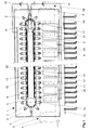
- FIG. 1 shows the electroplating system 1. This is divided into the metallization compartment 2 and in the demetallization compartment 3.
- the incoming plate-shaped items to be treated for example circuit boards, are included the number 4, the outgoing material to be treated is designated 4 '.
- a circulating endless conveyor belt 5, for example a toothed belt, is from the drive wheel and deflection wheel 6 in one direction driven and deflected by the deflection wheel 7 in the other direction.
- On the conveyor belt 5 are at regular intervals of z.
- the Clamps engage after the inlet 9 of the circuit boards 4 in the Electroplating system 1 in the gripping point 10 successively on these plates 4 their edge.
- the inclined planes are located themselves along the transport track. They extend into the diversions 6, 7 into it. In the lower part of Figure 1, the position of the oblique Levels in relation to the gripping point 10 and the opening point 17 shown.
- the inclined level 19 and is in the inlet area in the outlet area 19 '.
- the clamp opens against the closing force the spring clip.
- the clamp is closed again at gripping point 10, regardless of whether a circuit board is at the gripping point 10 or not.
- the bracket 8 through the electroplating system 1 becomes the bracket opened again by running onto the inclined plane 19 '. in the Opening point 17, the circuit board 4 'is released again, if there was a plate in the bracket at all.
- the contact opening point 21 the electrical Potential switched off by the bracket.
- the demetallization compartment 3 passes through the clamps 8 in the example of Figure 1 according to the prior art in a closed Status.
- a deposit cathode act 22 which with the Demetallization power source 16 are electrically connected.
- the problem of such an electroplating system is that described at the beginning Metallize the brackets.
- massive electrolytic Demetallization in the demetallization compartment 3 does not always succeed remove all metallic deposits. That is why also tried to open the brackets through the demetallization compartment to transport the metal deposits to the the PCB-mounting contacts for the field lines more accessible will.
- the open clamp is also over the sanding brush 12 electrically connected to the demetallization current source 16.
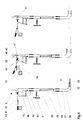
- FIG. 2 shows a horizontal continuous system corresponding to the Figure 1, but with opened and switched off according to the invention Parentheses. As far as parts are identical or have the same effect, corresponding reference numerals of FIG. 1 are used again.
- the circuit boards 4 are successively at the inlet 9 in the electroplating system 1 retracted. In this run-in sequence are between the distances between individual circuit boards. Between everyone Printed circuit board consists of transport engineering and galvanotechnical Establish a normal PCB spacing 22. If missing Circuit board gaps 23 arise.
- the circuit boards 4 have different in practice at least in the direction of transport Lengths and loading of the system take place at any time. This is why the clamp drive is synchronized with the treatment order is not possible.
- Brackets 8 are therefore also between the printed circuit boards 4, that is at the intervals 22 and in positioned the gaps 23.
- the brackets 8 in the areas 22 and 23 remain open and electrically switched off according to the invention.
- the clip opening is shown in the lower part of Figure 2, the Bracket disconnection from the cathode potential is shown in the drawing missing brushes 12 on the relevant brackets shown.
- FIG. 3 shows the components required for switching off the clamps.
- a circuit board sensor 24 in the inlet area of the electroplating system e.g. B. a light barrier, detects the length of each circuit board. At the same time, this means that it has the normal PCB distances 22 and the circuit board gaps 23 detected.
- the motor 25 drives over the gear 26 and the drive wheel 6 on the brackets. This Units are collectively referred to as a clamp drive.
- the motor 25 also drives the transport rollers, not shown, synchronously at the inlet 9 and outlet 18 of the electroplating system.
- the Printed circuit board transport speed essentially depends after the required treatment time of the circuit boards in the Electroplating system. In practice, it is 0.5 to 3 meters per minute. Another sensor measures the current transport speed.
- an incremental displacement sensor 27 It is for example one pulse per millimeter of PCB transport path from. This path constant is in the control system 28 as Stored parameters.
- the control system is one for known programmable logic controller, also commercially available PLC named.
- the current signals from sensors 24 and 27 continuously detects control system 28.
- distance D is stored.
- the distance D is the constant distance of the circuit board edges detected by the circuit board sensor 24 from Gripping point 10 of the brackets.
- the two parameters are used for Calculation of how many pulses from the incremental encoder 27 in the control system 28 must run in until one from the circuit board sensor 24 detected circuit board edge at gripping point 10 has arrived. This applies to both the rising edge, e.g. B.
- the control system 28 controls at the gripping point 10 a lock that is on each bracket. As control energy is used, for example, compressed air 29 by the PLC controlled solenoid valve 30 is switched. The lock gives in free the clamp to close or block it in a switching state they in the other switching state. In the blocked state at the same time placing the grinding brush 12 on the grinding rail 13 prevented.
- FIG. 4 shows an enlarged view of the situation at a normal board distance 22 in top view and the clamp contacts in the side view.
- the distance between two circuit boards 4 varies in practice between about 0 and 30 millimeters.
- the top bracket has the upper clamp contact 31 and the lower part lower clamp contact 32. These grip the circuit board 33.
- Im Hatched area 34 should not close the bracket will. Only when contacts 31 and 32 are fully on the circuit board 4, 33 sit on, they should close.
- the area 34 becomes like this chosen that tolerances do not lead to mistakes.
- the bracket 8 consists of the lower bracket part 36 and the upper clamp part 37.
- a compression spring 38 presses the contacts 31 and 32 of both parts on top of each other. This results in the closing force the bracket.
- the lower clamp part 36 is of a sliding guide 39 out, and it is on the endlessly circulating conveyor belt 5 attached.
- At part 36 there is a bearing 40 for the bracket 41, which carries the grinding brush 12.
- For safe electrical power transmission is the grinding brush by means of high-current strands 52 (Fig. 6) connected to the bracket parts 36 and 37.
- the contact bracket 41, the bearing 40 and the tension spring 43 then only take over mechanical functions.
- the tension spring 43 shown as an example causes the grinding contact force to the rail 13.
- Guides 44 allow the vertical displacement of the upper clamp part 37 in Reference to lower bracket part 36.
- the drive for this is via a Slide shoe 45, which runs on the inclined plane 19, initiated.
- the sanding brush 12 thus lifts off the sanding rail 13, like it is shown in the middle part of Figure 5.
- On the lower part of the clamp 36 is a movable lock in the form of a pawl 46 with a Exhibition 47.
- the weight 48 holds the pawl through the Slide shoe 45 protrudes through at its left stop.
- the opening 49 is so large that the pawl 46 is on the left Upper bracket part 37 driven by the inclined plane 19 and can move off.
- FIG. 5 The processes in FIG. 5 are only one example of the invention. Let it be the functions are also reversed.
- the airflow to the jack causes the closing of the brackets and the gravity of the weight is used for snapping.
- the weight of the jack can also go through a spring force can be replaced. Also the touching actuation of the Locking is possible.
- FIGS. 1-5 show a practical embodiment of a clip 8, as it is to be used in a galvanic system and their Reference numbers and description of the diagrams according to FIGS. 1-5 corresponds.
Landscapes
- Engineering & Computer Science (AREA)
- Chemical & Material Sciences (AREA)
- Manufacturing & Machinery (AREA)
- Microelectronics & Electronic Packaging (AREA)
- Chemical Kinetics & Catalysis (AREA)
- Electrochemistry (AREA)
- Materials Engineering (AREA)
- Metallurgy (AREA)
- Organic Chemistry (AREA)
- Electroplating Methods And Accessories (AREA)
- Coating With Molten Metal (AREA)
- Manufacturing Of Printed Wiring (AREA)
Description
Transportorgane in Form von Klammern ergreifen beim Einlaufen in die Galvanoanlage das plattenförmige Behandlungsgut an dessen Rand. Am Ende der Elektrolysekammer geben die Klammern das Behandlungsgut wieder frei. Die an einem endlos umlaufenden Transportmittel befestigten Klammern werden zum Einlauf der Galvanoanlage zurückgefördert.
Außer zum Transport dienen die Klammern auch zur kathodischen Kontaktierung des Behandlungsgutes während des horizontalen Durchlaufes durch die Galvanoanlage. Deshalb bestehen die Klammern aus einem elektrisch leitfähigen Werkstoff. Ferner ist jede Klammer außerhalb der Elektrolysezelle, d. h. oberhalb des Badspiegels, zur Übertragung des Galvanisierstromes mit einer Bürstenanordnung versehen.
Das erfindungsgemäße gezielte Zu- und Abschalten der Klammern erfolgt mittels der nachfolgend beschriebenen Vorrichtung:
Die Schleifbürste ist an der Klammer an einem beweglichen Bügel befestigt. Eine Feder drückt diesen Bügel in seine Schleifposition, das heißt in Richtung zur Schleifschiene. Am Einlaufumkehrpunkt wird die an dem endlos umlaufenden Transportband befestigte Klammer geöffnet. Dies geschieht mittels einer schiefen Ebene und einem darauf auflaufenden Gleitschuh, der an der Klammer befestigt ist. Gleichzeitig wird die Hubbewegung genutzt, um den Bügel gegen seinen Federdruck und über seine Schleifposition hinaus anzuheben. Wird die Klammer wegen eines vorhandenen Behandlungsgutes im Klammergreifpunkt benötigt, so schließt die Klammer beim Ablaufen von der schiefen Ebene. Zugleich geht der Bügel in seine Schleifposition. Wird vom Steuerungssystem ermittelt, daß kein Behandlungsgut am Klammergreifpunkt ankommt, so soll die Klammer nicht schließen und der Bügel soll mit seiner Schleifbürste nicht in die Schleifposition gehen. In diesem Falle sorgt eine vom Steuerungssystem beeinflußbare Sperre dafür, daß die Klammer trotz eines von der schiefen Ebene ablaufendem Gleitschuhes nicht schließt. Zugleich verhindert die Sperre, daß der Bügel die Schleifposition erreicht. Die Kraft für das Öffnen und Schließen der Klammern sowie das Abheben des Bügels gegen die Federkräfte wird vom leistungsstarken Klammerantrieb mittels Gleitschuh und schiefer Ebene oder durch andere, gleitende formschlüssige Verbindungen, wie zum Beispiel durch eine Kulissensteuerung, erzeugt. Die gesteuerte Sperre benötigt dagegen nur minimale Kräfte zu ihrer Bewegung. Deshalb eignet sich hier der Einsatz von Hilfsenergie, wie zum Beispiel Druckluft.
- Figur 1
- zeigt in der Draufsicht eine horizontale Durchlaufanlage nach dem Stand der Technik;
- Figur 2
- zeigt die Durchlaufanlage gemäß Fig. 1 mit erfindungsgemäß abgeschalteten Klammern in den Lücken zwischen Leiterplatten;
- Figur 3
- zeigt das Zusammenwirken von Sensoren und Aktoren zur Steuerung der Sperre auf den Klammern;
- Figur 4
- zeigt in der Draufsicht den Bereich der Leiterplatten, der von den Klammern nicht gegriffen werden soll, sowie das Greifen einer Leiterplatte in der Seitenansicht;
- Figur 5
- zeigt eine Klammer in den drei wesentlichen Schaltzuständen, nämlich geschlossen, geöffnet mit freier Klinke, geöffnet mit eingerasteter Klinke;
- Figur 6
- zeigt eine Klammer gemäß der Erfindung in perspektivischer Darstellungeiner realen Bauform;
Claims (12)
- Verfahren zum Galvanisieren von plattenförmigem Behandlungsgut, insbesondere von Leiterplatten und Leiterfolien, in horizontalen Durchlaufanlagen mit beliebiger Behandlungsgutfolge, wobei umlaufende Kontaktiermittel zur elektrischen Verbindung einer Badstromquelle über Schleifschienen mit dem Behandlungsgut dienen, dadurch gekennzeichnet, daß mit Hilfe von Sensoren Anfang und Ende jedes einzelnen Behandlungsgutes am Einlauf der Galvanisieranlage und die Transportgeschwindigkeit des Behandlungsgutes ermittelt werden, die Sensoren Sensorsignale einem Steuerungssystem zuführen, welches feststellt, ob im Greifpunkt (10) das Kontaktiermittel Behandlungsgut vorfindet oder nicht, wobei das Kontaktiermittel nur dann mit den Badstromquellen elektrisch und im galvanotechnischen Sinne niederohmig verbunden wird, wenn sich in dem Bereich von Kontakten (31, 32) der Kontaktiermittel Behandlungsgut befindet.
- Verfahren nach Anspruch 1, dadurch gekennzeichnet, daß sich das Kontaktiermittel zum Ergreifen des Behandlungsgutes nur dann schließt, wenn sich im Bereich der Kontakte (31, 32) Behandlungsgut befindet.
- Verfahren nach Anspruch 1 oder 2 dadurch gekennzeichnet, daß das Steuerungssystem in Abhängigkeit vom Vorhandensein des Behandlungsgutes eine Schließ-Sperre in der Klammer (8) durch Ansteuerung betätigt.
- Verfahren nach Anspruch 3, dadurch gekennzeichnet, daß Kräfte zum Öffnen der Klammern (8) gegen die Federschließkräfte vom Klammerantrieb abgeleitet werden und nur zur Steuerung der Sperre Hilfsenergie verwendet wird.
- Verfahren nach einem der Ansprüche 3 und 4, dadurch gekennzeichnet, daß das Kontaktiermittel durch die eingerastete Sperre ohne Hilfsenergie und ohne weiteren Antriebskraftaufwand offen gehalten wird.
- Verfahren nach einem der Ansprüche 1 bis 5, dadurch gekennzeichnet, daß die Kräfte zum Bewegen der Kontaktiermittel über schiefe Ebenen und dafür ausgebildeten Gleitschuhe oder über gleitende formschlüssige Verbindungen eingeleitet werden.
- Verfahren nach einem der Ansprüche 1 bis 6, dadurch gekennzeichnet, daß durch Unterbrechen der niederohmigen elektrischen Verbindung des Kontaktiermittels mit der Badstromquelle das Kontaktiermittel in dem Metallisierungsabteil ein galvanotechnisch hochohmiges und gegenüber den nicht unterbrochenen Kontaktiermitteln niedrigeres Anoden- / Kathodenpotential zur Vermeidung einer elektrolytischen Abscheidung von Metall auf dem Kontaktiermittel, auch wenn dieses metallisch blanke Stellen aufweist, eingestellt wird.
- Vorrichtung zum Galvanisieren von plattenförmigem Behandlungsgut, insbesondere von Leiterplatten und Leiterfolien, in horizontalen Durchlaufanlagen mit an einem Transportband befestigten, gezogenen bzw. geschobenen, außerhalb des Kontaktierbereiches mit einer Isolierschicht versehenen Kontaktiermitteln für das Behandlungsgut, die endlos umlaufen und zum Öffnen und Schließen auf schiefen Ebenen auf- und ablaufen, insbesondere zur Realisierung des Verfahrens nach den Ansprüchen 1 bis 7, gekennzeichnet durchSensoren (24) am Einlauf (9) der Galvanoanlage (1),ein Steuerungssystem zur logischen Verknüpfung von Sensorsignalen der Sensoren,eine zweiteilige Klammer (8) zur Aufnahme des Behandlungsgutes (4, 33), umfassend im wesentlicheneine Feder (38), die ein Klammerunterteil (36) gegen ein Klammeroberteil (37) drückt, so daß deren Kontaktbereiche (31, 32) das Behandlungsgut elektrisch kontaktieren und mechanisch halten,eine bewegliche Klinke (46) an der Klammer zur Freigabe des Schließens der Klammer (8) oder zur Blockade im geöffneten Zustand,einen gesteuerten Antrieb für die Bewegung der Klinke (46) in eine Schließstellung und in eine Blockadestellung der Klammer (8),einen Gleitschuh (45) mit Hebelübersetzung auf einen in einer Lagerstelle (40) drehbar gelagerten Bügel (41) mit einer Schleifbürste (12) zum Abheben der Schleifbürste von einer Schleifschiene (13) im geöffneten Zustand der Klammer (8).
- Vorrichtung nach Anspruch 8, dadurch gekennzeichnet, daß zur Blockade der Klammer die Klinke (46) mit einer Ausstellung (47) versehen ist, die in den Gleitschuh (45) einrastet.
- Vorrichtung nach einem der Ansprüche 8 oder 9, gekennzeichnet durch einen gesteuerten Antrieb der Klinke (46) mittels Druckluft, Schwerkraft, Federkraft, Magnetkraft oder Formschluß zur Bewegung derselben in die Schließstellung und in die Blockadestellung der Klammer (8).
- Vorrichtung nach einem der Ansprüche 8 bis 10, gekennzeichnet durch elektrische Verbindungen von der Schleifbürste (12) zu den Klammerhälften (36, 37) in Form von flexiblen elektrischen Leitern (52).
- Vorrichtung nach einem der Ansprüche 8 bis 11, gekennzeichnet durch eine Länge des obersten Niveaus der schiefen Ebenen (19), die zur Vermeidung von unnötig lang andauernden Reibkräften so gewählt wird, wie sie zum Steuern der Klinke (46) gerade noch ausreicht.
Applications Claiming Priority (3)
| Application Number | Priority Date | Filing Date | Title |
|---|---|---|---|
| DE19504517A DE19504517C1 (de) | 1995-02-11 | 1995-02-11 | Verfahren zum Galvanisieren von plattenförmigem Behandlungsgut in horizontalen Durchlaufanlagen sowie Vorrichtung zur Durchführung des Verfahrens |
| DE19504517 | 1995-02-11 | ||
| PCT/DE1996/000261 WO1996024707A1 (de) | 1995-02-11 | 1996-02-12 | Verfahren und vorrichtung zum galvanisieren von plattenförmigem behandlungsgut in horizontalen durchlaufanlagen |
Publications (2)
| Publication Number | Publication Date |
|---|---|
| EP0804637A1 EP0804637A1 (de) | 1997-11-05 |
| EP0804637B1 true EP0804637B1 (de) | 1998-11-04 |
Family
ID=7753684
Family Applications (1)
| Application Number | Title | Priority Date | Filing Date |
|---|---|---|---|
| EP96902242A Expired - Lifetime EP0804637B1 (de) | 1995-02-11 | 1996-02-12 | Verfahren und vorrichtung zum galvanisieren von plattenförmigem behandlungsgut in horizontalen durchlaufanlagen |
Country Status (8)
| Country | Link |
|---|---|
| US (1) | US5932081A (de) |
| EP (1) | EP0804637B1 (de) |
| JP (1) | JP3883208B2 (de) |
| AT (1) | ATE173038T1 (de) |
| CA (1) | CA2205439C (de) |
| DE (2) | DE19504517C1 (de) |
| ES (1) | ES2125095T3 (de) |
| WO (1) | WO1996024707A1 (de) |
Families Citing this family (27)
| Publication number | Priority date | Publication date | Assignee | Title |
|---|---|---|---|---|
| DE19642117A1 (de) * | 1996-10-12 | 1998-04-16 | Koenig & Bauer Albert Ag | Klemmzange für Endlosförderer |
| DE19653272C1 (de) * | 1996-12-20 | 1998-02-12 | Atotech Deutschland Gmbh | Verfahren zum präzisen Galvanisieren von Leiterplatten in Durchlaufanlagen |
| JPH11298137A (ja) * | 1998-04-13 | 1999-10-29 | Fuji Photo Film Co Ltd | 回路基板の部品交換装置 |
| US6294060B1 (en) | 1999-10-21 | 2001-09-25 | Ati Properties, Inc. | Conveyorized electroplating device |
| US6267856B1 (en) * | 2000-02-04 | 2001-07-31 | M & B Plating Racks Inc. | Parallel action holding clamp for electroplating articles |
| US6325903B1 (en) * | 2000-02-04 | 2001-12-04 | Howard Brown | Parallel action holding clamp for electroplating articles |
| DE10340888B3 (de) * | 2003-09-04 | 2005-04-21 | Atotech Deutschland Gmbh | Stromversorgungseinrichtung in einer Vorrichtung zur elektrochemischen Behandlung |
| DE102005024102A1 (de) | 2005-05-25 | 2006-11-30 | Atotech Deutschland Gmbh | Verfahren, Klammer und Vorrichtung zum Transport eines Behandlungsgutes in einer Elektrolyseanlage |
| US20070114125A1 (en) * | 2005-11-18 | 2007-05-24 | Jackson Dale E | System and method for electroplating flexible substrates |
| JP5419386B2 (ja) * | 2008-06-03 | 2014-02-19 | 上村工業株式会社 | めっき処理用ワーク保持治具及びワーク搬送装置 |
| JP5416005B2 (ja) * | 2009-08-27 | 2014-02-12 | 丸仲工業株式会社 | 表面処理装置における板状被処理物の搬送装置、この搬送装置の挟持チャック |
| NL2005480C2 (nl) * | 2010-10-07 | 2012-04-11 | Meco Equip Eng | Inrichting voor het eenzijdig elektrolytisch behandelen van een vlak substraat. |
| JP5718172B2 (ja) * | 2011-06-15 | 2015-05-13 | 丸仲工業株式会社 | 表面処理装置における薄板状被処理物の水平搬送装置、及びこの水平搬送装置のクランプ |
| CN103132127B (zh) * | 2011-12-05 | 2015-05-13 | 华通电脑股份有限公司 | 电镀挂架夹点电流监控装置及其方法 |
| DE102012206800B3 (de) * | 2012-04-25 | 2013-09-05 | Atotech Deutschland Gmbh | Verfahren und Vorrichtung zum elektrolytischen Abscheiden eines Abscheidemetalls auf einem Werkstück |
| CN103741196B (zh) * | 2013-12-13 | 2017-07-14 | 广州明毅电子机械有限公司 | 全自动垂直连续电镀线的主传动装置 |
| JP6162079B2 (ja) * | 2014-06-20 | 2017-07-12 | 丸仲工業株式会社 | クランプ付着金属を電解剥離するクランプ給電による電解メッキ装置 |
| CN106087028B (zh) * | 2016-07-01 | 2018-02-09 | 广州明毅电子机械有限公司 | 一种电镀夹导电式卷对卷垂直连续电镀设备 |
| EP3540098A3 (de) * | 2018-03-16 | 2019-11-06 | Airbus Defence and Space GmbH | Vorrichtung und verfahren zur kontinuierlichen metallisierung eines objekts |
| JP6910600B2 (ja) * | 2018-07-05 | 2021-07-28 | 株式会社ケミトロン | めっき装置 |
| US20210371999A1 (en) * | 2018-11-22 | 2021-12-02 | A-Plas Genel Otomotiv Mamulleri Sanayi Ve Ticaret Anonim Sirketi | Plating hanger for obtaining homogeneous plating |
| JP2021021126A (ja) * | 2019-07-30 | 2021-02-18 | 三共株式会社 | メッキ治具及びメッキ方法 |
| CN112144099B (zh) * | 2020-09-17 | 2021-12-21 | 珠海松柏科技有限公司 | 一种水平电镀生产线及其传输机构 |
| CN113481573A (zh) * | 2021-01-18 | 2021-10-08 | 厦门海辰新能源科技有限公司 | 一种镀膜机、电镀生产线及电池集流体的连续生产方法 |
| CN112921383B (zh) * | 2021-01-20 | 2022-09-16 | 珠海松柏科技有限公司 | 电镀生产设备及整流器的瞬时启动方法 |
| CN112899759B (zh) * | 2021-01-20 | 2022-09-06 | 珠海松柏科技有限公司 | 电镀生产线及多种板型的切换工艺 |
| CN113445111B (zh) * | 2021-03-29 | 2022-10-11 | 珠海松柏科技有限公司 | 一种电路板电镀挂架 |
Family Cites Families (11)
| Publication number | Priority date | Publication date | Assignee | Title |
|---|---|---|---|---|
| US3544120A (en) * | 1968-10-23 | 1970-12-01 | Rockwell Standard Co | Friction welding apparatus having improved hydrostatic bearing arrangement |
| DE2512762C3 (de) * | 1975-03-22 | 1978-05-11 | Chrom-Schmitt Kg, 7570 Baden-Baden | Vorrichtung zum Fuhren von Werkstücken in galvanischen Metallisierungs-, insbesondere Verchromungsanlagen |
| US4668358A (en) * | 1986-05-14 | 1987-05-26 | Motor Wheel Corporation | Method and apparatus for use in surface treatment of conveyor supported workholders |
| DE3645319C3 (de) * | 1986-07-19 | 2000-07-27 | Atotech Deutschland Gmbh | Anordnung und Verfahren zum elektrolytischen Behandeln von plattenförmigen Gegenständen |
| DE3939256A1 (de) * | 1989-11-28 | 1991-05-29 | Schering Ag | Halte- und kontakteinrichtung fuer in einem elektrolysebad zu behandelnde bauelemente |
| DE3939681A1 (de) * | 1989-12-01 | 1991-06-06 | Schering Ag | Verfahren zur steuerung des ablaufes von galvanischen anlagen, sowie zur durchfuehrung des verfahrens dienender anordnung |
| DE9102321U1 (de) * | 1991-02-27 | 1991-05-16 | Kuo, Ming-Hong, Taipeh/T'ai-pei | Automatische Beschickungsvorrichtung zur Galvanisierung von PC-Platten |
| DE9116588U1 (de) * | 1991-06-07 | 1993-03-11 | Schering Ag Berlin Und Bergkamen, 1000 Berlin | Anordnung für eine Anlage zum chemischen Behandeln, insbesondere Galvanisieren von plattenförmigem Gut |
| DE4212567A1 (de) * | 1992-03-14 | 1993-09-16 | Schmid Gmbh & Co Geb | Einrichtung zur behandlung von gegenstaenden, insbesondere galvanisiereinrichtungen fuer leiterplatten |
| GB2266727A (en) * | 1992-04-27 | 1993-11-10 | Kevin Oswald Laidler | Conveyorised system for electroplating PCBs or plates e.g. with photoresist |
| US5324406A (en) * | 1992-09-10 | 1994-06-28 | Tosoh Smd, Inc. | Automatic brush plating machine |
-
1995
- 1995-02-11 DE DE19504517A patent/DE19504517C1/de not_active Expired - Fee Related
-
1996
- 1996-02-12 EP EP96902242A patent/EP0804637B1/de not_active Expired - Lifetime
- 1996-02-12 AT AT96902242T patent/ATE173038T1/de not_active IP Right Cessation
- 1996-02-12 WO PCT/DE1996/000261 patent/WO1996024707A1/de not_active Ceased
- 1996-02-12 DE DE59600777T patent/DE59600777D1/de not_active Expired - Lifetime
- 1996-02-12 ES ES96902242T patent/ES2125095T3/es not_active Expired - Lifetime
- 1996-02-12 CA CA002205439A patent/CA2205439C/en not_active Expired - Fee Related
- 1996-02-12 JP JP52390596A patent/JP3883208B2/ja not_active Expired - Lifetime
- 1996-02-12 US US08/849,413 patent/US5932081A/en not_active Expired - Fee Related
Also Published As
| Publication number | Publication date |
|---|---|
| DE19504517C1 (de) | 1996-08-08 |
| DE59600777D1 (de) | 1998-12-10 |
| US5932081A (en) | 1999-08-03 |
| ATE173038T1 (de) | 1998-11-15 |
| EP0804637A1 (de) | 1997-11-05 |
| JPH10513504A (ja) | 1998-12-22 |
| WO1996024707A1 (de) | 1996-08-15 |
| ES2125095T3 (es) | 1999-02-16 |
| CA2205439C (en) | 2008-05-06 |
| CA2205439A1 (en) | 1996-08-15 |
| JP3883208B2 (ja) | 2007-02-21 |
Similar Documents
| Publication | Publication Date | Title |
|---|---|---|
| EP0804637B1 (de) | Verfahren und vorrichtung zum galvanisieren von plattenförmigem behandlungsgut in horizontalen durchlaufanlagen | |
| EP1007766B1 (de) | Vorrichtung und verfahren zum vergleichmässigen der dicke von metallschichten an elektrischen kontaktierstellen auf behandlungsgut | |
| EP0254962B1 (de) | Galvanisiereinrichtung für plattenförmige Werkstücke, insbesondere Leiterplatten | |
| DE4324330C2 (de) | Verfahren zum elektrolytischen Behandeln von insbesondere flachem Behandlungsgut, sowie Anordnung, insbesondere zur Durchführung dieses Verfahrens | |
| EP0502915B1 (de) | Verfahren und Anordnung zur Steuerung des Ablaufes von galvanischen Anlagen | |
| WO1997037062A1 (de) | Verfahren und vorrichtung zum elektrochemischen behandeln von behandlungsgut mit einer behandlungsflüssigkeit | |
| EP0561184B1 (de) | Einrichtung zur Behandlung von Gegenständen, insbesondere Galvanisiereinrichtungen für Leiterplatten | |
| EP0741804B1 (de) | Verfahren und vorrichtung zum elektrolytischen metallisieren oder ätzen von behandlungsgut | |
| EP0760873A1 (de) | Verfahren und vorrichtung zum kontinuierlichen gleichmässigen elektrolytischen metallisieren oder ätzen | |
| DE4108297C2 (de) | Verfahren und Einrichtung zum galvanischen Aufbringen einer metallischen Schicht auf Halbgleitlager | |
| EP0677599B1 (de) | Einrichtung zur Behandlung von Gegenständen, insbesondere Galvanisiereinrichtun g für Leiterplatten | |
| EP0517349A1 (de) | Verfahren und Vorrichtung zum Beschicken und zum Abtransport von plattenförmigen Gut in und aus einer Galvanisieranlage. | |
| WO1998044170A2 (de) | Vorrichtung zum oberflächenbehandeln durch tauchen | |
| EP1660701B1 (de) | Stromversorgungseinrichtung in einer vorrichtung zur elektrochemischen behandlung | |
| EP1681261A1 (de) | Vorrichtung zum Austausch und Transport von Komponenten von Beschichtungsanlagen | |
| DE69806581T2 (de) | Oberflächenbehandlungsanlagen | |
| DE3880323T2 (de) | Anordnung zum foerdern von gegenstandstraegern entlang einer reihe von behandlungsstationen. | |
| DE19633797B4 (de) | Vorrichtung zum Galvanisieren von elektronischen Leiterplatten oder dergleichen | |
| DE102009013164A1 (de) | Verfahren und Vorrichtung zum elektrolytischen Behandeln von ausgedehntem Gut | |
| DE3939256C2 (de) | ||
| DE69932877T2 (de) | System für galvanische Behandlung oder Endbearbeitung von Teilen und entsprechendes Verfahren | |
| DE3206457C2 (de) | ||
| WO2001008201A1 (de) | Verfahren und vorrichtung zum transportieren eines halbleiterwafers durch einen behandlungsbehälter | |
| WO1993013248A1 (de) | Verfahren zur verbesserung der beschichtung von elektrolytisch behandelten werkstücken, sowie anordnung zur durchführung des verfahrens | |
| WO2003071009A1 (de) | Verfahren und vorrichtung zur elektrischen kontaktierung von flachem gut in elektrolytischen anlagen |
Legal Events
| Date | Code | Title | Description |
|---|---|---|---|
| PUAI | Public reference made under article 153(3) epc to a published international application that has entered the european phase |
Free format text: ORIGINAL CODE: 0009012 |
|
| 17P | Request for examination filed |
Effective date: 19970701 |
|
| AK | Designated contracting states |
Kind code of ref document: A1 Designated state(s): AT CH DE ES FR GB IT LI NL SE |
|
| GRAG | Despatch of communication of intention to grant |
Free format text: ORIGINAL CODE: EPIDOS AGRA |
|
| 17Q | First examination report despatched |
Effective date: 19980122 |
|
| GRAG | Despatch of communication of intention to grant |
Free format text: ORIGINAL CODE: EPIDOS AGRA |
|
| GRAH | Despatch of communication of intention to grant a patent |
Free format text: ORIGINAL CODE: EPIDOS IGRA |
|
| GRAH | Despatch of communication of intention to grant a patent |
Free format text: ORIGINAL CODE: EPIDOS IGRA |
|
| GRAA | (expected) grant |
Free format text: ORIGINAL CODE: 0009210 |
|
| AK | Designated contracting states |
Kind code of ref document: B1 Designated state(s): AT CH DE ES FR GB IT LI NL SE |
|
| REF | Corresponds to: |
Ref document number: 173038 Country of ref document: AT Date of ref document: 19981115 Kind code of ref document: T |
|
| REG | Reference to a national code |
Ref country code: CH Ref legal event code: EP |
|
| REF | Corresponds to: |
Ref document number: 59600777 Country of ref document: DE Date of ref document: 19981210 |
|
| REG | Reference to a national code |
Ref country code: CH Ref legal event code: NV Representative=s name: PATENTANWALTSBUERO JEAN HUNZIKER |
|
| ITF | It: translation for a ep patent filed | ||
| REG | Reference to a national code |
Ref country code: ES Ref legal event code: FG2A Ref document number: 2125095 Country of ref document: ES Kind code of ref document: T3 |
|
| GBT | Gb: translation of ep patent filed (gb section 77(6)(a)/1977) |
Effective date: 19990121 |
|
| ET | Fr: translation filed | ||
| PLBE | No opposition filed within time limit |
Free format text: ORIGINAL CODE: 0009261 |
|
| STAA | Information on the status of an ep patent application or granted ep patent |
Free format text: STATUS: NO OPPOSITION FILED WITHIN TIME LIMIT |
|
| 26N | No opposition filed | ||
| REG | Reference to a national code |
Ref country code: GB Ref legal event code: IF02 |
|
| PGFP | Annual fee paid to national office [announced via postgrant information from national office to epo] |
Ref country code: NL Payment date: 20070115 Year of fee payment: 12 |
|
| PGFP | Annual fee paid to national office [announced via postgrant information from national office to epo] |
Ref country code: SE Payment date: 20070117 Year of fee payment: 12 |
|
| PGFP | Annual fee paid to national office [announced via postgrant information from national office to epo] |
Ref country code: CH Payment date: 20070120 Year of fee payment: 12 |
|
| PGFP | Annual fee paid to national office [announced via postgrant information from national office to epo] |
Ref country code: GB Payment date: 20080118 Year of fee payment: 13 |
|
| REG | Reference to a national code |
Ref country code: CH Ref legal event code: PL |
|
| EUG | Se: european patent has lapsed | ||
| PG25 | Lapsed in a contracting state [announced via postgrant information from national office to epo] |
Ref country code: LI Free format text: LAPSE BECAUSE OF NON-PAYMENT OF DUE FEES Effective date: 20080229 Ref country code: CH Free format text: LAPSE BECAUSE OF NON-PAYMENT OF DUE FEES Effective date: 20080229 |
|
| NLV4 | Nl: lapsed or anulled due to non-payment of the annual fee |
Effective date: 20080901 |
|
| PG25 | Lapsed in a contracting state [announced via postgrant information from national office to epo] |
Ref country code: NL Free format text: LAPSE BECAUSE OF NON-PAYMENT OF DUE FEES Effective date: 20080901 |
|
| PG25 | Lapsed in a contracting state [announced via postgrant information from national office to epo] |
Ref country code: SE Free format text: LAPSE BECAUSE OF NON-PAYMENT OF DUE FEES Effective date: 20080213 |
|
| PGFP | Annual fee paid to national office [announced via postgrant information from national office to epo] |
Ref country code: ES Payment date: 20090219 Year of fee payment: 14 |
|
| PGFP | Annual fee paid to national office [announced via postgrant information from national office to epo] |
Ref country code: IT Payment date: 20090221 Year of fee payment: 14 |
|
| GBPC | Gb: european patent ceased through non-payment of renewal fee |
Effective date: 20090212 |
|
| PGFP | Annual fee paid to national office [announced via postgrant information from national office to epo] |
Ref country code: FR Payment date: 20090213 Year of fee payment: 14 |
|
| PG25 | Lapsed in a contracting state [announced via postgrant information from national office to epo] |
Ref country code: GB Free format text: LAPSE BECAUSE OF NON-PAYMENT OF DUE FEES Effective date: 20090212 |
|
| PGFP | Annual fee paid to national office [announced via postgrant information from national office to epo] |
Ref country code: AT Payment date: 20100212 Year of fee payment: 15 |
|
| REG | Reference to a national code |
Ref country code: FR Ref legal event code: ST Effective date: 20101029 |
|
| PG25 | Lapsed in a contracting state [announced via postgrant information from national office to epo] |
Ref country code: FR Free format text: LAPSE BECAUSE OF NON-PAYMENT OF DUE FEES Effective date: 20100301 |
|
| REG | Reference to a national code |
Ref country code: ES Ref legal event code: FD2A Effective date: 20110324 |
|
| PG25 | Lapsed in a contracting state [announced via postgrant information from national office to epo] |
Ref country code: IT Free format text: LAPSE BECAUSE OF NON-PAYMENT OF DUE FEES Effective date: 20100212 |
|
| PG25 | Lapsed in a contracting state [announced via postgrant information from national office to epo] |
Ref country code: ES Free format text: LAPSE BECAUSE OF NON-PAYMENT OF DUE FEES Effective date: 20110310 |
|
| PG25 | Lapsed in a contracting state [announced via postgrant information from national office to epo] |
Ref country code: ES Free format text: LAPSE BECAUSE OF NON-PAYMENT OF DUE FEES Effective date: 20100213 |
|
| PG25 | Lapsed in a contracting state [announced via postgrant information from national office to epo] |
Ref country code: AT Free format text: LAPSE BECAUSE OF NON-PAYMENT OF DUE FEES Effective date: 20110212 |
|
| PGFP | Annual fee paid to national office [announced via postgrant information from national office to epo] |
Ref country code: DE Payment date: 20150219 Year of fee payment: 20 |
|
| REG | Reference to a national code |
Ref country code: DE Ref legal event code: R071 Ref document number: 59600777 Country of ref document: DE |