EP0803756B1 - Dispositif d'observation pour visiocasque - Google Patents
Dispositif d'observation pour visiocasque Download PDFInfo
- Publication number
- EP0803756B1 EP0803756B1 EP97302820A EP97302820A EP0803756B1 EP 0803756 B1 EP0803756 B1 EP 0803756B1 EP 97302820 A EP97302820 A EP 97302820A EP 97302820 A EP97302820 A EP 97302820A EP 0803756 B1 EP0803756 B1 EP 0803756B1
- Authority
- EP
- European Patent Office
- Prior art keywords
- light
- quarter
- wave plate
- plate
- wave
- Prior art date
- Legal status (The legal status is an assumption and is not a legal conclusion. Google has not performed a legal analysis and makes no representation as to the accuracy of the status listed.)
- Expired - Lifetime
Links
- 230000003287 optical effect Effects 0.000 claims description 215
- 230000005540 biological transmission Effects 0.000 claims description 22
- 239000000463 material Substances 0.000 claims description 21
- 239000004973 liquid crystal related substance Substances 0.000 claims description 13
- 239000011159 matrix material Substances 0.000 claims description 13
- 239000000758 substrate Substances 0.000 claims description 9
- 239000000853 adhesive Substances 0.000 claims description 6
- 230000001070 adhesive effect Effects 0.000 claims description 6
- 230000001419 dependent effect Effects 0.000 claims description 5
- 150000001875 compounds Chemical class 0.000 claims 1
- 229920001577 copolymer Polymers 0.000 claims 1
- 230000008859 change Effects 0.000 description 23
- 238000002834 transmittance Methods 0.000 description 18
- 238000010276 construction Methods 0.000 description 14
- 238000000576 coating method Methods 0.000 description 12
- 230000003247 decreasing effect Effects 0.000 description 12
- 239000011248 coating agent Substances 0.000 description 11
- 210000003128 head Anatomy 0.000 description 9
- 239000006185 dispersion Substances 0.000 description 8
- 239000004417 polycarbonate Substances 0.000 description 8
- 229920000515 polycarbonate Polymers 0.000 description 8
- 230000010287 polarization Effects 0.000 description 7
- 230000003595 spectral effect Effects 0.000 description 7
- 208000013057 hereditary mucoepithelial dysplasia Diseases 0.000 description 6
- 230000001902 propagating effect Effects 0.000 description 6
- 230000000007 visual effect Effects 0.000 description 6
- 230000000694 effects Effects 0.000 description 4
- 239000004033 plastic Substances 0.000 description 4
- 229920003023 plastic Polymers 0.000 description 4
- 239000004925 Acrylic resin Substances 0.000 description 3
- 229920000178 Acrylic resin Polymers 0.000 description 3
- 238000004519 manufacturing process Methods 0.000 description 3
- NIXOWILDQLNWCW-UHFFFAOYSA-N acrylic acid group Chemical group C(C=C)(=O)O NIXOWILDQLNWCW-UHFFFAOYSA-N 0.000 description 2
- 230000003044 adaptive effect Effects 0.000 description 2
- 230000015572 biosynthetic process Effects 0.000 description 2
- 238000007334 copolymerization reaction Methods 0.000 description 2
- 239000011521 glass Substances 0.000 description 2
- 238000000034 method Methods 0.000 description 2
- 239000011347 resin Substances 0.000 description 2
- 229920005989 resin Polymers 0.000 description 2
- 238000001228 spectrum Methods 0.000 description 2
- 238000003786 synthesis reaction Methods 0.000 description 2
- VYZAMTAEIAYCRO-UHFFFAOYSA-N Chromium Chemical compound [Cr] VYZAMTAEIAYCRO-UHFFFAOYSA-N 0.000 description 1
- 238000004458 analytical method Methods 0.000 description 1
- 238000003491 array Methods 0.000 description 1
- 238000004364 calculation method Methods 0.000 description 1
- 239000002131 composite material Substances 0.000 description 1
- 230000005484 gravity Effects 0.000 description 1
- 230000006872 improvement Effects 0.000 description 1
- 238000001746 injection moulding Methods 0.000 description 1
- 229920006254 polymer film Polymers 0.000 description 1
- 230000008569 process Effects 0.000 description 1
Images


Classifications
-
- G—PHYSICS
- G02—OPTICS
- G02B—OPTICAL ELEMENTS, SYSTEMS OR APPARATUS
- G02B27/00—Optical systems or apparatus not provided for by any of the groups G02B1/00 - G02B26/00, G02B30/00
- G02B27/28—Optical systems or apparatus not provided for by any of the groups G02B1/00 - G02B26/00, G02B30/00 for polarising
- G02B27/286—Optical systems or apparatus not provided for by any of the groups G02B1/00 - G02B26/00, G02B30/00 for polarising for controlling or changing the state of polarisation, e.g. transforming one polarisation state into another
-
- G—PHYSICS
- G02—OPTICS
- G02B—OPTICAL ELEMENTS, SYSTEMS OR APPARATUS
- G02B27/00—Optical systems or apparatus not provided for by any of the groups G02B1/00 - G02B26/00, G02B30/00
- G02B27/01—Head-up displays
- G02B27/017—Head mounted
- G02B27/0172—Head mounted characterised by optical features
-
- G—PHYSICS
- G02—OPTICS
- G02B—OPTICAL ELEMENTS, SYSTEMS OR APPARATUS
- G02B27/00—Optical systems or apparatus not provided for by any of the groups G02B1/00 - G02B26/00, G02B30/00
- G02B27/01—Head-up displays
- G02B27/0101—Head-up displays characterised by optical features
- G02B2027/0112—Head-up displays characterised by optical features comprising device for genereting colour display
- G02B2027/0116—Head-up displays characterised by optical features comprising device for genereting colour display comprising devices for correcting chromatic aberration
-
- G—PHYSICS
- G02—OPTICS
- G02B—OPTICAL ELEMENTS, SYSTEMS OR APPARATUS
- G02B27/00—Optical systems or apparatus not provided for by any of the groups G02B1/00 - G02B26/00, G02B30/00
- G02B27/01—Head-up displays
- G02B27/0101—Head-up displays characterised by optical features
- G02B2027/0132—Head-up displays characterised by optical features comprising binocular systems
-
- G—PHYSICS
- G02—OPTICS
- G02B—OPTICAL ELEMENTS, SYSTEMS OR APPARATUS
- G02B27/00—Optical systems or apparatus not provided for by any of the groups G02B1/00 - G02B26/00, G02B30/00
- G02B27/01—Head-up displays
- G02B27/017—Head mounted
- G02B2027/0178—Eyeglass type
-
- G—PHYSICS
- G02—OPTICS
- G02B—OPTICAL ELEMENTS, SYSTEMS OR APPARATUS
- G02B5/00—Optical elements other than lenses
- G02B5/30—Polarising elements
Definitions
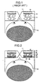
- the HMD is a spectacle-like case mountable on the user's head, wherein paired back lights, liquid-crystal displays (LCDs) and lenses are disposed in the described order from the front external side of the case (Fig. 1).
- LCDs liquid-crystal displays
- the viewer who wears the HMD on own head can view an image on the LCDs through the lenses in an enlarged scale as if it would be displayed on a large screen.
- US 4, 785, 053 discloses a composite optical resin having low birefringence.
- the optical device comprises a liquid crystal display (LCD) panel, a first polarizer plate, a plano-convex lens having a half-mirror coating on its convex surface, a first quarter-wave plate, a half-mirror, a second quarter-wave plate and a second polarizer plate, all of which are arranged in the described order from the incident side so that they are included in the x-y plane and are normal to the optical axis of the optical unit (Fig. 4).
- LCD liquid crystal display
- the directions of the optical elements are as follows (Fig. 5): the first and second polarizer plates are disposed to direct transmitting polarized light to the y-axis direction and the first and second quarter-wave plates are disposed so that their extension axes make an angle of -45 degrees with the y-axis.
- Incident light from the LCD disposed at the left side enters into the first polarizer plate whereby it is polarized to the y-axis direction.
- the polarized light passes a half-mirror-coated plano-convex-lens and then the first quarter-wave plate whereby the plane-polarized light is converted into circularly polarized light.
- the light is then divided by the half-mirror into directly transmitting light 41 and reflected light 42.
- the direct light is converted again by the second quarter-wave plate from the circularly polarized light into the plane-polarized light.
- the respective stretch-giving axes of the first quarter-wave plate and the second quarter-wave plate have the same direction the light is the same as passed a half-wave plate.
- the plane-polarized light is rotated by 90° and directed in the x-axis direction.
- the light passes for the third time the plano-convex lens and then the first quarter-wave plate whereby it is converted to circularly polarized light which further enters into the half-mirror and is divided into two parts: one passes the half-mirror and the other is reflected therefrom.
- the transmitted light then passes the second quarter-wave plate whereby it is converted to plane-polarized light.
- the plane-polarized light is confined to the y-axis direction since it passed through the first quarter-wave plate two more times. Consequently, it passes the second polarizing plate and reaches the user's eye.
- a HMD is particularly requested to have a reduced thickness (protrusion from the user's face) and a reduced weight loading the user's face so as to be comfortably used.
- the above-described optical device is effectively usable for HMDs.
- each optical element has not ideal characteristic and produces unnecessary noise light, decreasing a S/N-ratio of the optical system.
- Noise rays are produced for the following six main reasons:
- the present invention relates to an optical system as defined in claims 1 or 5 adapted to use in an image display device and, more particularly, to a small light-weighted super-wide-angle optical device and a HMD using said optical system.
- the present invention was made to provide a short focal optical device having a super-wide-field-of-vision for obtaining a wide-angle visual information with an improved S/N-ratio and a HMD using said optical device, which can provide a high-quality image that may give an observer an increased feeling of his presence therein.
- a HMD constituted as shown in Fig. 1 has attracted public attention as an image display which can be used for representing visual information of virtual reality, remote control of a robot and so on.
- HMD devices of this type are required to have so high-resolution and wide-field-of-vision that may provide video information with an enhanced impression of reality and the presence. It shall be also light and small so that a user may easily mount it on his or her body (particularly on the head) with no trouble.
- the HMD is a spectacle-like case 11 mountable on the user's head, wherein paired back lights 12, liquid-crystal displays (LCDs) 13 and lenses 14 are disposed in the described order from the front external side of the case 11.
- LCDs liquid-crystal displays
- the viewer 15 who wears the HMD on own head can view an image on the LCDs through the lenses 14 in an enlarged scale as if it would be displayed on a large screen.
- HMDs have been mainly applied in the industrial fields, in particular, as devices for studying of virtual reality.
- HMD devices find wide and increasing application for home-use game-machines, VTR displays and so on. Therefore, there is a keen interest in further development of more compact and light-weighted HMDs.
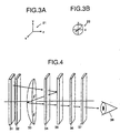
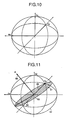
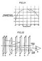
- coordinates 21 used for explaining the optical device is defined as follows: an axis being normal to the shown sheet plane and directed this side is x-axis, an axis being parallel to the sheet plane and directed upward is y-axis and an axis being normal to x-axis and y-axis and directed to the right is z-axis.
- a rotation angle 22 is an angle formed between y-axis and x-y plane when observing along z-axis.
- the direction of clockwise rotation is defined as a positive rotational direction.
- a unit of the optical device comprises a liquid crystal display (LCD) panel 31, a first polarizer plate 32, a plano-convex lens 33 having a half-mirror coating on its convex surface, a first quarter-wave plate 34, a half-mirror 35, a second quarter-wave plate 36 and a second polarizer plate 37, all of which are arranged in the described order from the incident side (left side in Fig. 4) so that they are included in the x-y plane and are normal to the optical axis of the optical unit.
- LCD liquid crystal display
- the directions of the optical elements are as follows: the first and second polarizer plates 32, 37 are disposed to direct transmitting polarized light to the y-axis direction and the first and second quarter-wave plates 34, 36 are disposed so that their extension axes make an angle of -45 degrees with the y-axis.
- Fig. 5 depicts how the optical unit acts on light rays.
- Incident light from the LCD 31 disposed at the left side enters into the first polarizer plate 32 whereby it is polarized to the y-axis direction.
- the polarized light passes a half-mirror-coated plano-convex-lens 33 and then the first quarter-wave plate 34 whereby the plane-polarized light is converted into circularly polarized light.
- the light is then divided by the half-mirror 35 into directly transmitting light 41 and reflected light 42.
- the direct light 41 is converted again by the second quarter-wave plate 36 from the circularly polarized light into the plane-polarized light.
- the first quarter-wave plate 34 and the second quarter-wave plate 36 have the same derection the light is the same as passed a half-wave plate.
- the plane-polarized light is rotated by 90° and directed in the x-axis direction.
- the light alters its polarization direction by 90° at every time when passing the first and second quarter-wave plates 34, 36 and is, therefore, absorbed by the second polarizer plate 37.
- noise light 41 from the LCD 31 can be shut off before reaching the user's eye 38.
- the reflected light 42 from the half-mirror 35 passes again the first quarter-wave plate whereby it is converted to plane-polarized light directed in the x-axis direction.
- the plane-polarized light passes the plano-convex lens 33 and is reflected from the half-mirror coating thereof.
- the polarization direction of the light is not changed by reflection. Accordingly, the light is left as plane-polarized.
- the light passes for the third time the plano-convex lens 33 and then the first quarter-wave plate 34 whereby it is converted to circularly polarized light which further enters into the half-mirror 35 and is divided into two parts: one passes the half-mirror 35 and the other is reflected therefrom.
- the transmitted light then passes the second quarter-wave plate 36 whereby it is converted to plane-polarized light.
- the plane-polarized light is confined to the y-axis direction since it passed through the first quarter-wave plate two more times. Consequently, it passes the second polarizer plate 37 and reaches the user's eye 38.
- a HMD is particularly requested to have a reduced thickness (protrusion from the user's face) and a reduced weight loading the user's face so as to be comfortably used.
- the above-described optical device is effectively usable for HMDs.
- each optical element has not ideal characteristic and produces unnecessary noise light, decreasing a S/N-ratio of the optical system.
- Noise rays are produced for the following six main reasons:
- the first embodiment is explained referring to Fig. 25 showing a plan view of a head-mounted display (HMD) using an optical system that is the first embodiment.
- HMD head-mounted display
- Fig. 25 is illustrative of an image display device, which is applied to a HMD used for displaying an image of virtual reality.
- the HMD using the optical device comprises a spectacle-like case 11 which accommodates two display units disposed by one at left and right therein: each display unit is composed of a back light 12, a liquid-crystal display (LCD) 31, a first polarizer plate 32, a plano-convex lens having a half-mirror coat applied onto its convex surface (reflecting-refracting means) 133, a first quarter-wave plate 34, a half-mirrors 35, a second quarter-wave plate 36 and a second polarizer plate 37, which are aligned in said order from the out side (opposite to the side facing a user 15) of the case.
- LCD liquid-crystal display
- first polarizer plate a plano-convex lens having a half-mirror coat applied onto its convex surface (reflecting-refracting means) 133, a first quarter-wave plate 34, a half-mirrors 35, a second quarter-wave plate 36 and a second
- the user 15 mounts the HMD on own head so that his or her eyes position in front of respective display units in the case 11.
- Video on the LCD 31 is enlarged and presented to the user who can enjoy the enhanced impression of the video image, feeling the presence therein.
- plano-convex lens 133 made of copolymerized macromolecular material having both positive and negative photoelastic coefficients relative to an inner stress.
- material is, e.g., non-birefringent resin material for optics, which is disclosed by the name Optolets by Hitachi Kasei Kogyo CO., LTD.
- noise light is distinguished from signal light by its polarized state as described before in the device. Accordingly, the system using a lens having so large photoelastic coefficients to disturb the polarized state of light may impair the quality of a display image because the polarizer plate allows a part of noise light to pass and shuts off a part of signal light.
- glass has a small photoelastic coefficient and is suitable to use but it may be not sufficiently light.
- a HMD with a weighty lens system may have its gravity center shifted downward, applying a load onto a nose of the user. The user may feel further unpleasant force whenever he or she rotates own head with the HMD.
- Acrylic resin is lighter but has a large photoelastic coefficient. Acrylic resin-made lenses produced by injection molding may obtain an undesired birefringent property.
- plano-convex lens 133 which is made of copolymerized macromolecular non-birefringent material having positive and negative photoelastic coefficients to an internal stress, makes it possible to manufacture a lighter HMD which can also provide an image with an improved S/N-ratio because light may not be disturbed in its polarized state while passing the plano-convex lens 133.
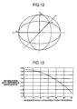
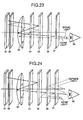
- the shown embodiment of the optical device of the HMD includes two (first and second) quarter-wave plates 134 and 136 with a refractive index in the thickness direction, which value lies between the maximal and minimal refractive values obtained within the wave-plate surface.
- These quarter-wave plates are disposed so that their stretch-giving axes may intersect with each other at right angles.
- the first and second quarter-wave plates 134 and 136 have a refractive index n z in the thickness direction, which value lies between refractive indexes n x and n y on the plate surface.
- this graph of Fig. 28 proves that the quarter-wave plate having refractive index in the thickness direction can considerably reduce a change of retardation. Accordingly, the application of these quarter-wave plates 134 and 136 can realize an optical system with an improved S/N-ratio.
- the first and second quarter-wave plates 134 and 136 are disposed with their stretch-giving axes intersecting with each other at right angles. Namely, the stretch-giving axes 61 and 63 of the first and second quarter-wave plates 134 and 136 are tilted at +45 degrees and -45 degrees respectively to the transmission axis 62 of a first polarizer plate 32 as shown in Fig. 27.
- the first and second quarter-wave plates 134 and 136 thus arranged can cooperatively cancel the retardation of light passing therethrough. Therefore, light from the first polarizer plate 32 passes the first and second quarter-wave plates 134 and 136 and emerges therefrom as polarized in a direction corresponding to the transmission axis direction of the first polarizer plate 32.
- the second polarizer plate 137 disposed with its transmission axis 64 intersecting at right angles with the transmission axis 62 of the first polarizer plate 32 can absorb light rays that may be directly transmitted from the LCD to the user's eye as noise light.
- Signal light enlarged by the plano-convex lens 33 is emitted through the second quarter-wave plate 136 as light polarized in a plane normal to the noise light.
- the signal light then passes the second polarizer plate 137 and reaches the user's eye 38.
- the earlier optical device of Fig. 14 and the present embodiment of Fig. 27 may perform the same function. However, actual quarter-wave plate varies the retardation with wavelength and, therefore, the earlier optical device produces noise light.
- the optical system according to the present embodiment has the first and second quarter-wave plates 134, 136 with their stretch-giving axes intersecting with each other at right angles, which can, cancel by each other their retardation characteristics, thus making retardation be zero irrespective of wavelength of light as shown on the graph of Fig. 29. Consequently, all rays having directly passed the quarter-wave plates can be absorbed by the second polarizer plate 137 disposed after the second quarter-wave plate 136, preventing the occurrence of noise light.
- the optical device according to the present embodiment can produce an image of an improved S/N-ratio by reducing noise rays by disposing the first and second quarter-wave plates 134 and 136 with their extension axes 61 and 63 intersecting with each other at right angles.
- each optical unit of their optical device includes a LCD 31, a first polarizer plate 32, a plano-convex lens (reflecting-refracting means) 133, a first quarter-wave plate 134, a half-mirror 35, a second quarter-wave plate 136 and a second polarizer plate 137, which are disposed in said order from the incident side.
- an optical device according to the present invention is not limited to the above-mentioned arrangement of components.
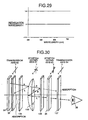
- FIG. 30 is illustrative of an arrangement of optical elements composing an optical unit of the optical device used in the third embodiment.
- an optical unit comprises a LCD 31, a first polarizer plate 32, a first quarter-wave plate 134, a half-mirror-coated plano-convex lens (reflecting and refracting means) 133, a second quarter -wave plate 136, a half-mirror 35 and a second polarizer plate, which are disposed in said order from the incident side.
- this embodiment disposes the transmission axis 62 of the first polarizer plate 32 at 0 degree, the stretch-giving axis 61 of the first quarter-wave plate 134 at 45 degrees, the stretch-giving axis of the second quarter-wave plate 136 at -45 degrees and the transmission axis 64 of the second polarizer plate 137 at +90 degrees.
- light from the LCD 31 passes the plano-convex lens 133 and the second quarter-wave plate 136 and enters into the half-mirror whereby light is split into two rays: transmitted light and reflected light.
- the transmitted light is plane-polarized in the zero-degree direction and absorbed by the second polarizer plate 137.
- the light reflected from the half-mirror 35 is converted again to clockwise circularly polarized light by the second quarter-wave plate 136 and then reflected from half-mirror surface of the plano-convex lens 133, thereby it becomes counterclockwise circularly polarized light.
- This counterclockwise circularly polarized light is then converted by the second quarter-wave plate 136 to plane-polarized light in the direction of +90 degrees, which passes through the second polarizer plate 137 and reaches the user's eye 38.
- the present embodiment can effectively enlarge an image displayed on the LCD 31 by the half-mirror-coated plano-convex lens 133 through the above-mentioned process.
- the advantageous feature of the present embodiment is as follows:
- the optical device of the present embodiment can convert the reflected light from the half-mirror coated surface of the plano-convex lens 133 to a counterclockwise circularly-polarized light and absorb it by the first polarizer plate 32, thus preventing the occurrence of noise light.
- the second embodiment (afore mentioned) of the present invention can considerably reduce an amount of noise light but does not much improve its characteristic of signal light.
- the spectral transmittance of the optical unit is desirably constant within the range of visible-light wavelengths to increase color reproducibility of the display.
- the retardation of light therein varies with wavelengths and, therefore, light of wavelength other than the designed value is converted into elliptically polarized light, resulting in decreasing the transmittance.
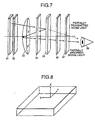
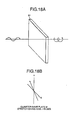
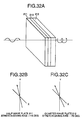
- the optical device of the present embodiment uses, instead of the first and second quarter-wave plates 34 and 36 of earlier simple constructed device, two (first and second) wideband-wave plates 234 and 236 (Fig. 31) each of which is prepared by bonding a quarter-wave plate with a half-wave plate at a specified angle.
- the wideband-wave plates 234 and 236 used in the present invention are composed each of a half-wave plate 211 and a quarter-wave plate 212, which are bonded to each other with bonding material 213.
- the half-wave plate 211 has its stretch-giving axis disposed in the direction of -15 degrees and the quarter-wave plate has its stretch-giving axis disposed in the direction of -75 degrees.
- the half-wave plate 211 and the quarter-wave plate 212 can be prepared by stretching (drawing) a high-polymer film.
- the plates used in the present invention are made of polycarbonate that is well used as a material for retardation plates.
- the wideband-wave plates 234 and 236 are designed to act as a quarter-wave plate having an improved wavelength dispersion characteristic when plane-polarized light confined to the normal plane (0°) enters the wideband-wave plate 234 (236) from the half-wave plate side. Accordingly, they can convert the light into substantially circularly-polarized light irrespective of wavelength within the range of visible rays (400 nm - 700 nm).
- the application of these wideband-wave plates in place of the conventional simple quarter-wave plates can therefore realize a considerable improvement of the spectral transmittance characteristic of the optical device.
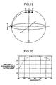
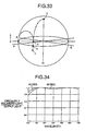
- the optical activity of the wideband-wave plates 234 and 236 used in the present embodiment will be explained below by using the Poincare's sphere shown in Fig. 33.
- the wideband-wave plates 234 and 236 are composed each of a half-wave plate 211 having its stretch-giving axis of -15 degrees and a quarter-wave plate 212 having its stretch-giving axis of -75 degrees.
- the stretch-giving axis of the half-wave plate 211 is represented by a line F
- the stretch-giving axis of the quarter-wave plate 212 is represented by a line G.
- the half-wave plate 211 rotates the plane of polarized light by 180° while the quarter-wave plate 212 rotates the plane of polarized light by 90°.
- Incident plane-polarized light confined to the normal plane is represented by a point A on the Poincare's sphere.
- Incident light whose wavelength corresponds to a reference wavelength is transferred to a point H by the quarter-wave plate 211 and then transferred to a point C (north pole) by the quarter-wave plate 212.
- the light is completely converted to counterclockwise circularly-polarized light that can also be obtained by simple quarter-wave plate.
- the half-wave plate 211 With incident light of a wavelength shorter than the reference wavelength, the half-wave plate 211 excessively retards and shifts the light to a point J (with a deviation from the point H) but the quarter-wave plate 212 compensates the deviation by its excessive retardation and brings the light close to the point C. With incident light of a wavelength longer than the reference wavelength, the half-wave plate 211 insufficiently retards and transfers the light to a point K (with a deviation from the point H) but the quarter-wave plate 212 compensates the deviation by its insufficient retardation and brings the light close to the point C. Thus, the incident light of any wavelength can be converted to substantially counterclockwise circularly-polarized light.
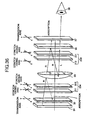
- the characteristics of the wideband-wave plates 234 and 236 was analyzed by ratios of circularly-polarized rays contained in output light. The analysis results are plotted on the graph of Fig. 34. In comparison with the graph of Fig. 20 for conventional simple quarter-wave plates, the graph of Fig. 34 clearly indicates that the wideband-wave plates 234 and 236 have an improved uniform wavelength-dispersion characteristic.
- the wideband-wave plates 234 and 236 can be further improved in their wavelength-dispersion characteristics by changing an angle between stretch-giving axes of its components, i.e., the half-wave plate 211 and the quarter-wave plate 212.
- the graph of Fig. 34 also indicates the characteristic of a wideband-wave plate wherein the half-wave plate 211 and the quarter-wave plate 212 are disposed at an angle of 55° between their stretch-giving axes.
- the wideband-wave plate (55°) is excellent in uniformity of the characteristic within the range of visible light wavelengths (200 nm - 700 nm) as compared with that of the wideband-wave plate (60° as described (b) in Fig. 32).
- the wideband-wave plate can be adapted to required specifications (e.g., necessary wavelength band) by adjusting an angle formed between stretch-giving axes of the half-wave plate and the quarter-wave plate.
- Fig. 35 is a graph showing a spectral transmittance characteristic of signal light obtained of the optical device using the above-mentioned wideband-wave plates 234 and 236.
- the optical unit using the wideband-wave plates 234 and 236 has an improved transmittance of blue light and red light and attains further uniform spectral transmittance within the range of visible light wavelengths.
- the embodiment can obtain an improved characteristic for signal light slantingly passing through the optical device as described for the first embodiments. This feature further increases the effectiveness of the shown embodiment.
- the optical device according to the present invention uses an optical device wherein a LCD 31, a first polarizer plate 32, a plano-convex lens 33, a first wideband-wave plate 234, a half-mirror 35, a second wideband-wave plate 236 and a second polarizer plate 37 are arranged in the described order from the incident side, the optical device according to the present invention is not limited to the above-mentioned arrangement of its optical components.
- FIG. 36 an example of an optical device composed of differently arranged optical elements is described as follows:
- the optical device shown in Fig. 36 comprises a LCD 31, a first polarizer plate 32, a first wideband-wave plate 234 consisting of a first half-wave plate 211 and a first quarter-wave plate 212, a plano-convex lens 33, a second wideband-wave plate 236 consisting of a second half-wave plate 211 and a second quarter-wave plate 212, a half-mirror 35, and a second polarizer plate 37, which are arranged in the described order from the incident side of the system.
- the stretch-giving axes of the first half-wave plate 211 and the first quarter-wave plate 212 are directed to +15° and +75° respectively while the stretch-giving axes of the second half-wave plat 211 and the second quarter-wave plate 212 are directed to -15° and -75° respectively.
- the half-wave plate 211 and the quarter-wave plate 212 are bonded to each other at a specified angle that differs from the angle shown for the wideband-wave plate of Fig. 32. This means that the angle at which the half-wave plate 211 and the quarter-wave plate 212 are bonded to each other is not limited to the value shown in Fig. 32.
- the wideband-wave plate 234 of Fig. 36 converts plane-polirized light to clockwise circularly-polarized light while the wideband-wave plate shown in Fig. 32 converts plane-polarized light to clockwise circularly-polarized light.
- This embodiment may be realized by modifying the third embodiment by replacing the quarter-wave plates with the wideband-wave plates. Accordingly, the present optical device works to enlarge an image of the LCD 31 in the same way that the third embodiment does. Owing to uniform characteristics of the retardation plates, the present optical device is superior to the third embodiment in that retardation plates have uniform wavelength characteristics and can reduce noise light in a wide band of wavelengths with an improved S/N-ratio.
- the first wideband-wave plate 234 and the first polarizer plate 32 cooperatively act as a circularly-polarizer plate and can widely absorb rays reflected from the half-mirror coated surface of the plano-convex lens 33 with result that reflection at LCD is reduced and a S/N-ratio of an image of the LCD is further improved as compared with the third embodiment.
- the fifth embodiment will be described below with reference to Fig. 37 showing an optical device according to the fifth embodiment.
- All optical elements composing the optical unit according to the present embodiment are coated with anti-reflection coating.
- the earlier optical device produces noise light by unnecessary reflection at a viewer-side surface of a plano-convex lens 33 and both sides of a first quarter-wave plate 34.
- the optical components are coated with an anti-reflection layer or bonded to another component with adhesive for optics.
- polycarbonate of the quarter-wave plate may not stably bear anti-reflection coat. Accordingly, an element 301 made of acrylic sheet with an anti-reflection coating is bonded to each surface of the first quarter-wave plate 34 made of polycarbonate, as shown in Fig. 37.
- a second quarter-wave plate 36 is bonded to a half-mirror 35 (not to a plano-convex lens 33) as shown in Fig. 37, for easy examination of the plano-convex lens 33.
- a half-mirror 35 not to a plano-convex lens 33
- Fig. 37 for easy examination of the plano-convex lens 33.
- Another combination of components to be bonded can be, of course, possible.
- the earlier optical device produces noise light by unnecessary reflection from the black matrix of the LCD 31.
- the present embodiment uses a LCD 31 whose black-matrix is coated with a chrome coat, thus reducing the reflectance of the black matrix to 5% or less.
- the first polarizer plate 32 is bonded to the glass of the LCD 31, as shown in Fig. 37, and has an anti-reflection coat on its surface facing to the plano-convex lens 33 to prevent unnecessary reflection of light therefrom.
- the earlier optical device produces noise light caused by reflection from the second quarter-wave plate 36, the second polarizer plate 37 and the rear surface of the half-mirror 35.
- the half-mirror 35, the second quarter-wave plate 36 and the second polarizer plate 37 are bonded to each other and the outside surface of the second polarizer plate 37 is coated with an anti-reflection coat in the present embodiment.
- the optical unit of the present embodiment since its components are coated with anti-reflection coatings can provide a high-quality image by minimizing noise rays to be caused by unnecessary reflection.
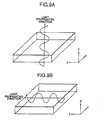
- Fig. 38 is a schematic construction plan view for explaining a HMD embodying the present invention
- Fig. 39 is a schematic perspective illustration of an essential portion of a back light of the HMD
- Fig. 40 is a grossly enlarged sectional side view of an essential portion of a back light of the HMD.
- emitting diodes 402 must be densely mounted on the substrate since each diode can emit not sufficiently bright light. Accordingly, an example of designing arrays of these blue-light emitting diodes 402 for a LCD of 1.3 inches in size.
- a LED 402 is supposed to emit light whose brightness is 40 mcd at a DC forward voltage of 3.6V and a DC forward current of 20 mA.
- Anther optical device is characterized in that the first second quarter-wave plates have refractive power in their thickness direction, which value lies within a maximal refractive index and a minimal refractive index within the plate surface.
- the first quarter-wave plate and the second quarter-wave plate can suppress a change in retardation of light slanted into respective plates, reducing noise rays that may obliquely entering the user's eye and surrounds an image produced by signal light.
- Another optical device is characterized in that an angle "p" formed between optical axes of the quarter-wave plate and the half-wave plate is larger than 50 degrees and smaller than 70 degrees. This construction can further improve the uniformity of wavelength characteristics of the wide-band-wave plate, thus increasing a S/N-ratio of an image to be provided by the device.
- Another optical device is characterized in that the first wide-band-wave plate and the first polarizer plate cooperatively work as a wide-band-wave circularly polarizer plate that can absorb wide-band noise light reflected from reflecting and refracting means, thus improving a S/N-ratio of an image formed by signal light having passed the device.
- optical device is characterized in that the optical components have an anti-reflection coat, thus reducing an amount of noise light resulted from unnecessary reflection.
- Another optical device is characterized in that the optical components are bonded to each other with adhesive for optics, thus reducing an amount of noise light resulted from unnecessary reflection.
- An HMD according to the present invention is composed of any one of the above-mentioned optical device, a back light and a liquid-crystal display (LCD). It has a wide-field angle and is a thin and light to comfortably wear and can provide a high-quality image.
- LCD liquid-crystal display
- Another HMD is characterized in that a black-matrix contained in the liquid crystal display has been subjected to anti-reflection processing. This feature can reduce an amount of noise light caused by reflection on the LCD, thus realizing a further improved image quality of the HMD.
- Another HMD according to the present invention comprises any one of the above-mentioned optical devices and an electroluminescent display (ELD).
- ELD electroluminescent display
- this HMD has no need of using a back light and may be further compact.
- Another HMD is characterized in that a black-matrix contained in the electroluminescent display has been subjected to anti-reflection processing. This feature can reduce an amount of noise light caused by reflection on the ELD, thus attaining a further improved image quality of the HMD.
Landscapes
- Physics & Mathematics (AREA)
- General Physics & Mathematics (AREA)
- Optics & Photonics (AREA)
- Polarising Elements (AREA)
- Liquid Crystal (AREA)
Claims (16)
- Dispositif optique comportant une première lame polarisante (32) disposée au niveau d'un côté d'incidence et une seconde lame polarisante (37, 137) disposée au niveau d'un côté de sortie, les axes de transmission respectifs des deux lames polarisantes étant disposés perpendiculairement l'un à l'autre, lames entre lesquelles sont disposés des moyens d'agrandissement à réflexion - réfraction revêtus d'un semi-miroir (33, 133), une première lame quart d'onde (34, 134), un semi-miroir (35), et une seconde lame quart d'onde (36, 136), dans lequel les axes optiques des deux lames quart d'onde (34, 36 ; 134, 136) sont inclinés suivant un angle de + ou - 45° par rapport aux axes optiques correspondants des deux lames polarisantes, et caractérisé en ce que lesdites première et seconde lames quart d'onde satisfont chacune la condition nx > nz > ny, condition dans laquelle nz est l'indice de réfraction dans le sens de l'épaisseur, et nx, ny sont les indices de réfraction dans les directions de plan de surface orthogonales des lames quart d'onde respectives, de manière à supprimer en coopération une variation du retard de la lumière, par rapport à l'angle d'incidence de la lumière, traversant obliquement lesdites lames quart d'onde.
- Dispositif optique selon la revendication 1, dans lequel la première lame quart d'onde (34, 134) et la seconde lame quart d'onde (36, 136) sont disposées de manière à ce que leurs axes optiques soient perpendiculaires l'un à l'autre de façon à réduire en coopération une variation, dépendante de la longueur d'onde, du retard de la lumière traversant lesdites lames quart d'onde.
- Dispositif optique selon la revendication 1 ou la revendication 2, dans lequel la première lame polarisante (32), les moyens d'agrandissement à réflexion - réfraction (33, 133), la première lame quart d'onde (34, 134), le semi-miroir (35), la seconde lame quart d'onde (36, 136) et la seconde lame polarisante (37, 137) sont disposés, dans ledit ordre, à partir du côté d'incidence.
- Dispositif optique selon la revendication 1 ou la revendication 2, dans lequel la première lame polarisante (32), la première lame quart d'onde (34, 134), les moyens d'agrandissement à réflexion - réfraction (33, 133), la seconde lame quart d'onde (36, 136), le semi-miroir (35) et la seconde lame polarisante (37, 137) sont disposés, dans ledit ordre, à partir du côté d'incidence.
- Dispositif optique comportant une première lame polarisante (32) disposée au niveau d'un côté d'incidence et une seconde lame polarisante (37, 137) disposée au niveau d'un côté de sortie, les axes de transmission respectifs des deux lames polarisantes étant disposés perpendiculairement l'un à l'autre, lames entre lesquelles sont disposés des moyens d'agrandissement à réflexion - réfraction revêtus d'un semi-miroir (33, 133), une première lame à retard (234), un semi-miroir (35), et une seconde lame à retard (236), caractérisé en ce que chacune desdites lames à retard (234, 236) est une lame onde à large bande respective formée à partir d'une lame quart d'onde (212) et d'une lame demi-onde (211) qui sont unies l'une à l'autre et dont les axes optiques se croisent de manière à ce qu'elles convertissent la lumière en une lumière à polarisation sensiblement circulaire quelle que soit la longueur d'onde de la lumière, et en ce que la lame quart d'onde (212) et la lame demi-onde (211) sont faites de la même sorte de matériau et au moins l'une ou l'autre des lames onde satisfait la condition nx > nz > ny, condition dans laquelle nz est l'indice de réfraction dans le sens de l'épaisseur, et nx, ny sont les indices de réfraction dans les directions de plan de surface orthogonales des lames onde, de manière à supprimer en coopération une variation du retard de la lumière, par rapport à l'angle d'incidence de la lumière, traversant obliquement lesdites lames onde à large bande.
- Dispositif optique selon la revendication 5, dans lequel un angle « p » formé entre les axes optiques de la plaque quart d'onde (212) et de la plaque demi-onde (211) est supérieur à 50 degrés et inférieur à 70 degrés.
- Dispositif optique selon la revendication 5 ou la revendication 6, dans lequel la première lame polarisante (32), les moyens d'agrandissement à réflexion - réfraction (33, 133), la première lame onde à large bande (234), le semi-miroir (35), la seconde lame onde à large bande (236) et la seconde lame polarisante (37, 137) sont disposés, dans ledit ordre, à partir du côté d'incidence.
- Dispositif optique selon la revendication 5 ou la revendication 6, dans lequel la première lame polarisante (32), la première lame onde à large bande (234), les moyens d'agrandissement à réflexion - réfraction (33, 133), la seconde lame onde à large bande (236), le semi-miroir (35) et la seconde lame polarisante (37, 137) sont disposés, dans ledit ordre, à partir du côté d'incidence.
- Dispositif optique selon l'une quelconque des revendications 1 à 8, dans lequel les composants optiques comportent chacun sur l'une ou l'autre de leur face un revêtement anti-réfléchissant.
- Dispositif optique selon l'une quelconque des revendications 1 à 8, dans lequel les deux composants optiques d'une paire quelconque de composants optiques sont unis l'un à l'autre à l'aide d'un adhésif pour surfaces optiques.
- Dispositif optique selon l'une quelconque des revendications 1 à 10, dans lequel les moyens d'agrandissement à réflexion - réfraction (33, 133) sont élaborés à partir de copolymère de composés à haut poids moléculaire ayant des coefficients de photoélasticité positifs et négatifs par rapport à des tensions internes de façon à éliminer une double réfraction à l'intérieur.
- Visiocasque qui comprend un dispositif optique selon l'une quelconque des revendications 1 à 11, un dispositif de rétroéclairage (12, 112) et un afficheur à cristaux liquides (31).
- Visiocasque selon la revendication 12, dans lequel une matrice à fond noir contenue dans l'afficheur à cristaux liquides (31) est dotée de moyens anti-réfléchissants.
- Visiocasque selon la revendication 12 ou la revendication 13, dans lequel le dispositif de rétroéclairage (112) comporte un substrat (401) sur lequel est prévue une puce à diodes électroluminescentes (402), une électrode et un matériau fluorescent (403) étant appliqués sur le substrat (401).
- Visiocasque qui comprend un dispositif optique selon l'une quelconque des revendications 1 à 11 et un afficheur électroluminescent.
- Visiocasque selon la revendication 15, dans lequel une matrice à fond noir contenue dans l'afficheur électroluminescent est dotée de moyens anti-réfléchissants.
Applications Claiming Priority (6)
| Application Number | Priority Date | Filing Date | Title |
|---|---|---|---|
| JP102826/96 | 1996-04-24 | ||
| JP10282696 | 1996-04-24 | ||
| JP10282696 | 1996-04-24 | ||
| JP00271897A JP3411953B2 (ja) | 1996-04-24 | 1997-01-10 | 光学装置および該光学装置を用いた頭部搭載型ディスプレイ |
| JP2718/97 | 1997-01-10 | ||
| JP271897 | 1997-01-10 |
Publications (2)
| Publication Number | Publication Date |
|---|---|
| EP0803756A1 EP0803756A1 (fr) | 1997-10-29 |
| EP0803756B1 true EP0803756B1 (fr) | 2003-04-02 |
Family
ID=26336174
Family Applications (1)
| Application Number | Title | Priority Date | Filing Date |
|---|---|---|---|
| EP97302820A Expired - Lifetime EP0803756B1 (fr) | 1996-04-24 | 1997-04-24 | Dispositif d'observation pour visiocasque |
Country Status (4)
| Country | Link |
|---|---|
| US (1) | US5966242A (fr) |
| EP (1) | EP0803756B1 (fr) |
| JP (1) | JP3411953B2 (fr) |
| DE (1) | DE69720313T2 (fr) |
Cited By (2)
| Publication number | Priority date | Publication date | Assignee | Title |
|---|---|---|---|---|
| TWI715145B (zh) * | 2019-08-12 | 2021-01-01 | 宏碁股份有限公司 | 具有雙對焦平面的虛擬實境光學裝置 |
| US12233613B2 (en) | 2015-09-03 | 2025-02-25 | 3M Innovative Properties Company | Optical system |
Families Citing this family (95)
| Publication number | Priority date | Publication date | Assignee | Title |
|---|---|---|---|---|
| JP4101943B2 (ja) * | 1998-08-07 | 2008-06-18 | オリンパス株式会社 | 画像表示装置 |
| US6271969B1 (en) | 1998-12-11 | 2001-08-07 | Agilent Technolgoies, Inc. | Folded optical system having improved image isolation |
| US6483484B1 (en) * | 1998-12-18 | 2002-11-19 | Semiconductor Energy Laboratory Co., Ltd. | Goggle type display system |
| US6075651A (en) * | 1999-01-28 | 2000-06-13 | Kaiser Electro-Optics, Inc. | Compact collimating apparatus |
| EP1110118A1 (fr) * | 1999-07-02 | 2001-06-27 | Koninklijke Philips Electronics N.V. | Casque-ecran |
| US6400493B1 (en) * | 1999-10-26 | 2002-06-04 | Agilent Technologies, Inc. | Folded optical system adapted for head-mounted displays |
| JP2003172925A (ja) * | 1999-10-29 | 2003-06-20 | Citizen Watch Co Ltd | 液晶表示装置 |
| WO2001063917A1 (fr) * | 2000-02-23 | 2001-08-30 | Olympus Optical Co., Ltd. | Visiocasque |
| JP2003529795A (ja) * | 2000-03-31 | 2003-10-07 | コーニンクレッカ フィリップス エレクトロニクス エヌ ヴィ | ヘッドマウントディスプレイ |
| US6344365B1 (en) * | 2000-05-26 | 2002-02-05 | Taiwan Semiconductor Manufacturing Company | Arc coating on mask quartz plate to avoid alignment error on stepper or scanner |
| JP3763401B2 (ja) * | 2000-05-31 | 2006-04-05 | シャープ株式会社 | 液晶表示装置 |
| WO2003102639A1 (fr) * | 2002-05-30 | 2003-12-11 | Zeon Corporation | Stratifie optique |
| US6853491B1 (en) * | 2003-11-26 | 2005-02-08 | Frank Ruhle | Collimating optical member for real world simulation |
| JP2004354936A (ja) * | 2003-05-30 | 2004-12-16 | Toyo Commun Equip Co Ltd | 積層波長板及びそれを用いた光ピックアップ |
| JP2005148655A (ja) * | 2003-11-19 | 2005-06-09 | Sony Corp | 画像表示装置 |
| FR2883078B1 (fr) * | 2005-03-10 | 2008-02-22 | Essilor Int | Imageur optique destine a la realisation d'un afficheur optique |
| GB2437553A (en) * | 2006-04-28 | 2007-10-31 | Sharp Kk | Optical system with two spaced apart partial reflectors for display |
| JP5438905B2 (ja) * | 2008-02-18 | 2014-03-12 | オリンパス株式会社 | 画像表示装置 |
| US9323061B2 (en) | 2012-04-18 | 2016-04-26 | Kopin Corporation | Viewer with display overlay |
| US9389425B2 (en) | 2012-04-18 | 2016-07-12 | Kopin Corporation | Viewer with display overlay |
| JP2014153425A (ja) * | 2013-02-05 | 2014-08-25 | Sony Corp | 表示装置、表示装置の製造方法および電子機器 |
| US9582075B2 (en) | 2013-07-19 | 2017-02-28 | Nvidia Corporation | Gaze-tracking eye illumination from display |
| US9880325B2 (en) | 2013-08-14 | 2018-01-30 | Nvidia Corporation | Hybrid optics for near-eye displays |
| WO2015125247A1 (fr) * | 2014-02-20 | 2015-08-27 | パイオニア株式会社 | Dispositif de projection |
| WO2016088709A1 (fr) * | 2014-12-01 | 2016-06-09 | 富士フイルム株式会社 | Rétroviseur de véhicule ayant une fonction d'affichage d'image |
| CN105093555B (zh) * | 2015-07-13 | 2018-08-14 | 深圳多新哆技术有限责任公司 | 短距离光学放大模组及使用其的近眼显示光学模组 |
| CN105572894B (zh) * | 2016-01-28 | 2018-05-04 | 深圳多哚新技术有限责任公司 | 一种短距离光学放大模组、放大方法及放大系统 |
| WO2017128183A1 (fr) * | 2016-01-28 | 2017-08-03 | 深圳多哚新技术有限责任公司 | Module d'amplification optique à courte distance, procédé d'amplification et système d'amplification |
| CN105629472A (zh) * | 2016-01-28 | 2016-06-01 | 深圳多哚新技术有限责任公司 | 短距离光学放大模组、放大方法及放大系统 |
| EP3410176A4 (fr) * | 2016-01-28 | 2019-09-18 | Shenzhen Dlodlo New Technology Co., Ltd. | Module amplificateur optique à courte distance, procédé d'amplification et système d'amplification |
| CN109313340A (zh) * | 2016-02-01 | 2019-02-05 | 寇平公司 | 嵌入式反射目镜 |
| CN105652460B (zh) * | 2016-03-21 | 2018-08-14 | 深圳多哚新技术有限责任公司 | 短距离光学放大模组、眼镜、头盔及vr系统 |
| CN105629494B (zh) * | 2016-03-21 | 2018-08-14 | 深圳多哚新技术有限责任公司 | 一种短距离光学放大模组、眼镜、头盔以及vr系统 |
| ES2883676T3 (es) * | 2016-03-21 | 2021-12-09 | Shenzhen Dlodlo New Tech Co Ltd | Módulo, gafas, casco y sistema de VR de aumento óptico a corta distancia |
| ES2875125T3 (es) * | 2016-03-21 | 2021-11-08 | Shenzhen Dlodlo New Tech Co Ltd | Módulo de aumento óptico de corta distancia, gafas, casco y sistema de RV |
| US10591739B2 (en) * | 2016-09-19 | 2020-03-17 | George M Calm | Near-eye-display with rapid spherical image scanning |
| US10310273B2 (en) * | 2016-09-19 | 2019-06-04 | George Mataban Calm | Near-eye-display (NED) that employs rapid spherical image scanning |
| JP7027035B2 (ja) * | 2016-11-15 | 2022-03-01 | 日東電工株式会社 | 光通信装置及び偏光板のセット |
| CN106444046A (zh) * | 2016-12-14 | 2017-02-22 | 浙江舜通智能科技有限公司 | 一种光学系统及装配该光学系统的头戴式显示装置 |
| CN106707510A (zh) * | 2016-12-14 | 2017-05-24 | 浙江舜通智能科技有限公司 | 隐形眼镜式的光学系统以及装配该光学系统的头戴显示器 |
| IL311431A (en) | 2017-02-23 | 2024-05-01 | Magic Leap Inc | Display system with variable power reflector |
| JP7129181B2 (ja) * | 2017-03-17 | 2022-09-01 | 旭化成株式会社 | ヘッドマウントディスプレイ用部材 |
| US20190018255A1 (en) * | 2017-07-11 | 2019-01-17 | Google Llc | Compact near-eye optical system including a refractive beam-splitting convex lens |
| JP6778823B2 (ja) * | 2017-07-19 | 2020-11-04 | 株式会社ソニー・インタラクティブエンタテインメント | 表示装置 |
| US20190025602A1 (en) * | 2017-07-20 | 2019-01-24 | Google Llc | Compact near-eye display optics for augmented reality |
| WO2019047006A1 (fr) * | 2017-09-05 | 2019-03-14 | 深圳市柔宇科技有限公司 | Module optique, dispositif électronique monté sur la tête et système de réalité virtuelle |
| JP7027748B2 (ja) * | 2017-09-14 | 2022-03-02 | セイコーエプソン株式会社 | 虚像表示装置 |
| JP6984261B2 (ja) * | 2017-09-14 | 2021-12-17 | セイコーエプソン株式会社 | 虚像表示装置 |
| US11054622B1 (en) | 2017-11-20 | 2021-07-06 | Facebook Technologies, Llc | Folded viewing optics with an optical retarder on a simple surface |
| CN107861247B (zh) * | 2017-12-22 | 2020-08-25 | 联想(北京)有限公司 | 光学部件及增强现实设备 |
| CN108169904A (zh) * | 2017-12-28 | 2018-06-15 | 重庆爱奇艺智能科技有限公司 | 一种用于进行信息显示的部件 |
| CN110007461A (zh) * | 2017-12-30 | 2019-07-12 | 深圳多哚新技术有限责任公司 | 光学系统 |
| CN109991742A (zh) * | 2017-12-30 | 2019-07-09 | 深圳多哚新技术有限责任公司 | 一种虚拟现实设备光学组件 |
| CN110161689A (zh) * | 2018-02-12 | 2019-08-23 | 杭州太若科技有限公司 | Ar显示装置和穿戴式ar设备 |
| JP7077656B2 (ja) | 2018-02-26 | 2022-05-31 | セイコーエプソン株式会社 | 虚像表示装置 |
| CN108445633A (zh) * | 2018-03-30 | 2018-08-24 | 京东方科技集团股份有限公司 | 一种vr头戴式显示设备、vr显示方法及vr显示系统 |
| CN108303796B (zh) * | 2018-04-09 | 2020-07-28 | 浙江舜宇光学有限公司 | 目镜 |
| US11226483B2 (en) | 2018-06-07 | 2022-01-18 | Facebook Technologies, Llc | Reverse-order crossed pancake lens with a shaped polarizer |
| CN110161692A (zh) * | 2018-07-16 | 2019-08-23 | 上海视涯信息科技有限公司 | 一种虚拟现实显示装置 |
| US10778963B2 (en) * | 2018-08-10 | 2020-09-15 | Valve Corporation | Head-mounted display (HMD) with spatially-varying retarder optics |
| US10996463B2 (en) | 2018-08-10 | 2021-05-04 | Valve Corporation | Head-mounted display (HMD) with spatially-varying retarder optics |
| WO2020035791A1 (fr) | 2018-08-14 | 2020-02-20 | 3M Innovative Properties Company | Système optique |
| US11022784B1 (en) * | 2018-08-17 | 2021-06-01 | Facebook Technologies, Llc | Use of folded optics to reduce volume in a virtual-reality system |
| US10816804B2 (en) * | 2018-08-31 | 2020-10-27 | Google Llc | Near-eye display system with polarization-based optical path folding and variable focus catadioptric lens assembly |
| US11885959B1 (en) | 2018-08-31 | 2024-01-30 | Apple Inc. | Optical system with ghost image mitigation |
| US11372239B1 (en) | 2018-11-01 | 2022-06-28 | Facebook Technologies, Llc | Enabling eye tracking in pancake lens optics |
| US20200159027A1 (en) * | 2018-11-20 | 2020-05-21 | Facebook Technologies, Llc | Head-mounted display with unobstructed peripheral viewing |
| CN110286489A (zh) * | 2019-06-26 | 2019-09-27 | 联想(北京)有限公司 | 穿戴设备 |
| CN114144716B (zh) * | 2019-07-22 | 2025-04-08 | 3M创新有限公司 | 用于显示放大虚像的光学系统 |
| CN112882134A (zh) * | 2019-11-29 | 2021-06-01 | 旭化成株式会社 | 头戴式显示器用树脂透镜 |
| CN114945856B (zh) * | 2020-01-15 | 2024-04-09 | 富士胶片株式会社 | 光学系统 |
| KR20220130809A (ko) | 2020-02-06 | 2022-09-27 | 밸브 코포레이션 | 머리-착용 디스플레이 시스템들에 대한 위치 추적 시스템 |
| JP7438811B2 (ja) * | 2020-03-26 | 2024-02-27 | キヤノン株式会社 | 光学系および画像表示装置 |
| CN111443491A (zh) | 2020-04-30 | 2020-07-24 | 京东方科技集团股份有限公司 | 一种光学显示系统及控制方法、显示装置 |
| CN212111989U (zh) * | 2020-05-27 | 2020-12-08 | 歌尔光学科技有限公司 | 光学系统及虚拟现实设备 |
| CN217506273U (zh) * | 2020-09-30 | 2022-09-27 | 上海悠睿光学有限公司 | 光学模组和近眼显示装置 |
| CN112630965B (zh) * | 2020-09-30 | 2025-03-14 | 上海悠睿光学有限公司 | 光学模组、近眼显示装置和光投射方法 |
| CN114690415A (zh) * | 2020-12-29 | 2022-07-01 | 华为技术有限公司 | 光学模组及电子设备 |
| US20230093721A1 (en) * | 2021-09-23 | 2023-03-23 | Valve Corporation | Head-mounted display system with compact optics |
| JP7731752B2 (ja) | 2021-09-30 | 2025-09-01 | キヤノン株式会社 | 接眼光学系及び画像表示装置 |
| CN114200685A (zh) * | 2021-11-22 | 2022-03-18 | 北京邮电大学 | 一种光学成像系统 |
| CN116243483A (zh) * | 2021-12-07 | 2023-06-09 | 四川龙华光电薄膜股份有限公司 | 增强现实显示系统及ar眼镜 |
| CN114415393A (zh) * | 2022-01-29 | 2022-04-29 | 于迅博 | 一种光学成像系统 |
| JP2024095089A (ja) * | 2022-12-28 | 2024-07-10 | 日東電工株式会社 | 表示システムおよび積層フィルム |
| JP2024095088A (ja) * | 2022-12-28 | 2024-07-10 | 日東電工株式会社 | 表示システムおよび積層フィルム |
| KR20240154571A (ko) * | 2022-03-14 | 2024-10-25 | 닛토덴코 가부시키가이샤 | 표시 시스템 및 적층 필름 |
| WO2023176693A1 (fr) * | 2022-03-14 | 2023-09-21 | 日東電工株式会社 | Système d'affichage, procédé d'affichage, corps d'affichage et procédé de fabrication de corps d'affichage |
| WO2023176660A1 (fr) * | 2022-03-14 | 2023-09-21 | 日東電工株式会社 | Système d'affichage et film stratifié |
| CN114675429B (zh) * | 2022-03-16 | 2025-10-17 | 北京邮电大学 | 一种光学成像系统及成像装置 |
| CN115047628B (zh) * | 2022-06-29 | 2024-07-30 | 京东方科技集团股份有限公司 | 显示系统及显示装置 |
| JP2024021515A (ja) * | 2022-08-03 | 2024-02-16 | 株式会社ジャパンディスプレイ | 表示装置及び表示システム |
| CN119472149B (zh) * | 2023-08-04 | 2025-10-31 | 宁波舜宇光电信息有限公司 | 基于OLEDoS显示芯片的光学系统 |
| WO2025057647A1 (fr) * | 2023-09-14 | 2025-03-20 | 日東電工株式会社 | Stratifié optique, et système d'affichage |
| WO2025057648A1 (fr) * | 2023-09-14 | 2025-03-20 | 日東電工株式会社 | Stratifié optique, et système d'affichage |
| WO2025245721A1 (fr) * | 2024-05-29 | 2025-12-04 | 瑞声声学科技(深圳)有限公司 | Système optique |
Family Cites Families (8)
| Publication number | Priority date | Publication date | Assignee | Title |
|---|---|---|---|---|
| US27356A (en) * | 1860-03-06 | Improvement in corn and cane harvesters | ||
| USRE27356E (en) | 1970-08-17 | 1972-05-09 | Infinite optical image-forming apparatus | |
| US4093347A (en) * | 1976-05-10 | 1978-06-06 | Farrand Optical Co., Inc. | Optical simulation apparatus using controllable real-life element |
| JPS61108617A (ja) * | 1984-11-02 | 1986-05-27 | Sumitomo Chem Co Ltd | 光学樹脂材料 |
| US4859031A (en) * | 1987-08-03 | 1989-08-22 | Kaiser Electronics | Optical collimating apparatus |
| JP2841095B2 (ja) * | 1990-01-25 | 1998-12-24 | チッソ株式会社 | 液晶配向膜及び液晶表示素子 |
| JP2916076B2 (ja) * | 1993-08-26 | 1999-07-05 | シャープ株式会社 | 画像表示装置 |
| JP3295583B2 (ja) * | 1994-12-19 | 2002-06-24 | シャープ株式会社 | 光学装置および該光学装置を用いた頭部搭載型ディスプレイ |
-
1997
- 1997-01-10 JP JP00271897A patent/JP3411953B2/ja not_active Expired - Fee Related
- 1997-04-15 US US08/843,352 patent/US5966242A/en not_active Expired - Fee Related
- 1997-04-24 DE DE69720313T patent/DE69720313T2/de not_active Expired - Fee Related
- 1997-04-24 EP EP97302820A patent/EP0803756B1/fr not_active Expired - Lifetime
Cited By (2)
| Publication number | Priority date | Publication date | Assignee | Title |
|---|---|---|---|---|
| US12233613B2 (en) | 2015-09-03 | 2025-02-25 | 3M Innovative Properties Company | Optical system |
| TWI715145B (zh) * | 2019-08-12 | 2021-01-01 | 宏碁股份有限公司 | 具有雙對焦平面的虛擬實境光學裝置 |
Also Published As
| Publication number | Publication date |
|---|---|
| DE69720313T2 (de) | 2003-12-11 |
| EP0803756A1 (fr) | 1997-10-29 |
| US5966242A (en) | 1999-10-12 |
| JPH1010465A (ja) | 1998-01-16 |
| DE69720313D1 (de) | 2003-05-08 |
| JP3411953B2 (ja) | 2003-06-03 |
Similar Documents
| Publication | Publication Date | Title |
|---|---|---|
| EP0803756B1 (fr) | Dispositif d'observation pour visiocasque | |
| JP3236304B2 (ja) | 反射型液晶表示装置 | |
| EP0718645B1 (fr) | Système optique et afficheur monté sur tête utilisant ledit système optique | |
| US6747716B2 (en) | Optical element including an absorptive and reflective polarizer having particular orientation | |
| US8208097B2 (en) | Color compensation multi-layered member for display apparatus, optical filter for display apparatus having the same and display apparatus having the same | |
| US7268841B2 (en) | Display device and electronic equipment having the same comprising a region for reflecting a polarized light and a region for absorbing the polarized light | |
| KR20040009894A (ko) | 액정 표시 장치 | |
| KR100695040B1 (ko) | 편광자, 편광광원장치 및 액정표시장치 | |
| CN117348287A (zh) | 偏光片以及显示装置 | |
| CN111856821A (zh) | 显示装置及电子设备 | |
| JP2023168875A (ja) | 液晶表示装置 | |
| JPH10260402A (ja) | 半透過反射型液晶装置及び電子機器 | |
| US12433140B2 (en) | Display and display system | |
| CN117170134A (zh) | 一种远景显示面板及显示装置 | |
| JPH0968706A (ja) | 液晶表示素子 | |
| JP4211341B2 (ja) | 表示装置及び電子機器 | |
| US8810753B2 (en) | Liquid crystal device and electronic apparatus | |
| CN223180495U (zh) | 透镜组件和显示装置 | |
| JPH11242214A (ja) | 液晶装置及び電子機器 | |
| JP2001356340A (ja) | タッチパネル一体型反射型液晶表示装置 | |
| JP4211342B2 (ja) | 表示装置及び電子機器 | |
| US11994765B2 (en) | Display with polarization dependent diffusive properties | |
| CN220961998U (zh) | 抬头显示系统及交通工具 | |
| JP3710722B2 (ja) | 反射型液晶表示装置 | |
| US20260086385A1 (en) | Optical device and luminance and color compensation method |
Legal Events
| Date | Code | Title | Description |
|---|---|---|---|
| PUAI | Public reference made under article 153(3) epc to a published international application that has entered the european phase |
Free format text: ORIGINAL CODE: 0009012 |
|
| AK | Designated contracting states |
Kind code of ref document: A1 Designated state(s): DE FR GB |
|
| 17P | Request for examination filed |
Effective date: 19971231 |
|
| 17Q | First examination report despatched |
Effective date: 20010510 |
|
| GRAH | Despatch of communication of intention to grant a patent |
Free format text: ORIGINAL CODE: EPIDOS IGRA |
|
| GRAH | Despatch of communication of intention to grant a patent |
Free format text: ORIGINAL CODE: EPIDOS IGRA |
|
| GRAA | (expected) grant |
Free format text: ORIGINAL CODE: 0009210 |
|
| AK | Designated contracting states |
Designated state(s): DE FR GB |
|
| REG | Reference to a national code |
Ref country code: GB Ref legal event code: FG4D |
|
| REF | Corresponds to: |
Ref document number: 69720313 Country of ref document: DE Date of ref document: 20030508 Kind code of ref document: P |
|
| ET | Fr: translation filed | ||
| PLBE | No opposition filed within time limit |
Free format text: ORIGINAL CODE: 0009261 |
|
| STAA | Information on the status of an ep patent application or granted ep patent |
Free format text: STATUS: NO OPPOSITION FILED WITHIN TIME LIMIT |
|
| 26N | No opposition filed |
Effective date: 20040105 |
|
| PGFP | Annual fee paid to national office [announced via postgrant information from national office to epo] |
Ref country code: DE Payment date: 20070419 Year of fee payment: 11 |
|
| PGFP | Annual fee paid to national office [announced via postgrant information from national office to epo] |
Ref country code: GB Payment date: 20070418 Year of fee payment: 11 |
|
| PGFP | Annual fee paid to national office [announced via postgrant information from national office to epo] |
Ref country code: FR Payment date: 20070411 Year of fee payment: 11 |
|
| GBPC | Gb: european patent ceased through non-payment of renewal fee |
Effective date: 20080424 |
|
| PG25 | Lapsed in a contracting state [announced via postgrant information from national office to epo] |
Ref country code: DE Free format text: LAPSE BECAUSE OF NON-PAYMENT OF DUE FEES Effective date: 20081101 |
|
| REG | Reference to a national code |
Ref country code: FR Ref legal event code: ST Effective date: 20081231 |
|
| PG25 | Lapsed in a contracting state [announced via postgrant information from national office to epo] |
Ref country code: FR Free format text: LAPSE BECAUSE OF NON-PAYMENT OF DUE FEES Effective date: 20080430 |
|
| PG25 | Lapsed in a contracting state [announced via postgrant information from national office to epo] |
Ref country code: GB Free format text: LAPSE BECAUSE OF NON-PAYMENT OF DUE FEES Effective date: 20080424 |