EP0803659B1 - Vilebrequin avec amortissuer de vibrations - Google Patents
Vilebrequin avec amortissuer de vibrations Download PDFInfo
- Publication number
- EP0803659B1 EP0803659B1 EP19970102611 EP97102611A EP0803659B1 EP 0803659 B1 EP0803659 B1 EP 0803659B1 EP 19970102611 EP19970102611 EP 19970102611 EP 97102611 A EP97102611 A EP 97102611A EP 0803659 B1 EP0803659 B1 EP 0803659B1
- Authority
- EP
- European Patent Office
- Prior art keywords
- absorber
- crankshaft according
- crankshaft
- bolts
- rotation
- Prior art date
- Legal status (The legal status is an assumption and is not a legal conclusion. Google has not performed a legal analysis and makes no representation as to the accuracy of the status listed.)
- Expired - Lifetime
Links
- 239000006096 absorbing agent Substances 0.000 claims description 56
- 238000013016 damping Methods 0.000 claims description 13
- 230000033001 locomotion Effects 0.000 claims description 8
- 239000000463 material Substances 0.000 claims description 6
- 230000001419 dependent effect Effects 0.000 claims description 3
- 239000013536 elastomeric material Substances 0.000 claims description 2
- 238000001125 extrusion Methods 0.000 claims description 2
- 230000005484 gravity Effects 0.000 claims description 2
- 238000003780 insertion Methods 0.000 claims description 2
- 230000037431 insertion Effects 0.000 claims description 2
- 230000005540 biological transmission Effects 0.000 description 5
- 230000008901 benefit Effects 0.000 description 3
- 230000008878 coupling Effects 0.000 description 3
- 238000010168 coupling process Methods 0.000 description 3
- 238000005859 coupling reaction Methods 0.000 description 3
- 238000000465 moulding Methods 0.000 description 3
- 230000009467 reduction Effects 0.000 description 3
- 238000013461 design Methods 0.000 description 2
- 230000000694 effects Effects 0.000 description 2
- 238000000034 method Methods 0.000 description 2
- 239000002861 polymer material Substances 0.000 description 2
- 230000008569 process Effects 0.000 description 2
- 238000012549 training Methods 0.000 description 2
- 241000169624 Casearia sylvestris Species 0.000 description 1
- 239000004952 Polyamide Substances 0.000 description 1
- 239000000853 adhesive Substances 0.000 description 1
- 238000004026 adhesive bonding Methods 0.000 description 1
- 230000001070 adhesive effect Effects 0.000 description 1
- 230000004323 axial length Effects 0.000 description 1
- 238000005452 bending Methods 0.000 description 1
- 230000009286 beneficial effect Effects 0.000 description 1
- 238000006243 chemical reaction Methods 0.000 description 1
- 238000002485 combustion reaction Methods 0.000 description 1
- 238000007596 consolidation process Methods 0.000 description 1
- 238000011161 development Methods 0.000 description 1
- 230000018109 developmental process Effects 0.000 description 1
- 229920001971 elastomer Polymers 0.000 description 1
- 230000006872 improvement Effects 0.000 description 1
- 238000004519 manufacturing process Methods 0.000 description 1
- 239000002184 metal Substances 0.000 description 1
- 239000004033 plastic Substances 0.000 description 1
- 229920003023 plastic Polymers 0.000 description 1
- 229920002647 polyamide Polymers 0.000 description 1
- 229920002635 polyurethane Polymers 0.000 description 1
- 239000004814 polyurethane Substances 0.000 description 1
- 238000007639 printing Methods 0.000 description 1
- 238000004080 punching Methods 0.000 description 1
- 230000000284 resting effect Effects 0.000 description 1
- 238000005096 rolling process Methods 0.000 description 1
- 238000004904 shortening Methods 0.000 description 1
- 238000005507 spraying Methods 0.000 description 1
- 238000003860 storage Methods 0.000 description 1
- 230000007704 transition Effects 0.000 description 1
Images
Classifications
-
- F—MECHANICAL ENGINEERING; LIGHTING; HEATING; WEAPONS; BLASTING
- F16—ENGINEERING ELEMENTS AND UNITS; GENERAL MEASURES FOR PRODUCING AND MAINTAINING EFFECTIVE FUNCTIONING OF MACHINES OR INSTALLATIONS; THERMAL INSULATION IN GENERAL
- F16F—SPRINGS; SHOCK-ABSORBERS; MEANS FOR DAMPING VIBRATION
- F16F15/00—Suppression of vibrations in systems; Means or arrangements for avoiding or reducing out-of-balance forces, e.g. due to motion
- F16F15/10—Suppression of vibrations in rotating systems by making use of members moving with the system
- F16F15/14—Suppression of vibrations in rotating systems by making use of members moving with the system using masses freely rotating with the system, i.e. uninvolved in transmitting driveline torque, e.g. rotative dynamic dampers
- F16F15/1407—Suppression of vibrations in rotating systems by making use of members moving with the system using masses freely rotating with the system, i.e. uninvolved in transmitting driveline torque, e.g. rotative dynamic dampers the rotation being limited with respect to the driving means
- F16F15/145—Masses mounted with play with respect to driving means thus enabling free movement over a limited range
Definitions
- crankshaft with speed-adaptive Damper of the type mentioned further developed in this way be that the storage of the absorber masses at the beginning and on End of rotation no longer leads to an inadmissible noise can lead.
- the damping layer by directly molding and solidifying what constitutes it Material body with the insert pieces carrying the cam tracks and recesses is connected.
- the result is secondary advantage of mutual gluing, tolerance compensation between the inserts and the recesses as well a wobble-proof fixing of the inserts in the recesses.
- the introduction and consolidation of the damping layer forming material body can, for example, in the course of a Spraying process take place.
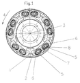
- the hub part 1 in the area of its outer circumference by a Flange formed, the absorber masses 2 in the axial direction on both sides are neighboring.
- the absorber masses 2 are in the hub part 1 mounted on bolts 5 on the of the respective curved tracks 6 opposite sides guided radially through a guide track 7 and are supported in the radial direction.
Landscapes
- Engineering & Computer Science (AREA)
- General Engineering & Computer Science (AREA)
- Physics & Mathematics (AREA)
- Acoustics & Sound (AREA)
- Aviation & Aerospace Engineering (AREA)
- Mechanical Engineering (AREA)
- Mechanical Operated Clutches (AREA)
Claims (13)
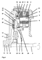
- Vilebrequin d'une machine motrice ou d'une outil-machine activée périodiquement avec un amortisseur fixé solidement dessus qui comprend au moins une partie de moyeu (1) pouvant tourner autour d'un axe de rotation ainsi que plusieurs masses d'amortissement (2) qui peuvent pivoter successivement autour d'axes de pivotement du mouvement de rotation (4) situés à distance de l'axe de rotation (3), le centre de gravité de chaque masse d'amortissement (2) étant déplacé en fonction du nombre de tours de telle manière que les axes de pivotement (5) des masses d'amortissement (2) sont guidés en fonction du nombre de tours de manière déplaçable radialement, caractérisé en ce que l'amortisseur est agencé directement sur une roue volante (18), reliée au vilebrequin (13), de la machine motrice ou de l'outil-machine et en ce que l'amortisseur présente une butée (29) pour un ressort de pression (26) d'un dispositif d'accouplement.
- Vilebrequin selon la revendication 1, caractérisé en ce qu'entre la roue volante (18) et l'amortisseur est disposé un disque d'embrayage (24) avec plateau de pression d'embrayage (23) et plateau de fermeture d'embrayage (20).
- Vilebrequin selon l'une des revendications 1 ou 2, caractérisé en ce que l'amortisseur présente des boulons de guidage (22) pour le plateau de pression d'embrayage (23).
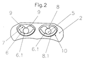
- Vilebrequin selon l'une des revendications 1 à 3, caractérisé en ce que chaque masse d'amortissement (2) est logée dans la partie de moyeu (1) par deux boulons (5) situès à distance dans le sens circonférentiel, s'étendant parallèlement à l'axe de rotation (3) et dans lequel les boulons (5) peuvent se déplacer en roulant sur des chemins incurvés (6) qui ont dans la zone de la partie de moyeu (1) un profil ouvert en forme de U dans le sens de l'axe de rotation (3) et dans la zone des masses d'amortissement (2) un profil ouvert en forme de U dans le sens inverse et en ce que les boulons (5) sont guidés sur les côtés opposés aux chemins incurvés respectifs (6) grâce à une coulisse (7).
- Vilebrequin selon la revendication 4, caractérisé en ce que la coulisse (7) est composée d'une couche d'amortissement (8) en matière polymère.
- Vilebrequin selon la revendication 4 ou 5, caractérisé en ce que la couche d'amortissement (8) est composée d'une matière élastomère.
- Vilebrequin selon l'une des revendications 4 à 6, caractérisé en ce que la couche d'amortissement (8) se termine dans le sens circonférentiel des deux côtés dans des surfaces de butée (9), par lesquelles la mobilité circonférentielle des boulons (5) est limitée à une valeur fixe.
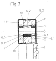
- Vilebrequin selon l'une des revendications 4 à 7, caractérisé en ce que les chemins incurvés (6) forment une partie constitutive des pièces intercalaires (6.1/6.2).
- Vilebrequin selon la revendication 8, caractérisé en ce que les pièces intercalaires (6.1 / 6.2) et les couches d'amortissement (8) forment une partie constitutive des pièces intercalaires qui sont prises sans pouvoir être déplacées dans les évidements (10) de la partie de moyeu (1) et des masses d'amortissement (2).
- Vilebrequin selon la revendication 9, caractérisé en ce que la matière formant les couches d'amortissement (8) est reliée après i'insertion des pièces intercalaires (6.1) dans les évidements (10) par moulage direct et durcissement avec les évidements (10) et les pièces intercalaires (6.1).
- Vilebrequin selon l'une des revendications 4 à 10, caractérisé en ce qu'un espace libre est présent entre la masse d'amortissement (2) resp. le moyeu (1) et les pièces intercalaires (6.1 / 6.2) et en ce que l'espace libre est rempli de la matière de la couche d'amortissement et forme une couche de compensation de tolérance (8.1, 8.2).
- Vilebrequin selon la revendication 11, caractérisé en ce que la couche de compensation de tolérance (8.1, 8.2) et la couche d'amortissement sont conçues en se mêlant l'une à l'autre pour ne former qu'une seule pièce.
- Vilebrequin selon l'une des revendications 8 à 12, caractérisé en ce que les pièces intercalaires (6.1) sont produites par extrusion.
Applications Claiming Priority (2)
| Application Number | Priority Date | Filing Date | Title |
|---|---|---|---|
| DE1996115890 DE19615890C1 (de) | 1996-04-22 | 1996-04-22 | Kurbelwelle |
| DE19615890 | 1996-04-22 |
Publications (2)
| Publication Number | Publication Date |
|---|---|
| EP0803659A1 EP0803659A1 (fr) | 1997-10-29 |
| EP0803659B1 true EP0803659B1 (fr) | 2001-12-19 |
Family
ID=7792018
Family Applications (1)
| Application Number | Title | Priority Date | Filing Date |
|---|---|---|---|
| EP19970102611 Expired - Lifetime EP0803659B1 (fr) | 1996-04-22 | 1997-02-19 | Vilebrequin avec amortissuer de vibrations |
Country Status (2)
| Country | Link |
|---|---|
| EP (1) | EP0803659B1 (fr) |
| DE (1) | DE19615890C1 (fr) |
Cited By (3)
| Publication number | Priority date | Publication date | Assignee | Title |
|---|---|---|---|---|
| CN102762887A (zh) * | 2009-12-21 | 2012-10-31 | 舍弗勒技术股份两合公司 | 离心力摆装置 |
| CN104937306A (zh) * | 2012-12-22 | 2015-09-23 | 奥迪股份公司 | 离心摆式减振设备以及机动车的动力传动系 |
| EP2697530B2 (fr) † | 2011-04-11 | 2018-05-09 | Schaeffler Technologies AG & Co. KG | Ensemble embrayage |
Families Citing this family (19)
| Publication number | Priority date | Publication date | Assignee | Title |
|---|---|---|---|---|
| DE19709092C1 (de) * | 1997-03-06 | 1998-05-14 | Freudenberg Carl Fa | Kupplung |
| DE19831157B4 (de) * | 1998-07-11 | 2005-04-14 | Carl Freudenberg Kg | Drehzahladaptiver Schwingungstilger |
| DE19831153A1 (de) * | 1998-07-11 | 2000-01-13 | Freudenberg Carl Fa | Drehzahladaptiver Schwingungstilger |
| DE19911564B4 (de) * | 1999-03-16 | 2009-03-19 | Zf Sachs Ag | Schwingungsdämpfungsvorrichtung |
| DE19951577C2 (de) * | 1999-10-27 | 2002-06-27 | Freudenberg Carl Kg | Zweimassen-Schwungrad |
| DE10037680A1 (de) | 2000-08-02 | 2002-02-14 | Freudenberg Carl Kg | Schwungrad mit drehzahladaptivem Schwingungstilger |
| DE10037689B4 (de) * | 2000-08-02 | 2008-01-03 | Carl Freudenberg Kg | Kurbelwelle mit einer Schwungmasse |
| DE10054561B4 (de) * | 2000-10-31 | 2004-09-02 | Festo Ag & Co. | Ventilgesteuerte fluidische Aktoranordnung |
| DE10225299A1 (de) * | 2002-06-07 | 2003-12-18 | Bayerische Motoren Werke Ag | Schwenkmotorgetriebe eines Kraftfahrzeugstabilisators |
| EP1744074A3 (fr) * | 2005-07-11 | 2008-10-01 | LuK Lamellen und Kupplungsbau Beteiligungs KG | Dispositif de transmission de couple |
| DE102008053377B4 (de) * | 2007-11-22 | 2018-09-20 | Schaeffler Technologies AG & Co. KG | Rupftilger |
| JP5362007B2 (ja) * | 2008-08-21 | 2013-12-11 | シェフラー テクノロジーズ アクチエンゲゼルシャフト ウント コンパニー コマンディートゲゼルシャフト | 回動振動吸振器 |
| DE102010009473A1 (de) * | 2009-03-16 | 2010-09-23 | Luk Lamellen Und Kupplungsbau Beteiligungs Kg | Fliehkraftpendel |
| WO2011110153A1 (fr) * | 2010-03-11 | 2011-09-15 | Schaeffler Technologies Gmbh & Co. Kg | Dispositif d'amortissement d'oscillation de torsion |
| DE102011085905A1 (de) | 2010-12-02 | 2012-06-06 | Schaeffler Technologies Gmbh & Co. Kg | Drehschwingungstilgervorrichtung und Drehmomentübertragungsvorrichtung für ein Kraftfahrzeug |
| DE112011104590B4 (de) * | 2010-12-24 | 2022-01-05 | Schaeffler Technologies AG & Co. KG | Fliehkraftpendeleinrichtung |
| WO2012130202A1 (fr) * | 2011-03-31 | 2012-10-04 | Schaeffler Technologies AG & Co. KG | Dispositif pendulaire à force centrifuge |
| DE102012221265B4 (de) * | 2011-12-07 | 2017-05-24 | Schaeffler Technologies AG & Co. KG | Fliehkraftpendel mit Dämpfer |
| DE102014214634A1 (de) * | 2014-07-25 | 2016-01-28 | Schaeffler Technologies AG & Co. KG | Rotationsbaugruppe für eine Kupplung und/oder Dämpfereinrichtung sowie Drehmomentübertragungseinrichtung |
Family Cites Families (8)
| Publication number | Priority date | Publication date | Assignee | Title |
|---|---|---|---|---|
| GB598811A (en) * | 1945-09-11 | 1948-02-26 | Lemuel John Stone | Improvements in or relating to vibration-damping devices |
| CH163966A (de) * | 1932-06-08 | 1933-09-15 | Sulzer Ag | Vorrichtung auf Wellen zur Verminderung von torsionsschwingungen. |
| US2029796A (en) * | 1933-11-29 | 1936-02-04 | Salomon Francois Marie Bernard | Vibration dampener |
| US2451513A (en) * | 1938-08-17 | 1948-10-19 | Salomon Francois Marie Bernard | Oscillation reducing device |
| US2448973A (en) * | 1945-02-22 | 1948-09-07 | Fairchild Engine & Airplane | Dynamic damper support |
| US2454720A (en) * | 1947-01-31 | 1948-11-23 | United Aircraft Corp | Crankshaft torsional vibration damper |
| US4674356A (en) * | 1985-05-01 | 1987-06-23 | Kilgore Ronald B | Dynamic rotational counterbalance structure |
| JP2606292Y2 (ja) * | 1993-08-18 | 2000-10-10 | ヴァレオユニシアトランスミッション株式会社 | フライホイール |
-
1996
- 1996-04-22 DE DE1996115890 patent/DE19615890C1/de not_active Expired - Fee Related
-
1997
- 1997-02-19 EP EP19970102611 patent/EP0803659B1/fr not_active Expired - Lifetime
Cited By (5)
| Publication number | Priority date | Publication date | Assignee | Title |
|---|---|---|---|---|
| CN102762887A (zh) * | 2009-12-21 | 2012-10-31 | 舍弗勒技术股份两合公司 | 离心力摆装置 |
| CN102762887B (zh) * | 2009-12-21 | 2016-07-20 | 舍弗勒技术股份两合公司 | 离心力摆装置 |
| EP2697530B2 (fr) † | 2011-04-11 | 2018-05-09 | Schaeffler Technologies AG & Co. KG | Ensemble embrayage |
| CN104937306A (zh) * | 2012-12-22 | 2015-09-23 | 奥迪股份公司 | 离心摆式减振设备以及机动车的动力传动系 |
| CN104937306B (zh) * | 2012-12-22 | 2016-10-12 | 奥迪股份公司 | 离心摆式减振设备以及机动车的动力传动系 |
Also Published As
| Publication number | Publication date |
|---|---|
| DE19615890C1 (de) | 1998-01-02 |
| EP0803659A1 (fr) | 1997-10-29 |
Similar Documents
| Publication | Publication Date | Title |
|---|---|---|
| EP0803659B1 (fr) | Vilebrequin avec amortissuer de vibrations | |
| EP0789163B1 (fr) | Amortisseur adapté de vélocité rotative | |
| DE10224874B4 (de) | Drehmomentübertragungseinrichtung | |
| DE10059101B4 (de) | Antriebssystem | |
| DE3800566C2 (de) | Schwungrad | |
| EP0304474B1 (fr) | Accouplement elastique | |
| DE19804227B4 (de) | Überbrückungskupplung mit einer Ausgleichsschwungmasse am Torsionsschwingungsdämpfer | |
| DE19831158A1 (de) | Schwungrad | |
| DE19734322B4 (de) | Torsionsschwingungsdämpfer mit Wälzkörpern als Koppelelemente | |
| EP2000699B1 (fr) | Amortisseur d'oscillations de torsions ou découpleur doté de fils de fer enroulés dans un disque d'entraînement | |
| DE19652730A1 (de) | Triebscheibe | |
| DE3702842A1 (de) | Schwungradanordnung einer kupplung | |
| DE4225304A1 (de) | Scheibenfoermiges bauteil | |
| EP1795780A1 (fr) | Amortisseur de vibrations torsionelles pour convertisseur hydrodynamique | |
| EP0828090A2 (fr) | Amortisseur adaptatif de vélocité rotative | |
| DE602004001215T2 (de) | Drehmomentübertragungsvorrichtung mit einem dämpfenden zweimassenschwungrad, für ein kraftfahrzeug | |
| DE3901471C2 (de) | Drehschwingungsdämpfer | |
| WO2016023795A1 (fr) | Système d'amortissement de vibrations de torsion, en particulier module amortisseur | |
| DE4013101C2 (de) | Drehschwingungsdämpfer mit dynamischem Schwingungsdämpfer, insbesondere für Kraftfahrzeuge | |
| WO2009068453A2 (fr) | Dispositif d'accouplement hydrodynamique | |
| EP1866538B1 (fr) | Transmission mixte | |
| WO2017028858A1 (fr) | Pendule à force centrifuge et convertisseur de couple hydrodynamique équipé d'un pendule à force centrifuge | |
| DE4303303C1 (de) | Antriebsstrang eines Kraftfahrzeugs | |
| DE19647974A1 (de) | Reibungskupplung | |
| DE10018955B4 (de) | Antriebssystem |
Legal Events
| Date | Code | Title | Description |
|---|---|---|---|
| PUAI | Public reference made under article 153(3) epc to a published international application that has entered the european phase |
Free format text: ORIGINAL CODE: 0009012 |
|
| 17P | Request for examination filed |
Effective date: 19970721 |
|
| AK | Designated contracting states |
Kind code of ref document: A1 Designated state(s): FR GB IT SE |
|
| 17Q | First examination report despatched |
Effective date: 19990916 |
|
| GRAG | Despatch of communication of intention to grant |
Free format text: ORIGINAL CODE: EPIDOS AGRA |
|
| GRAG | Despatch of communication of intention to grant |
Free format text: ORIGINAL CODE: EPIDOS AGRA |
|
| GRAH | Despatch of communication of intention to grant a patent |
Free format text: ORIGINAL CODE: EPIDOS IGRA |
|
| GRAH | Despatch of communication of intention to grant a patent |
Free format text: ORIGINAL CODE: EPIDOS IGRA |
|
| GRAA | (expected) grant |
Free format text: ORIGINAL CODE: 0009210 |
|
| AK | Designated contracting states |
Kind code of ref document: B1 Designated state(s): FR GB IT SE |
|
| REG | Reference to a national code |
Ref country code: GB Ref legal event code: IF02 |
|
| RAP2 | Party data changed (patent owner data changed or rights of a patent transferred) |
Owner name: CARL FREUDENBERG KG |
|
| GBT | Gb: translation of ep patent filed (gb section 77(6)(a)/1977) |
Effective date: 20020314 |
|
| PLBE | No opposition filed within time limit |
Free format text: ORIGINAL CODE: 0009261 |
|
| STAA | Information on the status of an ep patent application or granted ep patent |
Free format text: STATUS: NO OPPOSITION FILED WITHIN TIME LIMIT |
|
| 26N | No opposition filed | ||
| PGFP | Annual fee paid to national office [announced via postgrant information from national office to epo] |
Ref country code: SE Payment date: 20030205 Year of fee payment: 7 |
|
| PGFP | Annual fee paid to national office [announced via postgrant information from national office to epo] |
Ref country code: FR Payment date: 20030210 Year of fee payment: 7 |
|
| PGFP | Annual fee paid to national office [announced via postgrant information from national office to epo] |
Ref country code: GB Payment date: 20030219 Year of fee payment: 7 |
|
| PG25 | Lapsed in a contracting state [announced via postgrant information from national office to epo] |
Ref country code: GB Free format text: LAPSE BECAUSE OF NON-PAYMENT OF DUE FEES Effective date: 20040219 |
|
| PG25 | Lapsed in a contracting state [announced via postgrant information from national office to epo] |
Ref country code: SE Free format text: LAPSE BECAUSE OF NON-PAYMENT OF DUE FEES Effective date: 20040220 |
|
| EUG | Se: european patent has lapsed | ||
| GBPC | Gb: european patent ceased through non-payment of renewal fee |
Effective date: 20040219 |
|
| PG25 | Lapsed in a contracting state [announced via postgrant information from national office to epo] |
Ref country code: FR Free format text: LAPSE BECAUSE OF NON-PAYMENT OF DUE FEES Effective date: 20041029 |
|
| REG | Reference to a national code |
Ref country code: FR Ref legal event code: ST |
|
| PG25 | Lapsed in a contracting state [announced via postgrant information from national office to epo] |
Ref country code: IT Free format text: LAPSE BECAUSE OF NON-PAYMENT OF DUE FEES Effective date: 20050219 |