EP0803628B1 - Seitenblende mit Einklemmschutzsensor und Fensterheberantriebsvorrichtung unter Verwendung derselben - Google Patents
Seitenblende mit Einklemmschutzsensor und Fensterheberantriebsvorrichtung unter Verwendung derselben Download PDFInfo
- Publication number
- EP0803628B1 EP0803628B1 EP97106638A EP97106638A EP0803628B1 EP 0803628 B1 EP0803628 B1 EP 0803628B1 EP 97106638 A EP97106638 A EP 97106638A EP 97106638 A EP97106638 A EP 97106638A EP 0803628 B1 EP0803628 B1 EP 0803628B1
- Authority
- EP
- European Patent Office
- Prior art keywords
- window
- side visor
- window frame
- sensing
- conducting members
- Prior art date
- Legal status (The legal status is an assumption and is not a legal conclusion. Google has not performed a legal analysis and makes no representation as to the accuracy of the status listed.)
- Expired - Lifetime
Links
- 238000006073 displacement reaction Methods 0.000 claims description 30
- 239000013013 elastic material Substances 0.000 claims description 9
- 239000004698 Polyethylene Substances 0.000 claims description 7
- -1 polyethylene Polymers 0.000 claims description 7
- 229920000573 polyethylene Polymers 0.000 claims description 7
- 229920002635 polyurethane Polymers 0.000 claims description 7
- 239000004814 polyurethane Substances 0.000 claims description 7
- 238000001514 detection method Methods 0.000 claims description 5
- 239000005357 flat glass Substances 0.000 description 32
- 230000009471 action Effects 0.000 description 7
- 230000007246 mechanism Effects 0.000 description 7
- 230000004048 modification Effects 0.000 description 6
- 238000012986 modification Methods 0.000 description 6
- 239000011347 resin Substances 0.000 description 6
- 229920005989 resin Polymers 0.000 description 6
- 229920001971 elastomer Polymers 0.000 description 5
- 238000006243 chemical reaction Methods 0.000 description 3
- 238000007789 sealing Methods 0.000 description 3
- 229910000906 Bronze Inorganic materials 0.000 description 2
- OAICVXFJPJFONN-UHFFFAOYSA-N Phosphorus Chemical compound [P] OAICVXFJPJFONN-UHFFFAOYSA-N 0.000 description 2
- 238000005299 abrasion Methods 0.000 description 2
- 239000010974 bronze Substances 0.000 description 2
- KUNSUQLRTQLHQQ-UHFFFAOYSA-N copper tin Chemical compound [Cu].[Sn] KUNSUQLRTQLHQQ-UHFFFAOYSA-N 0.000 description 2
- 230000007423 decrease Effects 0.000 description 2
- 230000007257 malfunction Effects 0.000 description 2
- 229910001220 stainless steel Inorganic materials 0.000 description 2
- 239000010935 stainless steel Substances 0.000 description 2
- XLYOFNOQVPJJNP-UHFFFAOYSA-N water Substances O XLYOFNOQVPJJNP-UHFFFAOYSA-N 0.000 description 2
- 239000000853 adhesive Substances 0.000 description 1
- 230000001070 adhesive effect Effects 0.000 description 1
- 239000002390 adhesive tape Substances 0.000 description 1
- 230000008859 change Effects 0.000 description 1
- 244000145845 chattering Species 0.000 description 1
- 238000010586 diagram Methods 0.000 description 1
- 238000009429 electrical wiring Methods 0.000 description 1
- 230000007274 generation of a signal involved in cell-cell signaling Effects 0.000 description 1
- 239000011810 insulating material Substances 0.000 description 1
- 238000004519 manufacturing process Methods 0.000 description 1
- 238000002844 melting Methods 0.000 description 1
- 230000008018 melting Effects 0.000 description 1
- 239000002184 metal Substances 0.000 description 1
- 238000000034 method Methods 0.000 description 1
- 238000000465 moulding Methods 0.000 description 1
- 230000002093 peripheral effect Effects 0.000 description 1
- 238000003825 pressing Methods 0.000 description 1
- 230000008569 process Effects 0.000 description 1
- 230000001681 protective effect Effects 0.000 description 1
- 238000009331 sowing Methods 0.000 description 1
- 239000000126 substance Substances 0.000 description 1
- 238000003466 welding Methods 0.000 description 1
Images


Classifications
-
- B—PERFORMING OPERATIONS; TRANSPORTING
- B60—VEHICLES IN GENERAL
- B60J—WINDOWS, WINDSCREENS, NON-FIXED ROOFS, DOORS, OR SIMILAR DEVICES FOR VEHICLES; REMOVABLE EXTERNAL PROTECTIVE COVERINGS SPECIALLY ADAPTED FOR VEHICLES
- B60J10/00—Sealing arrangements
-
- E—FIXED CONSTRUCTIONS
- E05—LOCKS; KEYS; WINDOW OR DOOR FITTINGS; SAFES
- E05F—DEVICES FOR MOVING WINGS INTO OPEN OR CLOSED POSITION; CHECKS FOR WINGS; WING FITTINGS NOT OTHERWISE PROVIDED FOR, CONCERNED WITH THE FUNCTIONING OF THE WING
- E05F15/00—Power-operated mechanisms for wings
- E05F15/40—Safety devices, e.g. detection of obstructions or end positions
- E05F15/42—Detection using safety edges
- E05F15/44—Detection using safety edges responsive to changes in electrical conductivity
- E05F15/443—Detection using safety edges responsive to changes in electrical conductivity specially adapted for vehicle windows or roofs
-
- E—FIXED CONSTRUCTIONS
- E05—LOCKS; KEYS; WINDOW OR DOOR FITTINGS; SAFES
- E05Y—INDEXING SCHEME ASSOCIATED WITH SUBCLASSES E05D AND E05F, RELATING TO CONSTRUCTION ELEMENTS, ELECTRIC CONTROL, POWER SUPPLY, POWER SIGNAL OR TRANSMISSION, USER INTERFACES, MOUNTING OR COUPLING, DETAILS, ACCESSORIES, AUXILIARY OPERATIONS NOT OTHERWISE PROVIDED FOR, APPLICATION THEREOF
- E05Y2900/00—Application of doors, windows, wings or fittings thereof
- E05Y2900/50—Application of doors, windows, wings or fittings thereof for vehicles
- E05Y2900/53—Type of wing
- E05Y2900/55—Windows
-
- H—ELECTRICITY
- H01—ELECTRIC ELEMENTS
- H01H—ELECTRIC SWITCHES; RELAYS; SELECTORS; EMERGENCY PROTECTIVE DEVICES
- H01H2300/00—Orthogonal indexing scheme relating to electric switches, relays, selectors or emergency protective devices covered by H01H
- H01H2300/01—Application power window
-
- H—ELECTRICITY
- H01—ELECTRIC ELEMENTS
- H01H—ELECTRIC SWITCHES; RELAYS; SELECTORS; EMERGENCY PROTECTIVE DEVICES
- H01H3/00—Mechanisms for operating contacts
- H01H3/02—Operating parts, i.e. for operating driving mechanism by a mechanical force external to the switch
- H01H3/14—Operating parts, i.e. for operating driving mechanism by a mechanical force external to the switch adapted for operation by a part of the human body other than the hand, e.g. by foot
- H01H3/141—Cushion or mat switches
- H01H3/142—Cushion or mat switches of the elongated strip type
Definitions
- the present invention relates to a side visor and a power window apparatus for vehicles using the same for an anti-pinching mechanism.
- a power window apparatus having an anti-pinching mechanism disclosed in Japanese Utility Model Laid-Open No. Sho 64-53389 for instance, is provided with a sensing member, such as a pressure-sensitive tube sensor for sensing an external force, along the inside periphery of a window frame.
- a sensing member such as a pressure-sensitive tube sensor for sensing an external force, along the inside periphery of a window frame. This sensing member senses an external force applied when a foreign object is caught between a window glass and the window frame, to thereby stop a driving motor for moving the window glass up and down.
- a conventional sensing member as disclosed in Japanese Patent Laid-Open No. Hei 6-260054 for instance, has a predetermined space with band-like electrodes of conducting rubber formed face to face and with elastic members of insulating rubber arranged on both ends in the direction of width intersecting at right angles the longitudinal direction of the band-like electrodes. A specific voltage is applied between the band-like electrodes to sense the external force with the voltage thus applied between the band-like electrodes.
- An external force F acting on the sensing member 4 acts on the point of action f at a contact point between the weatherstrip 8 and the foreign object 7; therefore the larger the size h of the outside dimensions of the side visor 5 in a direction in which the window glass 2 is opened and closed, the more the point of action f moves toward the vehicle interior.
- the point of action f will be positioned out of the sensible range of the sensing member 4. In this state the sensing member 4 can not sense the external force, causing the occurrence of the above-described trouble.
- the edge portion 5a of the side visor 5 is positioned on the closed side of the window glass 2 off the location of the sensing member 4, the foreign object 7 will be caught between the window glass 2 and the side visor 5 before it contacts the sensing member 4 particularly when the foreign object 7 comes in from above toward the vehicle interior as shown by two-dot chain line in Fig. 32, thus resulting in the aforesaid trouble.
- a sensing member for sensing the external force is provided on a side visor body.
- this sensing member is disposed in the joining part of the side visor between a window frame and the side visor.
- an insulating holding member for holding a pair of conducting members to define a space may be made of a porous elastic material such as polyurethane polyethylene.
- a closing operation stopping member is provided.
- This stopping member will stop movement of a window body toward closing when an external force acting on a side visor which is sensed by the sensing member exceeds a predetermined value.
- the sensing member thus senses the external force acting on the side visor to thereby detect a foreign object being pinched. It is, therefore, possible to prevent such a trouble that the upward movement of the window body will not be stopped in case the foreign object is pinched between the window body and the side visor.
- the sensing member is disposed in the joining part between the side visor and the window frame. Therefore, even if the part of intersection between the sensing member and the line of action of the external force acting on the side visor is a dead zone where the external force can not be sensed, the external force can be sensed by a reaction from the vicinity of the part of intersection between the window frame and the line of action of the external force.
- the sensing member may be disposed within a cover member covering the joining part from above.
- the sensing member may be comprised of a holding member for holding a pair of conducting members, and a displacement member which makes a relative displacement with respect to the pair of conducting members. Furthermore, the displacement member may be provided with a displacement restricting member for restricting the displacement of the displacement member in a direction which intersects the direction of movement of the window body.
- an insulating holding member for holding a pair of conducting members to form a space may be produced of a porous elastic material.
- the porous elastic material be polyurethane or polyethylene.
- movement of a window body toward closing may be stopped when an external force sensed by a sensing member exceeds a predetermined value and when a detected value of a driving load of the window body driving device detected by a load detecting member exceeds a predetermined value.
- movement of a window body toward closing may be stopped when an external force sensed by at least one of a first sensing member for sensing an external force acting on a side visor and a second sensing member for sensing an external force acting on a window frame exceeds a predetermined value and also when a detected value of the driving load of a window body driving device detected by a load detecting member exceeds a predetermined value.
- the second sensing member may be inserted in a weatherstrip.
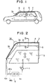
- reference numeral 1 denotes a driving motor (a window body driving member) for driving to move up and down a window glass (a window body) 2 which opens and closes a window opening 3a
- reference numeral 3 denotes a window frame forming the window opening 3a.
- a side visor (side visor body) 5 made of resin for shading the upper periphery of the window opening 3a is mounted.
- one cord switch (sensing member) 4 for sensing the external force acting on the side visor 5 is arranged through from the front portion 3b to the upper portion 3c of the window frame 3.
- an elastic member 9 made of an elastic material for absorbing irregularities of these members 3 and 5 is attached by an adhesive to these members 3 and 5.
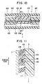
- a recess section 51 for mounting the cord switch 4 therein is formed in a part corresponding to the front portion 3b through to the upper portion 3c of the window frame 3.
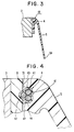
- the cord switch 4 is shown in Figs. 5A through 5C, in which in Fig. 5B shows the section along line C-O1-C in Fig. 5A.
- Numeral 41 designates an elastically deformable covered tube made of an insulating material such as a resin.
- this covered tube 41 are arranged three first to third elastically deformable conducting members 42 to 44 extending in the longitudinal direction. These conducting members 42 to 44 have nearly an equal circular sectional form.
- the wire diameter of the conducting members 42 to 44 is about 0.5 to 1.0 mm.
- These conducting members 42 to 44 are arranged in a triangular form (01-02-03) in such a manner that one conducting member will face the other two conducting members.
- the conducting members 42 to 44 are formed of a high fatigue-limit metal such as stainless steel, phosphor bronze, etc.
- first and second insulating members 47 and 48 are securely attached, covering a part of the circumferential side face of the conducting members 43 and 44. Furthermore, the first and second insulating members 47 and 48, as shown in Fig. 5C, have a predetermined spacing L in the longitudinal direction of the covered tube 1, and are arranged such that one insulating member will be positioned between adjacent ones of the other insulating members.
- the insulating members 47 and 48 are formed of resin, and the non-adhering surfaces 47a and 48a of the insulating members 47 and 48 (in the insulating member 47, the surface facing the first and third conducting members 42 and 44; and in the insulating member 48, the surface facing the first and second conducting members 42 and 43) slidably contacts the conducting member which faces the surface.
- Electrical wirings 42a to 44a are connected to the ends in the longitudinal direction of the conducting members 42 to 44, respectively. These wirings 42a to 44a, as shown in Fig. 1, are connected to a control device 6 and a specific voltage is applied between the first conducting member 42 and the second conducting member 43 and between the first conducting member 42 and the third conducting member 44.
- a control device 6 detects that a foreign object is pinched between the window frame 3 and the window glass 2, giving a signal 6a to the driving motor 1 to stop the opening and closing operation of the window glass 2.
- a foreign object In an automotive vehicle door having the side visor, a foreign object, if pinched, will contact the side visor 5 and the window glass 2. That is, in the event the foreign object is pinched in the automotive door having the side visor 5, the foreign object contacts at least both of the lowermost edge portion 5a of the side visor 5 and the top end portion 2a of the window glass 2 (Fig. 32).
- the cord switch 4 detects the pinching of the foreign object by sensing the external force F acting on the side visor 5, and therefore it is possible to prevent the trouble that-if the foreign object is pinched between the window glass 2 and the side visor 5, the upward and downward movement of the window glass 2 will not stop.
- a reaction against the external force F acting on the side visor 5 is generated not only at the intersection between the line of action of the external force acting on the side visor 5 and the window frame 3 but in the vicinity of the intersection.
- the cord switch 4 is located in the joining part IV between the window frame 3 and the side visor 5. Therefore, if the external force F acts on a specific part of the side visor 5 for instance, there will never occur such a trouble that the external force F acts only on a specific part of the cord switch 4 corresponding thereto.
- the conducting members 42 to 44 are located in the dead zones which will not be deflected (the current will not flow) when the specific part of the cord switch 4 receives the external force F like the immediately upper part of the insulating members 47 and 48, the conducting members 42 to 44 in the vicinity of the insulating members 47, 48 will be deflected with a reaction from the window frame 3, becoming ready for energizing. Therefore, it is possible to reliably sense the external force irrespective of the part of action of the external force on the side visor 5.
- the foreign object if pinched, contacts the edge portion 5a of the side visor 5 as described above. It is, therefore, possible to dispose the cord switch 4 on the edge portion 5a of the side visor 5.
- the edge portion 5a of the side visor 5 is located in a position where the edge portion 5a easily contacts a driver or a passenger, regardless of the pinching of a foreign object, when he gets on or off the automobile. Therefore in arranging the cord switch 4 on the edge portion 5a of the side visor 5, it is necessary to take due consideration of the abrasion resistance of the covered tube 41.
- the cord switch 4 is mounted in the joining part IV between the window frame 3 and the side visor 5, the driver or passenger will not touch the covered tube 41 when getting on or off the automobile. Therefore no consideration of the abrasion resistance of the covered tube 41 is needed.
- This design not only improves durability of the cord switch 4 but improves durability of a power window apparatus having the anti-pinching mechanism.
- cord switch 4 used in the present embodiment is not limited to the above-described one and may be another type of cord switch 4' shown in Fig. 6.
- the elastic member 9 interposed between the side visor 5 and the window frame 3 may be dispensed with.
- the side visor 5 is a molding of an insulating resin.
- the insulating members 47 and 48 of the cord switch 4 is molded integrally with the side visor 5 so that the covered tube 41 in the first embodiment is not used.
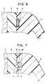
- reference numerals 401 and 402 denote first and second conducting members extended along the window frame 3 and disposed face to face across a predetermined space. These conducting members 401 and 402 are held by a holding member 403 of resin joined to the window frame 3.
- the conducting members 401 and 402 are displaceable (slidable) in the longitudinal direction of the conducting members 401 and 402 with respect to the holding member 403, have a circular cross section, and are made of stainless steel or phosphor bronze.
- Reference numeral 404 designates a displaceable member made of resin which can be displaced with respect to the conducting members 401 and 402.
- This displaceable member 404 is provided with a through hole 405 through which the conducting members 401 and 402 are inserted.
- the holding member 403 and the displaceable member 404 are arranged alternately along the contour of the window frame 3.
- a triangular projection 404a protruding toward closing the window glass 2 is formed on the side of second conducting member 402 of the through hole 405, while a smooth flat surface is formed on the side of first conducting member 401.
- the holding member 403 is connected to the window frame 3 and the displacement member 404 is connected to the joining part IV of the side visor 5.
- the sectional form of the through hole 405 is oblong as shown in Fig. 9 so that the direction of long diameter will agree with the direction of operation (movement) of the window glass 2, and that the short diameter of the through hole 405 will nearly coincides with the diameter of the through hole 405.
- the oblong configuration of the through hole 405, two conducting members 401, and the window frame 3 constitute the displacement restricting member for restricting displacement of the displacement member 404 in a direction in which the displacement member 404 intersects the direction of movement of the window glass 2.
- Reference numeral 406 denotes a sealing member made of an elastic material, such as rubber, for preventing entrance of foreign substances, for example rain water, into the cord switch 4.
- the side visor 5 moves toward closing (upwardly) as shown in Figs. 10 and 11, thus moving the displacement member 404 upwardly.
- the external force F concentratedly acts on the conducting member 402 through the projection 404a, to deflect the second conducting member 402 into contact with the first conducting member 401, thereby detecting the external force F.
- the displacement of the displacement member 404 in the direction intersecting the direction of window glass operation is restricted by the oblong hole configuration of the through hole 405. Therefore there will not occur such an error as detecting an external force of wind for example exerted in a direction intersecting the direction of operation of the window glass 2. Only the external force F resulting from the pinching of a foreign object can be detected.
- both the conducting members 401 and 402 are movable in the longitudinal direction of both the conducting members 401 and 402 in relation to the holding member 403, a difference in the curvature radius of both the conducting members 401 and 402 can be absorbed if the cord switch 4 is located in the bent section 3d (Fig. 2) of the window frame 3. Therefore, it is possible to prevent the trouble that both the conducting members 401 and 402 contact notwithstanding the external force F is not exerted to the bent section 3d.
- the control device 6 generates a signal 6a at time t1 when the external force F (F1 in Fig. 12) is detected with the contact of both the conducting members 401 and 402, the window glass 2 will stop or reverse at time t2 with a time lag caused by the moment of inertia of the driving motor 1 and the inertia force of the window glass 2 after the detection of the external force F (this phenomenon is called the time lag).
- the rigidity of the cord switch 4' increases after both the conducting members contact, resulting in a sudden increase in the external force F produced as indicated by a dot-and-chain line in Fig. 12.
- both the conducting members 401 and 402 can be displaced or deformed even after the contact of the conducting member 402 with the first conducting member 401, and therefore it becomes possible to prevent the external force F from excessively increasing during the period of time lag so that it may change as indicated by a full line in Fig. 12.
- the holding member 403 is connected to the window frame 3 and the displacement member 404 is connected to the joining part IV of the side visor 5. It should be noted that the holding member 403 may be connected to the joining part IV of the side visor 5 and the displacement member 404, to the window frame 3.
- the cord switch 4 including both the conducting members 401 and 402, the holding member 403, and the displacement member 404 is disposed in such a manner that its entire part is covered with the sealing member 406, as shown in Figs. 13 and 14 the sealing member 406 is provided only in the part of contact between the holding member 403 and the displacement member 404.
- Figs. 13 and 14 indicate the cord switch 4 on which the external force F is acting.
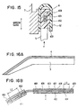
- a cover section 5b is formed integrally with the side visor 5 to prevent the entry of rain water directly into the cord switch 4.
- the cover section 5b is formed integral with the side visor 5, in the present embodiment shown in Fig. 15 and Figs. 16A and 16B, the side visor 5 is slidably held in the up-and-down direction (in the direction in which the window glass 2 is opened and closed), and at the same time a cover member 52 is provided separately from the side visor 5, having a U-bent section and covering as if holding the joining part of the side visor 5 from above.
- the inner wall of the cover member 52 serves also as a displacement restricting member (a guide wall) which allows the side visor 5 to slide only in the up-and-down direction.
- the cord switch 4 is mounted in the cover member 52 and the holding member 403 is connected to the inner wall of the cover member 52.
- the projection is not needed to be mounted in all the displacement member 404, and may be dispensed with in the region of the window frame 3 where the external force F caused by the pinching of a foreign object increases.
- the external force F is uniformly distributed to the second conducting member 402. Therefore the external force F necessary for contacting the conducting members 401 and 402 increases greater than that in the displacement member 404 provided with the projection.
- the sizes L1 and L2 of the displacement member 404 may be changed in the region parallel with the longitudinal direction of both the conducting members 401 and 402 in accordance with the region of the window frame 3.
- the size L1 in the upper portion 3c is smaller than the size L2 in the front portion 3b.
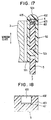
- a cord switch 4 is inserted in a bent section 52a of the cover member 52 as shown in Fig. 17.
- Reference numeral 52b denotes a stopper for restricting the maximum displacement of the side visor 5, and reference numeral 52c designates an adhesive tape for attaching the cover member 52 to the window frame 3.
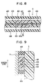
- the cord switch 4 of the present embodiment is comprised of an insulating holding member 403 of porous elastic material such as polyurethane or polyethylene which has a U-section intersecting at right angles the longitudinal direction, a first conducting member 401 thermally secured on the inner wall bottom of the insulating holding member 403, and a second conducting member 402 thermally secured to the opening of the insulating holding member 403.
- an insulating holding member 403 of porous elastic material such as polyurethane or polyethylene which has a U-section intersecting at right angles the longitudinal direction
- a first conducting member 401 thermally secured on the inner wall bottom of the insulating holding member 403, and a second conducting member 402 thermally secured to the opening of the insulating holding member 403.
- Thermal securing mentioned above is a welding process including disposing heated conducting members 401 and 402 on the insulating holding member 403, for thermally attaching the conducting members 401 and 402 to the insulating holding member 403.
- the space 405 provided between both the conducting members 401 and 402 is formed by melting the insulating holding member 403 by the heat used in thermally securing the first conducting member 401.
- the side visor 5 on which the external force F is acting upwardly with a foreign object pinched causes the conducting members 401 and 402 contact each other.
- the side visor 5 displaces toward the bent section 52a, thus deforming the insulating holding member 403 into contact with the conducting members 401 and 402.
- the insulating holding member 403 and the cover member 52 may be integrally formed.
- the stopper 52b may be formed on the side of the open end section of the cover member 52 as shown in Fig. 22.
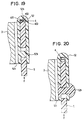
- an elastic member 52d such as rubber, spring, etc., which produces an elastic force for pressing normally the cord switch 4 so that the conducting members 401 and 402 contact each other when no external force is acting on the side visor 5. Therefore, as shown in Fig. 23A, when no external force is acting on the side visor 5, both the conducting members 401 and 402 is kept in contact. On the contrary, when the external force F is acting on the side visor 5, the cord switch 4 may be operated so that both the conducting members 401 and 402 in Fig. 23B will be separated thereby to detect pinching of a foreign object.
- an elastic member 52d such as rubber, spring, etc.
- an elastic member such as a plate spring may be used for bridging between the side visor 5 and the window frame 3, thereby enabling to prevent chattering of the side visor 5 caused by disturbance such as vehicle vibration.
- an elastic member such as a plate spring
- the present embodiment as shown in Fig. 24, has the cord switch 4 disposed in the lowermost edge portion 5a of the side visor 5. It should be noted that the cord switch is not limited to the cord switch 4 described in the fifth and sixth embodiments and may be any type of cord switch described in the first to fourth embodiments.
- a space 405 and both conducting members 401 and 403 are disposed in the edge portion 5a of the side visor 5 and a cover section 434 is provided for covering the edge side 5a which will come into contact with a foreign object.
- the cover section 434 is made of a porous elastic material such as polyurethane, polyethylene, etc.
- the cord switch 4 as shown in Figs. 26A and 26B, uses a flat conducting member as the first conducting member 42.
- the cord switch 4 of the present embodiment is disposed in the edge portion 5a of the window frame 3 or the side visor 5. It is desirable that the second and third conducting members 43 and 44 be disposed facing the side on which the external force F acts (in the direction in which the window glass 2 is opened).
- the first conducting member 42 will not deflect within the covered tube 41 but will move in between the second and third conducting members 43 and 44 if the covered tube 41 has a low rigidity when the external force F acts from a direction perpendicular to the linear direction connecting for example the centers 02, 03 of the second and third conducting members 43 and 44 to the first conducting member 42. Therefore, if the external force F acts, the first conducting member 42 and the second and third conducting members 43 and 44 will not contact each other, and therefore the external force F can not be sensed.
- the first conducting member 42 is formed flat, and therefore the first conducting member 42 will not move in between the second and third conducting members 43 and 44. Consequently the external force F can be sensed exactly.
- the cord switch 4 of the present embodiment is disposed in the edge portion 5a of the side visor 5.
- Both conducting members 401 and 402 are bent in V-shape cross section projecting in the direction in which the window glass 2 is opened, for the purpose of providing a wide sensing range.
- Both the conducting members 401 and 402 are held by an insulating holding member 403 made of a porous elastic member such as polyurethane, polyethylene, etc.
- the insulating holding member 403 serves also as a protective cover covering both the conducting members 401 and 402.
- the present embodiment has a purpose of reducing a malfunction of not only the cord switch 4 but the entire mechanism of the power window apparatus having the anti-pinching mechanism.
- cord switch (first cord switch) 4 for sensing the external force acting on the side visor 5 described in the above-described embodiments
- another cord switch (second cord switch) 40 is disposed in the weatherstrip 8 as shown in Fig. 28 and also a load detecting circuit is provided for detecting the driving load of the driving motor 1.
- the load detecting circuit comparing a detected value of a speed sensor 1a provided on the driving motor 1 as shown in Fig. 29, determines that the driving load exceeds a specific value and outputs an overload signal 1b to an AND gate 61 in the event the detected window moving speed output of the speed sensor 1a decreases below the specific value. Furthermore, both a first signal 4a generated when the first cord switch 4 senses an external force exceeding the specific value and a second signal 40a generated when the second cord switch 40 senses an external force exceeding a specific value are inputted to an OR gate 62. Together with a pinching detection signal 62a from the OR gate 62, a window closing signal 63a is inputted to an AND gate 61 from a motor driving circuit 63 for driving the driving motor 1. The window closing signal 63a is produced when the driving motor 1 is turning in a direction in which the window glass 2 is closed.
- the control circuit 65 operates the motor driving circuit 63 in accordance with the control signal 64a.
- the stop signal 61a is outputted from the AND gate 61, the control circuit 65 reverses or stop the driving motor 1.
- the power window apparatus of the present embodiment functions to reverse or stop the window glass by detecting the pinching of a foreign object in the event that an external force sensed by at least one of the first cord switch 4 and the second cord switch 40 exceeds a specific value and that the driving load of the driving motor 1 exceeds a specific value during window glass moving operation.
- the second cord switch 40 and the OR gate 62 are provided. However, it should be noticed that both of them may be eliminated, and the first signal 4a may be inputted from the first cord switch 4 directly to the AND gate 61. Also the second cord switch 40 may be disposed on the outside of the weatherstrip 8 to sense the external force acting on the window frame 3.
- the driving load is detected by detecting the rotational speed of the driving motor 1, but may be detected by detecting the value f the electric current flowing into the driving motor 1.
- the cord switch 4 is attached to the edge portion 5a of the side visor 5.
- the cord switch 4 has at least three conducting members (four in the present embodiment) 401, 402, 407 and 408 which are disposed in the elastically deformable insulating member 403 such as rubber to face one another with insulating space 405 thereamong.
- Each of the conducting members is partly embedded in the inner wall of the insulating member 403 under the condition that those are disposed spirally in the insulating member 403. Voltages are applied to the conducting members 401, 402, 407 and 408 so that one conducting member (member 401, for instance) is kept at a potential different from that of the remaining conducting members (members 402, 407 and 408, for instance).
- an external force F acting on the side visor 5 can be detected when the insulating member 403 deforms and the conducting members of different potentials contact.
- cord switch 4 In the cord switch 4 according to the present embodiment, other voltages may also be applied so that the conducting members 401, 402, 407 and 408 are kept at different potentials to detect the external force F.
- the edge portion 5a of the side visor 5 may be bent toward the vehicle interior and the cord switch 4 may be disposed at the bent portion 5b.
Landscapes
- Engineering & Computer Science (AREA)
- Mechanical Engineering (AREA)
- Window Of Vehicle (AREA)
- Power-Operated Mechanisms For Wings (AREA)
- Push-Button Switches (AREA)
- Insulated Conductors (AREA)
- Geophysics And Detection Of Objects (AREA)
Claims (16)
- Seitenblende für einen Fensterrahmen mit:einem in dem Fensterrahmen (3) gebildeten Seitenblendenkörperabschnitt (5) mit einer zur Abschirmung des äußeren Umfangs einer Fensteröffnung (3a) geformten Gestalt undeinem Meßfühler (4) zum Erfassen einer auf den Seitenblendenkörperabschnitt (5) ausgeübten äußeren Kraft.
- Seitenblende gemäß Anspruch 1, wobei:der Meßfühler (4) an einem Verbindungsteil (IV) des Seitenblendenkörperabschnitts (5) zwischen dem Fensterrahmen (3) und dem Seitenblendenkörperabschnitt (5) gelegen ist.
- Seitenblende gemäß Anspruch 1 oder 2, wobei:der Meßfühler (4) ein Paar Leitungselemente (401, 402) hat, die sich entlang einem dem Fensterrahmen (3) entsprechenden Teil erstrecken und einander gegenüberliegend durch einen vorbestimmten Raum (405) angeordnet sind; undein Isolierungshalterungselement (403) aus einem porösen elastischem Material zum Halten des Paars Leitungselemente (401, 402), um den Raum dazwischen zu bilden.
- Seitenblende gemäß Anspruch 3, wobei:das Isolierungshalterungselement (403) zumindest aus Polyurethan und/oder Polyethylen hergestellt ist.
- Seitenblende gemäß Anspruch 3, wobei:der Meßfühler (4) an einem Kantenabschnitt (5a) des Seitenblendenkörperabschnitts gelegen ist, welcher einem Verbindungsteil des Seitenblendenkörperabschnitts (5) zwischen dem Fensterrahmen und dem Seitenblendenkörperabschnitt gegenüberliegt.
- Seitenblende gemäß Anspruch 5, wobei der Meßfühler folgendes aufweist:eine Vielzahl von Leitungselementen (401, 402, 407, 408), die sich spiralförmig entlang einem dem Fensterrahmen entsprechenden Teil erstrecken und einander gegenüberliegend durch einen vorherbestimmten Raum dazwischen angeordnet sind; undein Isolierungshalterungselement (403), das an dem Kantenabschnitt (5a) angebracht ist und die Leitungselemente (401, 402, 407, 408) darin hält.
- Fensterheberantriebsvorrichtung, die eine Seitenblende gemäß Anspruch 1 aufweist, wobei die Fensterhebervorrichtung außerdem folgendes aufweist:einen Fensterkörper (2) zum Öffnen und Schließen der durch den Fensterrahmen (3) gebildeten Fensteröffnung (3a); undein Fensterschließvorgangsstoppelement (1, 6; 61 - 65) zum Stoppen einer Schließbewegung des Fensterkörpers (2), wenn die von dem Meßfühler (4) gemessene externe Kraft einen voreingestellten Wert überschreitet.
- Fensterhebervorrichtung gemäß Anspruch 7, wobei:der Meßfühler (4) an einem Verbindungsteil (IV) gelegen ist, wo die Seitenblende (5) an den Fensterrahmen (3) angebracht ist.
- Fensterhebervorrichtung gemäß Anspruch 8, die außerdem folgendes aufweist:ein mit dem Fensterrahmen (3) verbundenes Bedeckungselements (52) zum Halten der in der Richtung nach oben und unten verschiebbaren Seitenblende (5) und zum Bedecken des Verbindungsteils von oben, wobei der Meßfühler (4) innerhalb des Bedeckungselements (52) gelegen ist.
- Fensterhebervorrichtung gemäß Anspruch 8 oder 9, wobei der Meßfühler (4) folgendes aufweist:ein Paar Leitungselemente (401, 402), die sich entlang dem Fensterrahmen (3) erstrecken und einander gegenüberliegend mit einem vorherbestimmten Abstand dazwischen angeordnet sind;ein Halterungselement (403) zum Halten des Paars von Halterungselementen (401, 402); undein Verschiebungselement (404), das in Bezug auf das Halterungselement (403) und das Paar von Leitungselementen (401, 402) verschiebbar angebracht ist,wobei das Halterungselement (403) an das eine von dem Fensterrahmen (3) und der Seitenblende (5) verbunden ist, und das Verschiebungselement (404) an das andere von dem Fensterrahmen (3) und der Seitenblende (5) verbunden ist.
- Fensterhebervorrichtung gemäß Anspruch 10, wobei:das Paar Leitungselemente (401, 402) einander gegenüberliegend in einer Richtung angeordnet ist, in welcher der Fensterkörper (2) geöffnet und geschlossen wird; unddas Verschiebungselement (404) mit einem Verschiebungsbegrenzungselement (3, 405) zum Begrenzen der Verschiebung des Verschiebungselements (404) in einer Richtung ausgestattet ist, die die Richtung schneidet, in welcher der Fensterkörper (2) geöffnet und geschlossen wird.
- Fensterhebervorrichtung gemäß einem der Ansprüche 7 bis 9,
wobei:der Meßfühler (4) ein Paar Leitungselemente (401, 402) aufweist, die sich entlang dem Fensterrahmen (3) erstrecken und einander gegenüberliegend durch einen vorbestimmten Raum angeordnet sind; undein Isolierungshalterungselement (403) aus einem porösen elastischen Material zum Halten des Paars von Leitungselementen (401, 402), um hierdurch den Raum (405) zu definieren. - Fensterhebervorrichtung gemäß Anspruch 12, wobei:das Isolierungshalterungselement (403) aus wenigstens einem aus Polyurethan und/oder Polyethylen hergestellt ist.
- Fensterhebervorrichtung, die eine Seitenblende gemäß Anspruch 1 aufweist, wobei die Fensterhebervorrichtung außerdem folgendes aufweist:einen Fensterkörper (2) zum Öffnen und Schließen einer in einem Fensterrahmen (3) gebildeten Fensteröffnung (3a), wobei die Seitenblende entlang einer äußeren Umgrenzung des Fensterrahmens (3) zur Abschirmung einer äußeren Begrenzung der Fensteröffnung (3a) vorgesehen ist;ein Fensterkörperantriebselement (1) zum Antrieb des Fensterkörpers (2);ein Lasterfassungselement zum Erfassen einer Antriebslast des Fensterkörperantriebselements (1); undFensterschließvorgangsstoppelement (61-65) zum Stoppen der Bewegung des Fensterkörpers (2) beim Verschließen, wenn die durch den Meßfühler (4) gemessene äußere Kraft einen voreingestellten Wert überschreitet und auch wenn ein durch das Lasterfassungselement (1a) erfasster Erfassungswert einen voreingestellten Wert überschreitet.
- Fensterhebervorrichtung, die eine Seitenblende gemäß Anspruch 1 aufweist, wobei die Fensterhebervorrichtung außerdem folgendes aufweist:einen Fensterkörper (2) zum Öffnen und Schließen einer in einem Fensterrahmen (3) gebildeten Fensteröffnung (3a), wobei die Seitenblende entlang einer äußeren Umgrenzung des Fensterrahmens (3) zur Abschirmung eines äußeren Umfangs der Fensteröffnung (3a) vorgesehen ist;einen ersten Meßfühler (4) zum Messen einer externen Kraft, die auf die Seitenblende (5) ausgeübt wird;einen an dem Fensterrahmen (3) angeordneten zweiten Meßfühler (4) zum Messen einer auf den Fensterrahmen (3) ausgeübten externen Kraft;ein Fensterkörperantriebselement (1) zum Antrieb des Fensterkörpers (2);ein Lasterfassungselement zum Erfassen einer Antriebslast des Fensterkörperantriebselements (1); undFensterschließvorgangsstoppelement (61-65) zum Stoppen der Bewegung des Fensterkörpers (2) beim Schließen, wenn die durch den Meßfühler (4) gemessene äußere Kraft einen voreingestellten Wert überschreitet und auch wenn ein durch das Lasterfassungselement (1a) erfasster Erfassungswert einen voreingestellten Wert überschreitet.
- Fensterheberantriebsvorrichtung gemäß Anspruch 15, wobei:der zweite Meßfühler (40) an einem Dichtstreifen (8) angeordnet ist, die entlang einer äußeren Umgrenzung des Fensterrahmens (3) eingebaut ist.
Applications Claiming Priority (9)
| Application Number | Priority Date | Filing Date | Title |
|---|---|---|---|
| JP10163996 | 1996-04-23 | ||
| JP10163996 | 1996-04-23 | ||
| JP101639/96 | 1996-04-23 | ||
| JP581797 | 1997-01-16 | ||
| JP581797 | 1997-01-16 | ||
| JP5817/97 | 1997-01-16 | ||
| JP02071597A JP3834909B2 (ja) | 1996-04-23 | 1997-02-03 | 車両用動力付窓開閉装置 |
| JP2071597 | 1997-02-03 | ||
| JP20715/97 | 1997-02-03 |
Publications (3)
| Publication Number | Publication Date |
|---|---|
| EP0803628A2 EP0803628A2 (de) | 1997-10-29 |
| EP0803628A3 EP0803628A3 (de) | 1998-05-27 |
| EP0803628B1 true EP0803628B1 (de) | 2001-12-19 |
Family
ID=27276912
Family Applications (1)
| Application Number | Title | Priority Date | Filing Date |
|---|---|---|---|
| EP97106638A Expired - Lifetime EP0803628B1 (de) | 1996-04-23 | 1997-04-22 | Seitenblende mit Einklemmschutzsensor und Fensterheberantriebsvorrichtung unter Verwendung derselben |
Country Status (5)
| Country | Link |
|---|---|
| US (1) | US5880421A (de) |
| EP (1) | EP0803628B1 (de) |
| JP (1) | JP3834909B2 (de) |
| CA (1) | CA2203431C (de) |
| DE (1) | DE69709225T2 (de) |
Families Citing this family (31)
| Publication number | Priority date | Publication date | Assignee | Title |
|---|---|---|---|---|
| WO1997021235A1 (en) | 1995-12-04 | 1997-06-12 | Hitachi Cable, Ltd. | Cord switch and pressure sensor |
| JPH10321070A (ja) * | 1996-07-09 | 1998-12-04 | Ebatsuku:Kk | 管状スイッチ及びその接続器具 |
| WO1999034081A1 (en) * | 1997-12-24 | 1999-07-08 | Asmo Co., Ltd. | Automatic opening and closing device |
| JP2000088677A (ja) * | 1998-09-09 | 2000-03-31 | Kinugawa Rubber Ind Co Ltd | 感圧センサ |
| EP1011184A1 (de) * | 1998-12-15 | 2000-06-21 | Talltec Technologies Holdings S.A. | Sicherheitsvorrichtung für einen elektromotorischen Fensterheber und Verfahren zur Ausführung dieser Vorrichtung |
| US6389752B1 (en) * | 1999-06-21 | 2002-05-21 | Schlegel Corporation | Touch sensitive trapping protector for power operated closing devices |
| US6362584B1 (en) * | 2000-04-19 | 2002-03-26 | Meritor Light Vehicle Technology L.L.C. | Virtual sensor for window position |
| US6337549B1 (en) | 2000-05-12 | 2002-01-08 | Anthony Gerald Bledin | Capacitive anti finger trap proximity sensor |
| US7132642B2 (en) * | 2001-07-09 | 2006-11-07 | Nartron Corporation | Anti-entrapment systems for preventing objects from being entrapped by translating devices |
| US6782759B2 (en) * | 2001-07-09 | 2004-08-31 | Nartron Corporation | Anti-entrapment system |
| US7162928B2 (en) * | 2004-12-06 | 2007-01-16 | Nartron Corporation | Anti-entrapment system |
| US7293467B2 (en) * | 2001-07-09 | 2007-11-13 | Nartron Corporation | Anti-entrapment system |
| US7507708B2 (en) * | 2003-02-26 | 2009-03-24 | Pharma Mar, S.A.U. | Antitumoral compounds |
| US7226112B2 (en) * | 2003-10-02 | 2007-06-05 | Nicholas Plastics Incorporated | Pinch warning and illumination system |
| US7312591B2 (en) * | 2005-03-11 | 2007-12-25 | Npc Corporation | Powered panel moving system |
| DE202005011044U1 (de) * | 2005-07-06 | 2006-11-16 | Brose Fahrzeugteile Gmbh & Co. Kommanditgesellschaft, Coburg | Sensorsystem für eine Einklemmschutzvorrichtung |
| US20070095595A1 (en) * | 2005-11-02 | 2007-05-03 | Arvinmeritor Light Vehicle Systems-France | Anti-squeeze method utilizing airbag information |
| US7342373B2 (en) * | 2006-01-04 | 2008-03-11 | Nartron Corporation | Vehicle panel control system |
| JP2007205092A (ja) | 2006-02-03 | 2007-08-16 | Tachibana Eletech Co Ltd | 信号入力方法および開閉制御装置 |
| JP4680848B2 (ja) * | 2006-07-31 | 2011-05-11 | アスモ株式会社 | 挟み込み検出装置及び感圧センサの製造方法 |
| US7938376B2 (en) | 2008-08-22 | 2011-05-10 | Control Solutions LLC | Mounting clips and sensor installations for motorized vehicle doors |
| US7959211B2 (en) * | 2008-08-25 | 2011-06-14 | Control Solutions LLC | Sensor installations for motorized vehicle doors |
| US8493081B2 (en) * | 2009-12-08 | 2013-07-23 | Magna Closures Inc. | Wide activation angle pinch sensor section and sensor hook-on attachment principle |
| US9234979B2 (en) | 2009-12-08 | 2016-01-12 | Magna Closures Inc. | Wide activation angle pinch sensor section |
| JP5813894B1 (ja) * | 2015-03-16 | 2015-11-17 | 株式会社城南製作所 | 車両用窓ガラス昇降装置、車両用ドア、および車両 |
| US12297683B2 (en) | 2019-09-10 | 2025-05-13 | Toyota Motor Engineering & Manufacturing North America, Inc. | Extended coverage for a sensor along a complex contour |
| CN110821338B (zh) * | 2019-11-14 | 2021-03-30 | 南通迈程汽车技术有限公司 | 一种升降平稳的机械式防夹车窗 |
| US12000192B2 (en) * | 2019-11-15 | 2024-06-04 | Uusi, Llc | Sensor for anti-entrapment system |
| CN110939343A (zh) * | 2019-12-13 | 2020-03-31 | 深圳南方德尔汽车电子有限公司 | 一种电动车窗的防夹控制装置 |
| CN114295403B (zh) * | 2021-12-31 | 2024-04-09 | 北京市地铁运营有限公司地铁运营技术研发中心 | 一种站台门远程故障检测方法、系统、装置及存储介质 |
| US11993970B2 (en) * | 2022-02-21 | 2024-05-28 | Ford Global Technologies, Llc | Window system that has a pressure-sensitive material and an associated object detection method |
Family Cites Families (17)
| Publication number | Priority date | Publication date | Assignee | Title |
|---|---|---|---|---|
| GB1198439A (en) * | 1966-12-05 | 1970-07-15 | Lucas Industries Ltd | Safety Arrangements for Motor Operated Windows in Road Vehicles |
| US3830018A (en) * | 1970-02-17 | 1974-08-20 | Toyota Motor Co Ltd | Safety device for power window |
| US3710050A (en) * | 1970-09-14 | 1973-01-09 | A Richards | Electronic pressure sensitive switch |
| US3793772A (en) * | 1970-11-24 | 1974-02-26 | Golde Gmbh H T | Safety molding for electrically actuated sliding windows |
| US3693150A (en) * | 1971-06-03 | 1972-09-19 | Edward N Daniels | Vehicle window actuated alarm device |
| DE3818456A1 (de) * | 1988-05-31 | 1989-12-14 | Kabelmetal Electro Gmbh | Sicherheitsvorrichtung fuer eine automatisch bewegte fensterscheibe eines kraftfahrzeugs |
| FR2642546B1 (fr) * | 1989-01-31 | 1991-05-17 | Jaeger | Perfectionnements au detecteur d'obstacle |
| FR2643171A1 (fr) * | 1989-02-13 | 1990-08-17 | Jaeger | Systeme detecteur d'obstacle comprenant un ensemble de connexion perfectionne |
| JPH06260054A (ja) * | 1991-05-30 | 1994-09-16 | Nissei Denki Kk | 感圧スイッチ |
| DE9111806U1 (de) * | 1991-09-20 | 1993-01-28 | Farmont, Rolf, Dr., 40474 Düsseldorf | Sicherheitsschalter für ein elektrisch betriebenes Schiebedach |
| US5296658A (en) * | 1992-09-25 | 1994-03-22 | Rockwell International Corporation | Safety edge switch for detection of obstructions encountered by a moving object |
| JP2962340B2 (ja) * | 1993-06-14 | 1999-10-12 | 三菱自動車工業株式会社 | パワーウインドウ装置 |
| DE9321338U1 (de) * | 1993-08-09 | 1997-06-12 | Metzeler Automotive Profiles Gmbh, 88131 Lindau | Einklemmschutz für kraftbetätigte Schließeinrichtungen |
| GB9418402D0 (en) * | 1994-09-13 | 1994-11-02 | Rover Group | A security system and detector means therefor |
| US5592060A (en) * | 1995-07-10 | 1997-01-07 | Webasto Sunroofs Inc. | System for sensing an obstruction between a movable panel and a stationary panel frame |
| US5754017A (en) * | 1995-12-26 | 1998-05-19 | Asmo Co., Ltd. | Power window with detecting function of sticking of foreign matter |
| JPH09288931A (ja) * | 1996-04-22 | 1997-11-04 | Asmo Co Ltd | コードスイッチ |
-
1997
- 1997-02-03 JP JP02071597A patent/JP3834909B2/ja not_active Expired - Fee Related
- 1997-03-27 US US08/826,129 patent/US5880421A/en not_active Expired - Fee Related
- 1997-04-22 CA CA002203431A patent/CA2203431C/en not_active Expired - Fee Related
- 1997-04-22 DE DE69709225T patent/DE69709225T2/de not_active Expired - Lifetime
- 1997-04-22 EP EP97106638A patent/EP0803628B1/de not_active Expired - Lifetime
Also Published As
| Publication number | Publication date |
|---|---|
| JPH10258634A (ja) | 1998-09-29 |
| EP0803628A2 (de) | 1997-10-29 |
| DE69709225T2 (de) | 2002-08-08 |
| US5880421A (en) | 1999-03-09 |
| DE69709225D1 (de) | 2002-01-31 |
| JP3834909B2 (ja) | 2006-10-18 |
| CA2203431A1 (en) | 1997-10-23 |
| EP0803628A3 (de) | 1998-05-27 |
| CA2203431C (en) | 2001-01-16 |
Similar Documents
| Publication | Publication Date | Title |
|---|---|---|
| EP0803628B1 (de) | Seitenblende mit Einklemmschutzsensor und Fensterheberantriebsvorrichtung unter Verwendung derselben | |
| EP0666956B1 (de) | Sicherheitskontaktschiene zur feststellung von auf einen bewegenden gegenstand auftreffenden hindernissen | |
| US7958672B2 (en) | Opening/closing device | |
| US20070182351A1 (en) | Power lift gate for automotive vehicle | |
| US20080303685A1 (en) | Installation structure of capacitance sensor and assembly method of the same | |
| CA1148589A (en) | Sensitive door edges | |
| US6163080A (en) | Anti-pinching system based on modification of the light conductivity of an optical fibre for automatic car windows | |
| US5920044A (en) | Pressure-responsive switch | |
| JP2021183800A (ja) | 挟み込み防止システムが組み込まれた車体部品 | |
| KR101373292B1 (ko) | 차량의 장애물 감지용 센서스트립 조립체 | |
| CN107004530A (zh) | 触控传感器单元 | |
| JP7518565B2 (ja) | 静電容量変化を用いた人体挟み込み防止装置 | |
| WO2004065925A1 (ja) | 感圧センサ、物体検出装置、及び開閉装置、並びに感圧センサの製造方法 | |
| US6223467B1 (en) | Motor vehicle sensor arrangement for detecting jamming | |
| US6779303B2 (en) | Vehicular power window safety device | |
| US7098445B2 (en) | Load detecting device | |
| JP2007056522A (ja) | スライドドアの挟み込み検出構造 | |
| JP3853958B2 (ja) | 挟み込み検出装置 | |
| US5801347A (en) | Cord switch having alternate insulating members | |
| US20010013203A1 (en) | Device for recognition of obstruction of closure | |
| EP1031696A2 (de) | Fensterbetätigungsüberwachungssystem mit einem Drucksensor und einem Lastsensor | |
| JP5913494B2 (ja) | 接触センサ | |
| JPH09158611A (ja) | 自動車用開閉部材の開閉状態検出装置 | |
| JP5694800B2 (ja) | 異物検出装置 | |
| KR19990072871A (ko) | 광섬유의빛전도율변경을기초로한자동차윈도우를위한개선된끼임방지장치 |
Legal Events
| Date | Code | Title | Description |
|---|---|---|---|
| PUAI | Public reference made under article 153(3) epc to a published international application that has entered the european phase |
Free format text: ORIGINAL CODE: 0009012 |
|
| AK | Designated contracting states |
Kind code of ref document: A2 Designated state(s): DE FR GB |
|
| PUAL | Search report despatched |
Free format text: ORIGINAL CODE: 0009013 |
|
| AK | Designated contracting states |
Kind code of ref document: A3 Designated state(s): DE FR GB |
|
| 17P | Request for examination filed |
Effective date: 19980908 |
|
| 17Q | First examination report despatched |
Effective date: 20000323 |
|
| GRAG | Despatch of communication of intention to grant |
Free format text: ORIGINAL CODE: EPIDOS AGRA |
|
| GRAG | Despatch of communication of intention to grant |
Free format text: ORIGINAL CODE: EPIDOS AGRA |
|
| GRAH | Despatch of communication of intention to grant a patent |
Free format text: ORIGINAL CODE: EPIDOS IGRA |
|
| GRAH | Despatch of communication of intention to grant a patent |
Free format text: ORIGINAL CODE: EPIDOS IGRA |
|
| GRAA | (expected) grant |
Free format text: ORIGINAL CODE: 0009210 |
|
| AK | Designated contracting states |
Kind code of ref document: B1 Designated state(s): DE FR GB |
|
| REG | Reference to a national code |
Ref country code: GB Ref legal event code: IF02 |
|
| REF | Corresponds to: |
Ref document number: 69709225 Country of ref document: DE Date of ref document: 20020131 |
|
| ET | Fr: translation filed | ||
| PLBE | No opposition filed within time limit |
Free format text: ORIGINAL CODE: 0009261 |
|
| STAA | Information on the status of an ep patent application or granted ep patent |
Free format text: STATUS: NO OPPOSITION FILED WITHIN TIME LIMIT |
|
| 26N | No opposition filed | ||
| PGFP | Annual fee paid to national office [announced via postgrant information from national office to epo] |
Ref country code: GB Payment date: 20100325 Year of fee payment: 14 |
|
| PGFP | Annual fee paid to national office [announced via postgrant information from national office to epo] |
Ref country code: FR Payment date: 20100521 Year of fee payment: 14 |
|
| PGFP | Annual fee paid to national office [announced via postgrant information from national office to epo] |
Ref country code: DE Payment date: 20100430 Year of fee payment: 14 |
|
| REG | Reference to a national code |
Ref country code: DE Ref legal event code: R119 Ref document number: 69709225 Country of ref document: DE |
|
| REG | Reference to a national code |
Ref country code: DE Ref legal event code: R119 Ref document number: 69709225 Country of ref document: DE |
|
| GBPC | Gb: european patent ceased through non-payment of renewal fee |
Effective date: 20110422 |
|
| REG | Reference to a national code |
Ref country code: FR Ref legal event code: ST Effective date: 20111230 |
|
| PG25 | Lapsed in a contracting state [announced via postgrant information from national office to epo] |
Ref country code: FR Free format text: LAPSE BECAUSE OF NON-PAYMENT OF DUE FEES Effective date: 20110502 |
|
| PG25 | Lapsed in a contracting state [announced via postgrant information from national office to epo] |
Ref country code: GB Free format text: LAPSE BECAUSE OF NON-PAYMENT OF DUE FEES Effective date: 20110422 |
|
| PG25 | Lapsed in a contracting state [announced via postgrant information from national office to epo] |
Ref country code: DE Free format text: LAPSE BECAUSE OF NON-PAYMENT OF DUE FEES Effective date: 20111031 |