EP0803032B1 - Chaine de gestion de l'energie - Google Patents
Chaine de gestion de l'energie Download PDFInfo
- Publication number
- EP0803032B1 EP0803032B1 EP96945845A EP96945845A EP0803032B1 EP 0803032 B1 EP0803032 B1 EP 0803032B1 EP 96945845 A EP96945845 A EP 96945845A EP 96945845 A EP96945845 A EP 96945845A EP 0803032 B1 EP0803032 B1 EP 0803032B1
- Authority
- EP
- European Patent Office
- Prior art keywords
- guide groove
- energy transmission
- chain
- adjacent
- transmission chain
- Prior art date
- Legal status (The legal status is an assumption and is not a legal conclusion. Google has not performed a legal analysis and makes no representation as to the accuracy of the status listed.)
- Expired - Lifetime
Links
Images


Classifications
-
- F—MECHANICAL ENGINEERING; LIGHTING; HEATING; WEAPONS; BLASTING
- F16—ENGINEERING ELEMENTS AND UNITS; GENERAL MEASURES FOR PRODUCING AND MAINTAINING EFFECTIVE FUNCTIONING OF MACHINES OR INSTALLATIONS; THERMAL INSULATION IN GENERAL
- F16G—BELTS, CABLES, OR ROPES, PREDOMINANTLY USED FOR DRIVING PURPOSES; CHAINS; FITTINGS PREDOMINANTLY USED THEREFOR
- F16G13/00—Chains
- F16G13/12—Hauling- or hoisting-chains so called ornamental chains
- F16G13/16—Hauling- or hoisting-chains so called ornamental chains with arrangements for holding electric cables, hoses, or the like
-
- H—ELECTRICITY
- H02—GENERATION; CONVERSION OR DISTRIBUTION OF ELECTRIC POWER
- H02G—INSTALLATION OF ELECTRIC CABLES OR LINES, OR OF COMBINED OPTICAL AND ELECTRIC CABLES OR LINES
- H02G11/00—Arrangements of electric cables or lines between relatively-movable parts
- H02G11/006—Arrangements of electric cables or lines between relatively-movable parts using extensible carrier for the cable, e.g. self-coiling spring
Definitions
- the invention relates to a first type of energy chains for guiding hoses, cables or the like between two connection points, the chain links each have two side parts that have at least one crossbar are connected to each other, with those assembled from side parts Bands of the energy chain from alternating mutually arranged inner plates and outer plates exist, the inner link plates the inside of the energy chain facing overlapping areas and the outer flaps have outwardly projecting overlapping areas and pivotable about them in one plane are connected.
- the invention relates to a second type of energy chain for guiding hoses, cables or the like between two connection points, the chain links each two cranked side parts with one cranked to the outside Area and an inwardly cranked area, wherein the side parts with each other via at least one crossbar are connected and the side parts of adjacent chain links have overlapping areas and over these are articulated together.
- Energy chains of the first type with alternating ones Inner and outer plates are for example from DE 43 25 259 C2 known, while using energy chains of the second type cranked side parts, for example in DE 34 31 531 A1 are described.
- energy supply chains serve the supply of flexible ones Supply lines from a fixed starting point to a mobile consumer.
- the energy chains following the movement of the consumer in one move vertically arranged level.
- Applications of the energy supply chain with an arc sagging areas i.e. when the upper run of the energy chain is located freely above the lower run and after sags at the bottom, occur under tensile and compressive loads of the unsupported part of the energy chain high moments acting on the joint area of the chain links on.
- Has the energy supply chain used in this way insufficient lateral stability this can lead to a Swiveling the overlapping areas from the swivel plane lead so that the hinge pin no longer evenly used by the adjacent side panels become. Rather, zones occur higher at the hinge pins mechanical stresses that ultimately lead to breakage the hinge pin can guide. Similar signs of wear are also in the ascending area of the bends observed by energy chains when the upper run is sliding is performed on the lower run.
- the object of the present invention is therefore, energy chains of the two types mentioned at the beginning, which have high lateral stability and, especially in Lateral position mounted, do not sag and the simple and are inexpensive to manufacture.
- this task is performed in energy chains of the first type in that at least one of the in a band of the energy chain adjacent side parts at least one is parallel to the pivoting plane extending guide groove and the adjacent to this Side part over the entire swivel angle with at least one extending parallel to the pivoting plane Guide part engages in one of the guide grooves.
- the guide part can be parallel to the pivoting plane extending projection be formed, the face towards the adjacent chain link on the side part is arranged.
- the task solved according to the invention in that the free end of an overlapping Area of the side part at least on the front a projection extending parallel to the pivoting plane, and, opposite this, at least one yourself has a guide groove extending parallel to the pivoting plane, the side part with at least one projection in engages at least one guide groove in the adjacent side part.
- the guide groove provided according to the invention can be a comparatively short length, as long as guaranteed is that always a guide part of the adjacent side part engages in the guide groove.
- the guide groove or the flanks of the same are also broken, so that the Guide groove ultimately only by a single or by a number of spaced apart projections is defined. Is the part that engages in the guide groove of the adjacent side part opposite both sides of the Guide groove with little play, so is a tilt the side parts in both directions from the swivel plane prevented and the energy chain in both of them Side layers can be used.
- the outer edge can in particular also serve as the guide part serve the overlapping area of the side part.
- the present invention is particularly independent applicable from the other design of the crossbars.
- the Crosspieces can be molded in one piece on the side parts or by means of known latching or hinge connections with these be connected.
- the crossbars can also over a extend larger longitudinal region of the side parts, so that in essentially closed chain links result.
- the crossbars can also be divided lengthways be carried out so that in the embodiment according to the invention the chain links the stability of the same is increased.
- the Projection a smaller thickness than the side part in it the protrusion adjacent area and is from the outer surface of the side part spaced. This allows the side panels be manufactured in a small width. It did it has been shown that such a dimensioning of the projection is completely sufficient to provide adequate lateral stability of the energy supply chain.
- Such embodiment can also the outside of the guide groove limiting area of the side part to such lateral extent that he is not limited about the height of the adjacent area of the adjacent side part protrudes. This makes a compact design in of the energy chain, created at the same time laterally protruding areas that cause the chain links to get caught of the energy supply chain could be avoided.
- the guide groove and the projection are advantageous mutually adjacent side parts are designed as circular arc segments, covering essentially the entire height of the extend overlapping area of the side parts.
- a maximum contact surface of the engaging in the guide groove Guide part with the flank of the guide groove in Given a bend or the like., Which creates an energy chain with particularly high lateral stability, which in particular to accommodate heavy hoses, cables or the like is suitable.
- the guide groove and the projection engaging in it are adjacent Side panels can be limited with stop faces the pivoting angle of the two side parts his.
- the stop surfaces can be in the guide groove arranged or of the projections parallel to the pivoting plane protruding projections may be provided in engage corresponding recesses.
- the stops maximum distance from the joint areas, whereby there are particularly favorable leverage ratios and the side parts not through those perpendicular to their main plane Blind holes are weakened.
- the side parts by integrally molded hinge pins and corresponding Recesses connected to each other, the height of the hinge pin and the depth with which the guide part fits into the associated guide groove extends, are dimensioned so that the Hinge pin in cooperation with the guide groove and Form a snap connection.
- the chain links can thus snap together at an incline be attached.
- the height of the hinge pin and the depth of the engaging in the guide groove protrusion so that the side parts while exercising a pressure or a light blow to each other can be locked in place.
- the side parts are still easy to attach or detach from each other, due to the close locking connection at the same time high lateral stability of the energy chain results.
- such side parts can be produced in one piece, whereby the assembly effort and the manufacturing costs are minimized.
- the hinge pin and / or the Projection and / or the corresponding guide groove beveled Have outer edges.
- a particularly advantageous embodiment is when the bevelled edges of the projection and / or the corresponding one Guide groove are provided with indentations.
- partial areas can be one side part by the on the adjacent side part arranged indentations are performed so that the Attachment of the side panels to each other is further facilitated.
- the overlapping Areas of the inner plates and outer plates with each other can be connected by detachable hinge pins and the inner straps to the outside of the chain and the outer plates to the inside of the chain have the above central regions, it should be provided that the Guide part at the free ends of the overlapping Areas of the outer plate and the inner plate and the guide groove each facing the adjacent side panels Sides of the middle areas of the outer plate and the inner plate are arranged.
- a particularly advantageous training consists of the guide part at the free ends the overlapping areas of the outer plate and the inner plate and the guide groove on each of the adjacent side parts facing sides of the central area of the inner tabs and to arrange the outer plates.
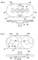
- the side parts 1 are cranked, whereby the pre-cranked ones that overlap with adjacent chain links Areas 2A on their inside each with one piece molded hinge pin 3 and with a pivot angle adjacent side parts limiting stop 4 are provided.
- the recessed area 2B the side part has a recess 5 into which a hinge pin 3 of the adjacent side part is insertable, and one Recess 6 on that with a stop 4 of the adjacent Partially corresponds.
- the side part 1 is according to the invention provided with a guide groove 7 on the overlapping Area 2A, opposite the free end thereof, is arranged and the bottom of which is parallel in one plane the pivoting plane of the side part 1 extends.
- the projection 8 which in the assembled state of the energy chain in the guide groove 7 of the adjacent side part engages so that tilting or an offset of neighboring Side parts against each other in a direction perpendicular to Swivel level is limited and an energy chain high lateral stability results.
- the guide groove 7 and the engaging in the guide groove 7 of the adjacent side part Projection 8 are designed as circular arc segments that extend over the entire height of the side part 1, so that the projection 8 over the entire pivoting range in the largest possible area in the guide groove 7 is led. This means that the energy chain is also for designed for high lateral loads.
- the projection 8 extends only over half the thickness of the overlapping Area 2A and closes flush on the inside this, so that the projection 8 encompassing the outer Flank 9 of the guide groove 7 to the outside not over the adjacent Area of the adjacent side part protrudes. This is both a particularly compact embodiment before, at the same time snagging the chain links with others Components is avoided.
- the hinge pin is also 3 provided with a ramp 11, which in Longitudinal direction of the side part 1 is arranged.
- Adjacent side parts become the protruding one under oblique guidance Area 2A of the first side part with the recessed Area 2B of the second side part for overlap brought so that the projection arranged on the first side part 8 engages in the guide groove 7 of the second side part and the ramp slope 11 of the threaded bolt 3 of the first side part essentially flat on the recessed Area 2B of the second side part abuts.
- the assembly is still by the on the projection 8 and indentations 12 arranged on the slope 10 of the flank 9 and 13 additionally facilitated, which are arranged such that when the side parts are fastened, the indentations correspond Projections 8 and guide grooves 7 on the same Are arranged in height and are guided past each other.
- the Indentations are designed in the manner of bevels, which is less inclined than the outer edges of the protrusion 8 and the flank 9 of the guide groove.
- the dents can also extend the entire length of the ledge 8 or the flank 9 of the guide groove or curved be executed.
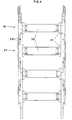
- Fig. 3 shows an energy chain in plan view, the consists of bands of identical side parts, the Side parts of opposite bands are each mirror images are executed to each other. Opposite side panels are by means of molded-on locking bars across the cross bars 15 with one another connected. It is made clear once again that tilting or an offset of adjacent side parts from the swivel plane in a direction perpendicular to this (arrow), by the engaging in the guide grooves 7 projections 8 of each adjacent side part is prevented.
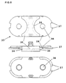
- FIGS. 4 to 6 show a further embodiment, where the side straps assembled from side parts the energy chain from two different types of Side panels, outer and inner tabs that alternate are arranged to each other.
- the outer plates 16 have two overlapping areas 17A, 17B projecting outwards are arranged and each with a one-piece molded hinge pin 18 and stop 19 are provided. Of others are on the end face at the overlapping regions 17A, 17B, projections 20 projecting into the pivoting plane, which extend over the entire height of the outer plates 16.
- the inner straps 21, which are adjacent to the outer straps 16, have overlapping areas 22A, 22B on the inside of the energy chain facing and provided with recesses 23, 24 are with the hinge pin 18 and the stops 19th of the adjacent outer plates correspond.
- the inner tabs 21 have at their central regions 25, the free Facing ends of overlapping portions 22A, 22B, guide grooves 26 into which the projections 20 of the outer plates 16, corresponding to the assembly of the side parts 1 according to FIGS. 1-3, can be introduced.
- the outer flank 27 of the guide groove 26 and the projections 20 are like those of the side parts 1 executed and in particular with easy assembly Indentations 28 provided.
- the side parts in turn Recesses 29 on the overlapping areas of the adjoin each adjacent side part and dismantle lighten adjacent side parts.
- the outer and inner plates are connected to one another via crosspieces 30 connected to the inside of the energy chain pointing locking bars are attachable.
- the crossbars show 30 at their ends widenings 31, so that at the Outer plates 16 fastened crossbars 30 with the neighboring ones Overlap inner tabs 21.
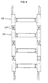
- each is the articulated overlapping with the adjacent side panels Area of a side part with one as a guide part acting projection 37 and each long side of the central regions 34, 35 with one with the projection of the adjacent side part corresponding guide groove 38 provided.
- each side part on the outside and inside of an adjacent one Side part guided, creating an energy chain with particularly high lateral stability results.
- the guide groove 38 and the projection 37 each adjacent to that in the Arranged center plane of the side part, the lateral extent of the guide groove 38 and the half-thickness protrusion 37 of the central portion 34, 35 correspond.
- the side parts are under parallel Displacement attached to each other in the swivel plane, so that the corresponding ones with each other Projections and guide grooves of adjacent side parts into one another intervention. If the side parts are in their target position, so these are introduced by inserting hinge pins the through holes 36 attached to each other.
- the side parts 32, 33 are also provided with stops 39 provided, which are arranged in the guide grooves 38 and have lateral stop surfaces. This will make the guide groove 38 divided into two sections, each in a projection 37 of the adjacent side part engages.
- the Projections 37 of the side part are through an incision separated from each other. The incision extends over a larger circumferential area than the stop 39, which defines the pivoting range of the side parts becomes.
- the guide groove can also have an indentation be provided, in which a projection of the neighboring Side part engages with undersize.
- FIG. 9 shows a top view of the energy chain, in which the comb-like engagement of adjacent side parts is made clear. Also in this embodiment recesses 29 are provided for the disassembly of the energy chain facilitate.
Landscapes
- Engineering & Computer Science (AREA)
- General Engineering & Computer Science (AREA)
- Mechanical Engineering (AREA)
- Electric Cable Arrangement Between Relatively Moving Parts (AREA)
- Transition And Organic Metals Composition Catalysts For Addition Polymerization (AREA)
- Saccharide Compounds (AREA)
- Diaphragms For Electromechanical Transducers (AREA)
- Electrical Discharge Machining, Electrochemical Machining, And Combined Machining (AREA)
- Transmission Devices (AREA)
- Chain Conveyers (AREA)
- Suspension Of Electric Lines Or Cables (AREA)
- Flexible Shafts (AREA)
- Platform Screen Doors And Railroad Systems (AREA)
- Details Of Indoor Wiring (AREA)
Claims (12)
- Chaíne de transmission d'énergie pour le guidage de tuyaux, de câbles, ou similaires, entre deux points de raccordement, dans laquelle les maillons de la chaíne comportent chacun deux parties latérales, lesquelles sont reliées l'une à l'autre par au moins une barrette transversale, les bandes de la chaíne de transmission d'énergie qui se composent des parties latérales étant constituées par des pattes intérieures (21 ; 33) et par des pattes extérieures (16 ; 32) agencées en alternance les unes par rapport aux autres, lesdites pattes intérieures (21 ; 32) présentant des zones en chevauchement (22A, 22B) tournées vers l'intérieur de la chaíne, et lesdites pattes extérieures (16 ; 32) présentant des zones en chevauchement (17A, 17B) en saillie vers l'extérieur, et ces pattes étant reliées les unes aux autres en pivotement de façon articulée dans un plan au moyen desdites zones, caractérisée en ce que l'une au moins des parties latérales (21 ; 33) respectivement voisines dans une bande de la chaíne comporte au moins une rainure de guidage (26 ; 38) qui s'étend parallèlement au plan de pivotement, et la partie latérale qui lui est voisine s'engage, sur la totalité de l'angle de pivotement et au moyen d'au moins une partie de guidage qui s'étend parallèlement au plan de pivotement, dans l'une des rainures de guidage.
- Chaíne de transmission d'énergie selon la revendication 1, caractérisée en ce que la partie de guidage est réalisée sous forme d'une saillie (20 ; 37) s'étendant parallèlement au plan de pivotement, laquelle est agencée sur la partie latérale du côté frontal en direction du maillon de chaíne voisin.
- Chaíne de transmission d'énergie pour le guidage de tuyaux, de câbles, ou similaires, entre deux points de raccordement, dans laquelle les maillons de chaíne comportent chacun deux parties latérales coudées (1) avec une zone coudée vers l'extérieur et une zone (15) coudée vers l'intérieur, lesdites parties latérales étant reliées l'une à l'autre via au moins une barrette transversale, et les parties latérales de maillons de chaíne voisins comportent des zones en chevauchement mutuel (2A, 2B), et sont reliées mutuellement en pivotement dans un plan au moyen de ces zones, caractérisée en ce que l'extrémité libre d'une zone en chevauchement (2A) de la partie latérale comporte du côté frontal au moins une saillie (8) qui s'étend parallèlement au plan de pivotement et, à l'opposé de cette saillie, une rainure de guidage (7) qui s'étend parallèlement au plan de pivotement, ladite partie latérale (1) s'engageant par au moins une saillie (8) dans au moins une rainure de guidage (7) dans la partie latérale voisine (1).
- Chaíne de transmission d'énergie selon l'une ou l'autre des revendications 2 et 3, caractérisée en ce que la saillie (8 ; 20 ; 37) a une épaisseur plus faible que la partie latérale dans la zone de celle-ci adjacente à la saillie (8 ; 20 ; 37), et est écartée de la surface extérieure de la partie latérale.
- Chaíne de transmission d'énergie selon l'une des revendications 2 à 4, caractérisée en ce que la rainure de guidage (7 ; 26 ; 38) et la saillie (8 ; 20 ; 37) sont réalisées sous forme de segments d'arc de cercle, qui s'étendent essentiellement sur la totalité de la hauteur des zones en chevauchement (2A, 2B ; 17A, 17B, 22A, 22B) des parties latérales.
- Chaíne de transmission d'énergie selon l'une des revendications 2 à 5, caractérisée en ce que dans l'une au moins des zones en chevauchement (2A, 2B ; 17A, B, 22A, 22B) de parties latérales adjacentes est ménagé un évidement (14 ; 29), dans lequel on peut introduire un outil qui attaque les deux zones en chevauchement (2A, 2B ; 17A, 17B, 22A, 22B), de sorte que les parties latérales sont détachables l'une par rapport à l'autre.
- Chaíne de transmission d'énergie selon l'une des revendications 2 à 6, caractérisée en ce que la rainure de guidage (38) et la saillie (37) qui s'engage dans celle-ci présentent des surfaces de butée pour limiter l'angle de pivotement des deux parties latérales.
- Chaíne de transmission d'énergie selon l'une des revendications 2 à 7, dans laquelle des parties latérales adjacentes sont reliées mutuellement par des goujons d'articulation formés d'une seule pièce et par des évidements correspondants, caractérisée en ce que la hauteur des goujons d'articulation (3, 18), et la profondeur sur laquelle la saillie (8 ; 20) s'étend dans la rainure de guidage associée (7 ; 26) sont ainsi choisies que les goujons d'articulation (3 ; 18) forment une liaison à encliquetage en coopération avec la rainure de guidage (7 ; 26) et la saillie (8 ; 20).
- Chaíne de transmission d'énergie selon la revendication 8, caractérisée en ce que le goujon d'articulation et/ou la saillie et/ou la rainure de guidage correspondante (7 ; 26) présentent des arêtes biseautées, agencées à l'opposé de la partie latérale voisine, afin de permettre aux parties latérales de coulisser l'une sur l'autre pour l'encliquetage.
- Chaíne de transmission d'énergie selon la revendication 9, caractérisée en ce que les arêtes biseautées de la saillie et/ou de la rainure de guidage correspondante (7 ; 26) sont réalisées sous forme de creux (12, 13 ; 28) sur leur côté tourné vers la partie latérale adjacente.
- Chaíne de transmission d'énergie selon la revendication 1, dans laquelle sont prévus des goujons d'articulation (18) conformés d'une seule pièce sur les zones en chevauchement (17A, 17B) des pattes extérieures (16), et des évidements d'articulation (23) correspondant aux goujons d'articulation (18) sur les zones en chevauchement (22A, 22B) des pattes intérieures (21), et les pattes intérieures (21) présentent des zones médianes (25) qui dépassent vers l'extérieur de la chaíne, caractérisée en ce que la partie de guidage est agencée respectivement aux extrémités libres des zones en chevauchement (17A, 17B) des pattes extérieures (16), et la rainure de guidage (26) est agencée sur les côtés, tournés vers les pattes extérieures (16), de la zone médiane (25) des pattes intérieures (21).
- Chaíne de transmission d'énergie selon la revendication 1, dans laquelle les zones en chevauchement des pattes extérieures (32) et des pattes intérieures (33) sont susceptibles d'être reliées les unes aux autres par des goujons d'articulation détachables, les pattes intérieures présentent des zones médianes dépassant vers l'extérieur de la chaíne, et les pattes extérieures (32) présentent des zones médianes dépassant vers l'intérieur de la chaíne, caractérisée en ce que la partie de guidage est agencée respectivement aux extrémités libres des zones en chevauchement des pattes extérieures (32) et des pattes intérieures (33), et la rainure de guidage (38) est agencée et respectivement sur les côtés, tournés vers les parties latérales voisines, des zones médianes (34, 35) de la patte extérieure (32) et de la patte intérieure (33).
Applications Claiming Priority (3)
| Application Number | Priority Date | Filing Date | Title |
|---|---|---|---|
| DE19541928A DE19541928C1 (de) | 1995-11-10 | 1995-11-10 | Energieführungskette |
| DE19541928 | 1995-11-10 | ||
| PCT/DE1996/002067 WO1997017557A2 (fr) | 1995-11-10 | 1996-10-28 | Chaine de gestion de l'energie |
Publications (2)
| Publication Number | Publication Date |
|---|---|
| EP0803032A1 EP0803032A1 (fr) | 1997-10-29 |
| EP0803032B1 true EP0803032B1 (fr) | 2000-06-21 |
Family
ID=7777120
Family Applications (1)
| Application Number | Title | Priority Date | Filing Date |
|---|---|---|---|
| EP96945845A Expired - Lifetime EP0803032B1 (fr) | 1995-11-10 | 1996-10-28 | Chaine de gestion de l'energie |
Country Status (19)
| Country | Link |
|---|---|
| US (1) | US5980409A (fr) |
| EP (1) | EP0803032B1 (fr) |
| JP (1) | JP3110764B2 (fr) |
| KR (1) | KR100268824B1 (fr) |
| CN (1) | CN1088505C (fr) |
| AT (1) | ATE194027T1 (fr) |
| AU (1) | AU726487B2 (fr) |
| BR (1) | BR9606752A (fr) |
| CA (1) | CA2210155C (fr) |
| DE (2) | DE19541928C1 (fr) |
| ES (1) | ES2148835T3 (fr) |
| HU (1) | HU221871B1 (fr) |
| PL (1) | PL181455B1 (fr) |
| RU (1) | RU2160399C2 (fr) |
| SK (1) | SK284662B6 (fr) |
| TW (1) | TW324051B (fr) |
| UA (1) | UA42042C2 (fr) |
| WO (1) | WO1997017557A2 (fr) |
| ZA (1) | ZA969378B (fr) |
Cited By (16)
| Publication number | Priority date | Publication date | Assignee | Title |
|---|---|---|---|---|
| EP1503107A2 (fr) | 2001-04-23 | 2005-02-02 | Igus Spritzgussteile für die Industrie GmbH | Elément d'articulation pour chaíne porteuse de lignes de transport d'énergie |
| CN100435441C (zh) * | 2005-10-18 | 2008-11-19 | Cps有限公司 | 无尘室链条 |
| DE202013105149U1 (de) | 2013-11-14 | 2013-11-27 | Igus Gmbh | Leitungsführung |
| DE202014002511U1 (de) | 2014-03-24 | 2014-04-25 | Igus Gmbh | Anordnung von Energieführungsketten und Führungsrinnen zum Führen von flexiblen Leitungen |
| DE202014100481U1 (de) | 2014-02-04 | 2014-05-06 | Igus Gmbh | System und Koppelvorrichtung zum automatischen Ankoppeln einer fahrbaren Maschine, insbesondere eines Container-Stapelkrans, an eine Fahrversorgung, sowie Kupplung hierfür |
| DE202014101546U1 (de) | 2014-04-01 | 2014-05-26 | Igus Gmbh | Strangartige Leitungsführungseinrichtung, insbesondere für Kapillarröhrchen oder dergleichen |
| DE202014104458U1 (de) | 2014-09-18 | 2014-09-25 | Igus Gmbh | Energieführungseinrichtung insbesondere für Reinraumanwendungen |
| WO2016042134A1 (fr) | 2014-09-18 | 2016-03-24 | Igus Gmbh | Dispositif de guidage de lignes, destiné en particulier à des applications en salle blanche, éléments de coque, et carcasse de support afférente |
| DE202016000501U1 (de) | 2016-01-28 | 2017-03-02 | Igus Gmbh | Energieführungskette oder Leitungsführungseinrichtung mit elektrotechnischer Verschleißerkennung |
| WO2017129805A1 (fr) | 2016-01-28 | 2017-08-03 | Igus Gmbh | Dispositif de guidage de conduite ou de ligne à détection d'usure électrotechnique et circuit radio à cet effet |
| DE202018102238U1 (de) | 2018-04-20 | 2018-04-26 | Igus Gmbh | Energieführungskette mit Querstück, entsprechende Seitenlasche und Führungsanordnung hiermit |
| DE202019100878U1 (de) | 2019-02-15 | 2020-03-17 | Igus Gmbh | Mehrteiliges Kettenglied einer Energieführungskette sowie Seitenlasche und Quersteg hierfür |
| WO2020104491A1 (fr) | 2018-11-19 | 2020-05-28 | Igus Gmbh | Système de surveillance de ligne dans un dispositif de guidage de ligne, notamment dans une chaîne porte-câbles |
| WO2020152349A1 (fr) | 2019-01-25 | 2020-07-30 | Igus Gmbh | Chaîne de transport d'énergie avec des flasques en matière plastique à stabilisation latérale |
| DE202023100342U1 (de) | 2023-01-24 | 2024-04-25 | Igus Gmbh | Leitungsführungsvorrichtung mit einteiligen Längsabschnitten und Führungsstück hierfür |
| DE202024105779U1 (de) * | 2024-10-07 | 2026-02-19 | igus SE & Co. KG | Energieführungskette und Seitenlasche mit Seitenstabilisierung |
Families Citing this family (29)
| Publication number | Priority date | Publication date | Assignee | Title |
|---|---|---|---|---|
| US6190277B1 (en) * | 1997-07-10 | 2001-02-20 | Igus Spritzgussteile für die Industrie GmbH | Energy transmission chain |
| EP1076784B1 (fr) | 1998-05-05 | 2003-10-22 | IGUS SPRITZGUSSTEILE FÜR DIE INDUSTRIE GmbH | Chaine de guidage d'elements de transport d'energie |
| DE20002820U1 (de) * | 2000-02-16 | 2000-05-25 | Igus Spritzgußteile für die Industrie GmbH, 51147 Köln | Energieführungskette |
| US6978595B2 (en) | 2002-02-05 | 2005-12-27 | Delphi Technologies, Inc. | Chain links and cable carrier chains containing same |
| JP3722482B2 (ja) * | 2003-02-17 | 2005-11-30 | 株式会社椿本チエイン | ケーブル類保護案内装置 |
| JP4136905B2 (ja) * | 2003-11-13 | 2008-08-20 | 株式会社椿本チエイン | 水平設置型ケーブル保護案内装置 |
| DE102004027268B4 (de) * | 2004-04-06 | 2007-04-26 | Kabelschlepp Gmbh | Verfahren und Vorrichtung zum Herstellen einer Führungskette |
| US7240477B1 (en) | 2006-03-20 | 2007-07-10 | Dade Behring Inc. | Flexible router for liquid tubes and electrical ribbon cables |
| DE102006017316A1 (de) | 2006-04-11 | 2007-11-15 | Kabelschlepp Gmbh | Energieführungskette aus Metall |
| DE202006006492U1 (de) | 2006-04-20 | 2006-06-22 | Igus Gmbh | Energieführungskette mit angeformtem Gleitschuh |
| JP4751862B2 (ja) * | 2007-08-08 | 2011-08-17 | 株式会社椿本チエイン | ケーブル類保護案内装置 |
| DE102009050078A1 (de) * | 2009-10-20 | 2011-04-21 | Thiele Gmbh & Co. Kg | Kettenverbindungsglied |
| DE202012003903U1 (de) * | 2012-04-19 | 2012-05-25 | Igus Gmbh | Energieführungskette mit Rollen |
| DE202012010236U1 (de) | 2012-10-26 | 2012-11-23 | Igus Gmbh | Energieführungskette mit Spann- bzw. Tragvorrichtung |
| DE202013101203U1 (de) | 2013-03-20 | 2013-03-26 | Igus Gmbh | Energieführungskette insbesondere für Reinraumanwendungen |
| CN105659310B (zh) | 2013-08-13 | 2021-02-26 | 飞利斯有限公司 | 电子显示区域的优化 |
| WO2015031501A1 (fr) | 2013-08-27 | 2015-03-05 | Polyera Corporation | Dispositif pouvant être attaché ayant un composant électronique souple |
| EP3087560B9 (fr) * | 2013-12-24 | 2021-08-11 | Flexterra, Inc. | Structures de support pour composant électronique flexible |
| DE202014101359U1 (de) | 2014-03-24 | 2014-04-22 | Igus Gmbh | Endbefestigungsteil für Leitungsführungseinrichtung |
| DE202015002097U1 (de) | 2015-03-19 | 2016-06-22 | Igus Gmbh | Energieführungskette |
| JP6290811B2 (ja) | 2015-03-20 | 2018-03-07 | 株式会社椿本チエイン | ケーブル類保護案内装置 |
| DE102016120347B4 (de) | 2016-10-25 | 2019-10-24 | Taktomat Kurvengesteuerte Antriebssysteme Gmbh | Transportsystem |
| US10760647B2 (en) * | 2018-06-01 | 2020-09-01 | TH Industries Co., LTD | Drive chain for bicycle |
| DE102019101825A1 (de) | 2019-01-25 | 2020-07-30 | Murrplastik Systemtechnik Gmbh | Kettenglied für eine Energieführungskette |
| DE102020106046A1 (de) | 2020-03-05 | 2021-09-09 | Murrplastik Systemtechnik Gmbh | Kettenglied für eine Energieführungskette |
| CA3204313A1 (fr) * | 2020-12-10 | 2022-06-16 | Igus Gmbh | Chaines porte-cables pour deplacements importants, comprenant notamment des galets de roulement |
| RU203305U1 (ru) * | 2021-01-11 | 2021-03-30 | Российская Федерация, от имени которой выступает Государственная корпорация по атомной энергии "Росатом" | Устройство для перемещения кабелей |
| CN117163549B (zh) * | 2023-11-01 | 2024-02-13 | 苏州双祺自动化设备股份有限公司 | 一种基于柔性滚动带输送装置 |
| DE202024000781U1 (de) | 2024-04-21 | 2025-07-24 | Igus Gmbh | Energieführungskette für hohe Zugkräfte und/oder mit Verliersicherung |
Family Cites Families (16)
| Publication number | Priority date | Publication date | Assignee | Title |
|---|---|---|---|---|
| US745975A (en) * | 1903-09-17 | 1903-12-01 | Francis Leverett Sweany | Link for sprocket-chains. |
| US2450592A (en) * | 1942-11-30 | 1948-10-05 | Morse Chain Co | Stamped chain connector |
| US2988926A (en) * | 1958-07-28 | 1961-06-20 | Gen Motors Corp | Master link |
| US3054300A (en) * | 1961-04-14 | 1962-09-18 | Thew Shovel Co | Sprocket chain |
| US3503579A (en) * | 1967-08-30 | 1970-03-31 | Aero Motive Mfg Co | Chain for supporting flexible conduit |
| DE2415374A1 (de) * | 1974-03-29 | 1975-10-02 | Kurt Hennig | Energiefuehrungskette |
| US4043215A (en) * | 1976-05-04 | 1977-08-23 | Long Walter J | Chain master link construction |
| US4181035A (en) * | 1977-08-29 | 1980-01-01 | Dresser Industries, Inc. | Connecting link for mining chain |
| DE3407169C2 (de) * | 1984-02-28 | 1986-01-23 | Kabelschlepp Gmbh, 5900 Siegen | Energieführungskette |
| JPS6132107U (ja) * | 1984-07-30 | 1986-02-26 | 株式会社椿本チエイン | コンビネ−シヨンチエ−ンリンク |
| DE3431531A1 (de) * | 1984-08-28 | 1986-03-06 | Igus GmbH, 5060 Bergisch Gladbach | Energiezufuehrungskette |
| DE3516448C1 (de) * | 1985-05-08 | 1986-09-25 | Murr-Plastik Gmbh, 7155 Oppenweiler | Energieführungskette |
| DE8814076U1 (de) * | 1988-11-10 | 1989-04-06 | Mang, Wolf Matthias, 8000 München | Energieführungskette |
| US4983147A (en) * | 1990-04-04 | 1991-01-08 | Wu Chia L | Coupling portion of a chain |
| DE4325259C2 (de) * | 1993-07-28 | 1995-07-20 | Igus Gmbh | Energieführungskette |
| IT1285011B1 (it) * | 1996-03-18 | 1998-06-03 | Campagnolo Srl | Catena di trasmissione, particolarmente per bicicletta. |
-
1995
- 1995-11-10 DE DE19541928A patent/DE19541928C1/de not_active Expired - Lifetime
-
1996
- 1996-10-28 ES ES96945845T patent/ES2148835T3/es not_active Expired - Lifetime
- 1996-10-28 PL PL96324089A patent/PL181455B1/pl unknown
- 1996-10-28 CA CA002210155A patent/CA2210155C/fr not_active Expired - Fee Related
- 1996-10-28 HU HU9702159A patent/HU221871B1/hu not_active IP Right Cessation
- 1996-10-28 CN CN96191407A patent/CN1088505C/zh not_active Expired - Lifetime
- 1996-10-28 KR KR1019970704703A patent/KR100268824B1/ko not_active Expired - Lifetime
- 1996-10-28 UA UA97063419A patent/UA42042C2/uk unknown
- 1996-10-28 US US08/860,188 patent/US5980409A/en not_active Expired - Fee Related
- 1996-10-28 SK SK996-97A patent/SK284662B6/sk not_active IP Right Cessation
- 1996-10-28 WO PCT/DE1996/002067 patent/WO1997017557A2/fr not_active Ceased
- 1996-10-28 DE DE59605461T patent/DE59605461D1/de not_active Expired - Lifetime
- 1996-10-28 EP EP96945845A patent/EP0803032B1/fr not_active Expired - Lifetime
- 1996-10-28 JP JP09517740A patent/JP3110764B2/ja not_active Expired - Fee Related
- 1996-10-28 AU AU17171/97A patent/AU726487B2/en not_active Ceased
- 1996-10-28 BR BR9606752A patent/BR9606752A/pt not_active IP Right Cessation
- 1996-10-28 RU RU97113369/28A patent/RU2160399C2/ru not_active IP Right Cessation
- 1996-10-28 AT AT96945845T patent/ATE194027T1/de not_active IP Right Cessation
- 1996-11-07 TW TW085113593A patent/TW324051B/zh not_active IP Right Cessation
- 1996-11-07 ZA ZA969378A patent/ZA969378B/xx unknown
Cited By (25)
| Publication number | Priority date | Publication date | Assignee | Title |
|---|---|---|---|---|
| EP1503107A2 (fr) | 2001-04-23 | 2005-02-02 | Igus Spritzgussteile für die Industrie GmbH | Elément d'articulation pour chaíne porteuse de lignes de transport d'énergie |
| CN100435441C (zh) * | 2005-10-18 | 2008-11-19 | Cps有限公司 | 无尘室链条 |
| DE202013105149U1 (de) | 2013-11-14 | 2013-11-27 | Igus Gmbh | Leitungsführung |
| DE202014100481U1 (de) | 2014-02-04 | 2014-05-06 | Igus Gmbh | System und Koppelvorrichtung zum automatischen Ankoppeln einer fahrbaren Maschine, insbesondere eines Container-Stapelkrans, an eine Fahrversorgung, sowie Kupplung hierfür |
| DE202014002511U1 (de) | 2014-03-24 | 2014-04-25 | Igus Gmbh | Anordnung von Energieführungsketten und Führungsrinnen zum Führen von flexiblen Leitungen |
| EP2937610A1 (fr) | 2014-04-01 | 2015-10-28 | Igus GmbH | Dispositif de guidage de conduite de type tronçon, en particulier pour tubes capillaires ou similaires |
| DE202014101546U1 (de) | 2014-04-01 | 2014-05-26 | Igus Gmbh | Strangartige Leitungsführungseinrichtung, insbesondere für Kapillarröhrchen oder dergleichen |
| DE202014104458U1 (de) | 2014-09-18 | 2014-09-25 | Igus Gmbh | Energieführungseinrichtung insbesondere für Reinraumanwendungen |
| WO2016042134A1 (fr) | 2014-09-18 | 2016-03-24 | Igus Gmbh | Dispositif de guidage de lignes, destiné en particulier à des applications en salle blanche, éléments de coque, et carcasse de support afférente |
| EP3813213A1 (fr) | 2014-09-18 | 2021-04-28 | Igus GmbH | Dispositif de passage de câbles, en particulier pour les applications en salle blanche, ainsi que module de nervures d'appui et kit correspondant associé |
| US11156310B2 (en) | 2014-09-18 | 2021-10-26 | Igus Gmbh | Line guide device, in particular for clean room applications, shell portions and support rib structure for same |
| DE202016000501U1 (de) | 2016-01-28 | 2017-03-02 | Igus Gmbh | Energieführungskette oder Leitungsführungseinrichtung mit elektrotechnischer Verschleißerkennung |
| WO2017129805A1 (fr) | 2016-01-28 | 2017-08-03 | Igus Gmbh | Dispositif de guidage de conduite ou de ligne à détection d'usure électrotechnique et circuit radio à cet effet |
| DE202018102238U1 (de) | 2018-04-20 | 2018-04-26 | Igus Gmbh | Energieführungskette mit Querstück, entsprechende Seitenlasche und Führungsanordnung hiermit |
| EP4166967A1 (fr) | 2018-11-19 | 2023-04-19 | igus GmbH | Système de surveillance de lignes dans un dispositif de guidage de lignes, en particulier dans une chaîne porte-câbles |
| WO2020104491A1 (fr) | 2018-11-19 | 2020-05-28 | Igus Gmbh | Système de surveillance de ligne dans un dispositif de guidage de ligne, notamment dans une chaîne porte-câbles |
| US11838071B2 (en) | 2018-11-19 | 2023-12-05 | Igus Gmbh | System for monitoring cables in a line guide apparatus; in particular in an energy chain |
| WO2020152349A1 (fr) | 2019-01-25 | 2020-07-30 | Igus Gmbh | Chaîne de transport d'énergie avec des flasques en matière plastique à stabilisation latérale |
| EP4622030A2 (fr) | 2019-01-25 | 2025-09-24 | Igus GmbH | Chaîne de transport d'énergie avec des pattes en matière plastique stabilisées en surface |
| WO2020165460A1 (fr) | 2019-02-15 | 2020-08-20 | Igus Gmbh | Maillon en plusieurs parties d'une chaîne porte-câbles ainsi que traverse et éclisse latérale associées |
| DE202019100878U1 (de) | 2019-02-15 | 2020-03-17 | Igus Gmbh | Mehrteiliges Kettenglied einer Energieführungskette sowie Seitenlasche und Quersteg hierfür |
| DE202023100342U1 (de) | 2023-01-24 | 2024-04-25 | Igus Gmbh | Leitungsführungsvorrichtung mit einteiligen Längsabschnitten und Führungsstück hierfür |
| WO2024156614A1 (fr) | 2023-01-24 | 2024-08-02 | Igus Gmbh | Dispositif d'acheminement de câble comportant des sections longitudinales monoblocs, et élément d'acheminement pour celui-ci |
| DE202024105779U1 (de) * | 2024-10-07 | 2026-02-19 | igus SE & Co. KG | Energieführungskette und Seitenlasche mit Seitenstabilisierung |
| WO2026078013A1 (fr) | 2024-10-07 | 2026-04-16 | igus SE & Co. KG | Chaîne porte-câbles et flasque latéral à stabilisation latérale |
Also Published As
| Publication number | Publication date |
|---|---|
| RU2160399C2 (ru) | 2000-12-10 |
| CN1207163A (zh) | 1999-02-03 |
| AU1717197A (en) | 1997-05-29 |
| PL324089A1 (en) | 1998-05-11 |
| ES2148835T3 (es) | 2000-10-16 |
| HUP9702159A2 (hu) | 1998-03-02 |
| JPH10508934A (ja) | 1998-09-02 |
| DE19541928C1 (de) | 1997-06-12 |
| US5980409A (en) | 1999-11-09 |
| BR9606752A (pt) | 1998-01-06 |
| CN1088505C (zh) | 2002-07-31 |
| AU726487B2 (en) | 2000-11-09 |
| EP0803032A1 (fr) | 1997-10-29 |
| MX9705105A (es) | 1998-06-30 |
| WO1997017557A3 (fr) | 2001-09-13 |
| ATE194027T1 (de) | 2000-07-15 |
| SK99697A3 (en) | 1997-11-05 |
| WO1997017557A2 (fr) | 1997-05-15 |
| KR100268824B1 (ko) | 2000-12-01 |
| KR19980701314A (ko) | 1998-05-15 |
| HUP9702159A3 (en) | 2002-03-28 |
| SK284662B6 (sk) | 2005-08-04 |
| JP3110764B2 (ja) | 2000-11-20 |
| HU221871B1 (hu) | 2003-02-28 |
| CA2210155A1 (fr) | 1997-05-15 |
| PL181455B1 (pl) | 2001-07-31 |
| UA42042C2 (uk) | 2001-10-15 |
| CA2210155C (fr) | 2001-06-19 |
| TW324051B (en) | 1998-01-01 |
| DE59605461D1 (de) | 2000-07-27 |
| ZA969378B (en) | 1997-06-02 |
Similar Documents
| Publication | Publication Date | Title |
|---|---|---|
| EP0803032B1 (fr) | Chaine de gestion de l'energie | |
| EP1503107B1 (fr) | Elément d'articulation pour chaîne porteuse de lignes de transport d'énergie | |
| EP0217086B1 (fr) | Chaîne de guidage de conducteurs d'énergie | |
| EP1175571B1 (fr) | Chaine de transport d'energie | |
| EP0819226B1 (fr) | Chaine de guidage | |
| EP2694840B1 (fr) | Chaîne d'acheminement d'énergie | |
| EP4158223B1 (fr) | Chaîne porte-câbles à éléments de raccordement articulés flexibles, ainsi que pattes latérales et élément de raccordement articulé approprié | |
| EP1283381B1 (fr) | Chaîne porteuse pour lignes de transport d'énergie et maillon | |
| WO2001061816A1 (fr) | Chaine de guidage d'energie | |
| EP2799738B1 (fr) | Chaîne autoportante | |
| DE4325259C2 (de) | Energieführungskette | |
| DE202011004785U1 (de) | Energieführungskette mit deformierbaren Gelenkelementen | |
| DE102007015276A1 (de) | Seitenbogenförderkette mit Innen- und Außenkettengliedern | |
| DE8901955U1 (de) | Energieführungskette | |
| DE19703410A1 (de) | Kettenglied mit einschiebbaren Trennstegen | |
| EP1175572A1 (fr) | Chaine pour le guidage de lignes d'alimentation en energie | |
| DE202015100479U1 (de) | Kettenglied und Handhabungskette mit Kettenglied | |
| EP3404289A1 (fr) | Chaîne de poussée rigide au glissement actionnable par un entraînement à chaîne | |
| EP1084070B1 (fr) | Chaine transporteuse | |
| DE2540118B2 (de) | Tragschiene für eine Unterdecke | |
| DE102005061775A1 (de) | Kettenglied mit einer Verriegelungseinrichtung | |
| DE3139735A1 (de) | Kabelfuehrungskette | |
| EP0911538B1 (fr) | Chaíne flyer | |
| EP1705401A2 (fr) | Maillon pour une chaîne porteuse de lignes de transport d'énergie | |
| DE2852075C3 (de) | Gliederkette |
Legal Events
| Date | Code | Title | Description |
|---|---|---|---|
| PUAI | Public reference made under article 153(3) epc to a published international application that has entered the european phase |
Free format text: ORIGINAL CODE: 0009012 |
|
| 17P | Request for examination filed |
Effective date: 19970802 |
|
| AK | Designated contracting states |
Kind code of ref document: A1 Designated state(s): AT BE CH DE DK ES FI FR GB GR IE IT LI NL PT SE |
|
| 17Q | First examination report despatched |
Effective date: 19990217 |
|
| GRAG | Despatch of communication of intention to grant |
Free format text: ORIGINAL CODE: EPIDOS AGRA |
|
| GRAG | Despatch of communication of intention to grant |
Free format text: ORIGINAL CODE: EPIDOS AGRA |
|
| GRAG | Despatch of communication of intention to grant |
Free format text: ORIGINAL CODE: EPIDOS AGRA |
|
| GRAH | Despatch of communication of intention to grant a patent |
Free format text: ORIGINAL CODE: EPIDOS IGRA |
|
| GRAH | Despatch of communication of intention to grant a patent |
Free format text: ORIGINAL CODE: EPIDOS IGRA |
|
| GRAA | (expected) grant |
Free format text: ORIGINAL CODE: 0009210 |
|
| AK | Designated contracting states |
Kind code of ref document: B1 Designated state(s): AT BE CH DE DK ES FI FR GB GR IE IT LI NL PT SE |
|
| PG25 | Lapsed in a contracting state [announced via postgrant information from national office to epo] |
Ref country code: NL Free format text: LAPSE BECAUSE OF FAILURE TO SUBMIT A TRANSLATION OF THE DESCRIPTION OR TO PAY THE FEE WITHIN THE PRESCRIBED TIME-LIMIT Effective date: 20000621 Ref country code: GR Free format text: LAPSE BECAUSE OF NON-PAYMENT OF DUE FEES Effective date: 20000621 Ref country code: FI Free format text: LAPSE BECAUSE OF FAILURE TO SUBMIT A TRANSLATION OF THE DESCRIPTION OR TO PAY THE FEE WITHIN THE PRESCRIBED TIME-LIMIT Effective date: 20000621 |
|
| REF | Corresponds to: |
Ref document number: 194027 Country of ref document: AT Date of ref document: 20000715 Kind code of ref document: T |
|
| REG | Reference to a national code |
Ref country code: CH Ref legal event code: EP |
|
| REG | Reference to a national code |
Ref country code: IE Ref legal event code: FG4D Free format text: GERMAN |
|
| REF | Corresponds to: |
Ref document number: 59605461 Country of ref document: DE Date of ref document: 20000727 |
|
| ITF | It: translation for a ep patent filed | ||
| GBT | Gb: translation of ep patent filed (gb section 77(6)(a)/1977) |
Effective date: 20000821 |
|
| PG25 | Lapsed in a contracting state [announced via postgrant information from national office to epo] |
Ref country code: SE Free format text: LAPSE BECAUSE OF FAILURE TO SUBMIT A TRANSLATION OF THE DESCRIPTION OR TO PAY THE FEE WITHIN THE PRESCRIBED TIME-LIMIT Effective date: 20000921 Ref country code: PT Free format text: LAPSE BECAUSE OF FAILURE TO SUBMIT A TRANSLATION OF THE DESCRIPTION OR TO PAY THE FEE WITHIN THE PRESCRIBED TIME-LIMIT Effective date: 20000921 Ref country code: DK Free format text: LAPSE BECAUSE OF FAILURE TO SUBMIT A TRANSLATION OF THE DESCRIPTION OR TO PAY THE FEE WITHIN THE PRESCRIBED TIME-LIMIT Effective date: 20000921 |
|
| ET | Fr: translation filed | ||
| REG | Reference to a national code |
Ref country code: ES Ref legal event code: FG2A Ref document number: 2148835 Country of ref document: ES Kind code of ref document: T3 |
|
| PG25 | Lapsed in a contracting state [announced via postgrant information from national office to epo] |
Ref country code: AT Free format text: LAPSE BECAUSE OF NON-PAYMENT OF DUE FEES Effective date: 20001028 |
|
| PG25 | Lapsed in a contracting state [announced via postgrant information from national office to epo] |
Ref country code: LI Free format text: LAPSE BECAUSE OF NON-PAYMENT OF DUE FEES Effective date: 20001031 Ref country code: CH Free format text: LAPSE BECAUSE OF NON-PAYMENT OF DUE FEES Effective date: 20001031 Ref country code: BE Free format text: LAPSE BECAUSE OF NON-PAYMENT OF DUE FEES Effective date: 20001031 |
|
| NLV1 | Nl: lapsed or annulled due to failure to fulfill the requirements of art. 29p and 29m of the patents act | ||
| PG25 | Lapsed in a contracting state [announced via postgrant information from national office to epo] |
Ref country code: IE Free format text: LAPSE BECAUSE OF NON-PAYMENT OF DUE FEES Effective date: 20010309 |
|
| REG | Reference to a national code |
Ref country code: IE Ref legal event code: FD4D |
|
| PLBE | No opposition filed within time limit |
Free format text: ORIGINAL CODE: 0009261 |
|
| STAA | Information on the status of an ep patent application or granted ep patent |
Free format text: STATUS: NO OPPOSITION FILED WITHIN TIME LIMIT |
|
| BERE | Be: lapsed |
Owner name: IGUS SPRITZGUSSTEILE FUR DIE INDUSTRIE G.M.B.H. Effective date: 20001031 |
|
| 26N | No opposition filed | ||
| REG | Reference to a national code |
Ref country code: CH Ref legal event code: PL |
|
| REG | Reference to a national code |
Ref country code: GB Ref legal event code: IF02 |
|
| PGFP | Annual fee paid to national office [announced via postgrant information from national office to epo] |
Ref country code: ES Payment date: 20111024 Year of fee payment: 16 |
|
| REG | Reference to a national code |
Ref country code: ES Ref legal event code: FD2A Effective date: 20140116 |
|
| PG25 | Lapsed in a contracting state [announced via postgrant information from national office to epo] |
Ref country code: ES Free format text: LAPSE BECAUSE OF NON-PAYMENT OF DUE FEES Effective date: 20121029 |
|
| REG | Reference to a national code |
Ref country code: FR Ref legal event code: PLFP Year of fee payment: 20 |
|
| PGFP | Annual fee paid to national office [announced via postgrant information from national office to epo] |
Ref country code: GB Payment date: 20151026 Year of fee payment: 20 Ref country code: IT Payment date: 20151026 Year of fee payment: 20 |
|
| PGFP | Annual fee paid to national office [announced via postgrant information from national office to epo] |
Ref country code: FR Payment date: 20151026 Year of fee payment: 20 |
|
| PGFP | Annual fee paid to national office [announced via postgrant information from national office to epo] |
Ref country code: DE Payment date: 20151221 Year of fee payment: 20 |
|
| REG | Reference to a national code |
Ref country code: DE Ref legal event code: R071 Ref document number: 59605461 Country of ref document: DE |
|
| REG | Reference to a national code |
Ref country code: GB Ref legal event code: PE20 Expiry date: 20161027 |
|
| PG25 | Lapsed in a contracting state [announced via postgrant information from national office to epo] |
Ref country code: GB Free format text: LAPSE BECAUSE OF EXPIRATION OF PROTECTION Effective date: 20161027 |