EP0802621A1 - Anlaufschaltung für einen Motor - Google Patents
Anlaufschaltung für einen Motor Download PDFInfo
- Publication number
- EP0802621A1 EP0802621A1 EP97106099A EP97106099A EP0802621A1 EP 0802621 A1 EP0802621 A1 EP 0802621A1 EP 97106099 A EP97106099 A EP 97106099A EP 97106099 A EP97106099 A EP 97106099A EP 0802621 A1 EP0802621 A1 EP 0802621A1
- Authority
- EP
- European Patent Office
- Prior art keywords
- triac
- motor
- resistance
- circuit
- thermistor
- Prior art date
- Legal status (The legal status is an assumption and is not a legal conclusion. Google has not performed a legal analysis and makes no representation as to the accuracy of the status listed.)
- Granted
Links
- 238000010586 diagram Methods 0.000 description 6
- 239000002699 waste material Substances 0.000 description 5
- 238000005516 engineering process Methods 0.000 description 4
- 238000000034 method Methods 0.000 description 4
- 230000006698 induction Effects 0.000 description 2
- 230000010349 pulsation Effects 0.000 description 2
- 239000013256 coordination polymer Substances 0.000 description 1
- 230000002596 correlated effect Effects 0.000 description 1
- 230000000875 corresponding effect Effects 0.000 description 1
- 230000035945 sensitivity Effects 0.000 description 1
- 230000001960 triggered effect Effects 0.000 description 1
Images


Classifications
-
- H—ELECTRICITY
- H02—GENERATION; CONVERSION OR DISTRIBUTION OF ELECTRIC POWER
- H02P—CONTROL OR REGULATION OF ELECTRIC MOTORS, ELECTRIC GENERATORS OR DYNAMO-ELECTRIC CONVERTERS; CONTROLLING TRANSFORMERS, REACTORS OR CHOKE COILS
- H02P1/00—Arrangements for starting electric motors or dynamo-electric converters
- H02P1/16—Arrangements for starting electric motors or dynamo-electric converters for starting dynamo-electric motors or dynamo-electric converters
- H02P1/42—Arrangements for starting electric motors or dynamo-electric converters for starting dynamo-electric motors or dynamo-electric converters for starting an individual single-phase induction motor
Definitions
- This invention relates to a motor start-up circuit and more particularly to the characteristics and specifications of a thermistor with positive temperature characteristic used in such a circuit.
- Fig. 9 shows a prior art motor-driving circuit for a motor 1 such as a single-phase induction motor used in the compressor of a refrigerator, comprising an auxiliary coil 2 which functions at the time of the start-up of the motor 1 and a main coil 3 for its steady-state operation.
- the motor start-up circuit for incorporating into such a motor-driving circuit usually includes a thermistor with a positive temperature characteristic (PTC) 4 connected in series with the auxiliary coil 2 for the motor start-up.
- PTC positive temperature characteristic
- a power source 6 is connected to the motor 1 through a switch 5.
- a switch 5 During an early stage of the motor start-up after the switch 5 is closed and power from the source 6 begins to be supplied to the motor 1, a relatively large current flows through the PTC thermistor 4 to the auxiliary coil 2 to start up the motor 1. After a certain period of time, the resistance of the PTC thermistor 4 increases due to the heat it produces, and the current flowing through the auxiliary coil 2 is thereby reduced.
- the resistance of the thermistor does not become infinitely large. As a result, some unwanted current continues to flow through the PTC thermistor 4 to the auxiliary coil 2 even after the start-up of the motor 1, wasting several watts of electric power.
- auxiliary coil 2 is connected in series not only with a PTC thermistor for start-up ("the start-up PTC thermistor") 4 but also with a Triac switch (herein referred to simply as a "triac”) 7.
- triac-controlling PTC thermistor 8 Another thermistor with positive temperature characteristic (triac-controlling PTC thermistor") 8 is connected in parallel with the start-up PTC thermistor 4, one of the terminals of this triac-controlling PTC thermistor 8 being connected to the gate G of the triac 7.
- a trigger signal is applied to the gate G of the triac 7 through the triac-controlling PTC thermistor 8, putting the triac 7 in the current-passing condition and allowing a motor start-up current to flow to the auxiliary coil 2 through the start-up PTC thermistor 4.
- the resistance of the start-up PTC thermistor 4 increases due to the heat generated by itself and the current through the auxiliary coil 2 is thereby reduced.
- the resistance of the triac-controlling PTC thermistor 8 also increases due to its own heat emission, thereby reducing the current to the gate G of the triac 7 and switching off the triac 7.
- a motor start-up circuit as shown in Fig. 1 is actually used for the start-up of a motor in the compressor of a refrigerator with the ambient temperature allowed to change in the range of -10 to +100°C, however, there are often situations where it fails to dependably shut off the current within a specified short period of time (say, about 1 - 10 seconds).
- a specified short period of time say, about 1 - 10 seconds.
- the heat-up time required for the triac-controlling PTC thermistor 8 to raise its resistance by the heat generated by itself may be considerably long, and the wasted power due to the motor noise and start-up may become quite high. The current may even fail to be shut off.
- the triac-controlling PTC thermistor 8 may be already in a heated-up condition or reach a heated-up condition before the motor is to be started up, failing to properly start up the motor.
- Fig. 10 shows a motor-driving circuit incorporating a motor start-up circuit according to this technology.
- the components which are the same as or equivalent to those shown in Fig. 9 are indicated by the same numerals and are not repetitively explained.
- a triac 7 is connected in series with the auxiliary coil 2 and a triac-controlling PTC thermistor 8 is connected to the gate G of this triac 7.
- This triac-controlling PTC thermistor 8 is connected to a parallel connection of a correction thermistor with positive temperature characteristic 9 and a correction-adjusting resistor 10, and this parallel connection is further connected to a current-limiting resistor 11.
- This series connection consisting of the triac-controlling PTC thermistor 8, the parallel connection and the current-limiting resistor 11 is itself connected in parallel with the auxiliary coil 2 and the triac 7.
- the parallel connection of the correction thermistor 9 and the correction-adjusting resistor 10 serves to increase or decrease the current flowing through the triac-controlling PTC thermistor 8 according to the changes in the ambient temperature such that its heat emission is controlled and the heat-up time of this triac-controlling PTC thermistor 8 will remain constant.
- the motor start-up circuit as shown in Fig. 10 is disadvantageous in that it requires a relatively large number of components. Thus, it is costly and difficult to make it compact. It now goes without saying that a large number of components means there are additional problems to be considered regarding the reliability of their operations.
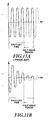
- a triac is used as in the examples shown in Figs. 1 and 10, furthermore, the difference in the gate sensitivity of the triac depending on the trigger mode gives rise to a so-called half-wave period as illustrated in Figs. 11A and 11B before the current is completely shut off. If this half-wave period is too long (such as in excess of 3 seconds), the motor may generate a beat noise or begin to pulsate in its rotary motion.
- the start-up circuit has a start-up thermistor with positive temperature characteristic and a triac connected in series with the auxiliary coil and a triac-controlling thermistor with positive temperature characteristic connected in parallel to the start-up thermistor, and one of the terminals of the triac-controlling thermistor is connected to the gate of the triac.
- the start-up circuit has a triac connected in series with the auxiliary coil and a triac-controlling thermistor with positive temperature characteristic connected in parallel to the auxiliary coil and the triac and one of the terminals of the triac-controlling thermistor is connected to the gate of the triac.
- the triac-controlling thermistor should have resistance 300-3000 ⁇ at 25°C and volume of 30-60mm 3 and its resistance at 25°C should double at 70-125°C.
- An additional resistor may be introduced to the circuit of either embodiment, connecting the gate of the triac with another terminal of the triac on the same side of the triac as the gate.
- the triac-controlling thermistor should have resistance 1000-2000 ⁇ at 25°C and volume of 30-50mm 3 and its resistance value at 25°C should double at 85-110°C.
- the temperature at which the resistance value at 25°C is doubled will be referred to as "the resistance-doubling temperature" and denoted by symbol CP in the figures.
- Fig. 1 was referenced above as describing the structure of a motor-driving circuit incorporating a motor start-up circuit described in Japanese Patent Publication Tokkai 6-339291, it also represents a motor-driving circuit incorporating a motor start-up circuit according to a first embodiment of this invention.
- the circuit according to this invention represented by Fig. 1 is characterized, however, not only as including a triac-controlling PTC thermistor 8 connected in parallel with the start-up PTC thermistor 4 and having one of its terminals connected to the gate G of a triac 7, but also wherein its resistance at 25°C is between 300 and 3000 ⁇ , its volume is between 30 and 60mm 3 and its resistance-doubling temperature is between 70 -125°C.
- the gate current When the switch 5 of this circuit is closed, a current (“the gate current”) will start to flow to the gate G of the triac 7 through the triac-controlling PTC thermistor 8.
- the triac-controlling PTC thermistor 8 is at normal temperature during the start-up period of the motor 1 and since its resistance is still small, this gate current is sufficiently large to switch on the triac 7.
- the triac 7 is triggered every one-half cycle, and a current for starting up the motor 1 flows to the auxiliary coil 2 through the start-up PTC thermistor 4.
- the motor 1 will be herein assumed to be a single-phase induction motor.
- a very weak current will continue to flow through the triac-controlling PTC thermistor 8 thereafter, but since the volume of the triac-controlling PTC thermistor 8 is only 30-60mm 3 , being normally less than one fifth of that of the start-up PTC thermistor 4, the waste in power can also be reduced to less than one fifth. In addition, the return time required until the motor 1 can be restarted can also be reduced significantly.
- the current to the auxiliary coil 2 can be shut off within a period of 1 - 10 seconds as long as the ambient temperature remains between -10 and +100°C.
- the volume of the triac-controlling PTC thermistor 8 is between 30 and 60mm 3 according to this invention.
- the volume of the triac-controlling PTC thermistor 8 and its shut-off time are in positive correlation, that is, the larger the volume, the longer its shut-off time.
- Fig. 2 shows the relationship between the volume and the shut-off time of a triac-controlling PTC thermistor 8, of which the resistance-doubling temperature is 70°C, when the ambient temperature is 100°C (the upper limit of the range of temperature under which the use is contemplated). In general, the heat-up process becomes faster and the heat-up time becomes shorter at higher temperatures.
- Fig. 2 shows that at 100°C the volume of the triac-controlling PTC thermistor 8 must be greater than 30mm 3 because the shut-off time becomes too short and the motor 1 cannot be started up if the volume is less than 30mm 3 .
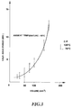
- Fig. 3 shows how the half-wave period changes as the resistance-doubling temperature of the triac-controlling PTC thermistor 8 is changed between 70°C and 125°C when the ambient temperature is -10°C (the lowest limit of the range of temperature under which the use is contemplated). Because the time required to heat up increases with the volume, the half-wave period and the volume are also positively correlated. The half-wave period becomes longer as the ambient temperature drops. At -10°C, if the volume of the triac-controlling PTC thermistor 8 exceeds 60mm 3 , the half-wave period becomes excessively long and the motor will develop beat noise and pulsation in its rotary motion.
- the volume of the triac-controlling PTC thermistor 8 is selected to be within the range of 30 - 60mm 3 . Since the waste in power increases with the volume of the triac-controlling PTC thermistor 8, however, the preferred range is 30 - 50mm 3 .
- the value of the resistance-doubling temperature for the triac-controlling PTC thermistor 8 is within the range of 70 - 125°C according to this invention. Since it takes more time to heat up a PTC thermistor 8 with a higher value of the resistance-doubling temperature, the resistance-doubling temperature and the heat-up time of the PTC thermistor are in positive correlation.
- Fig. 4 shows the relationship between the resistance-doubling temperature and the shut-off time of the triac-controlling PTC thermistor 8 with volume 30mm 3 when the ambient temperature is 100°C. In general, the heat-up time becomes shorter as the ambient temperature increases. When the ambient temperature is 100°C, as shown in Fig. 4, the shut-off time becomes too short and the motor 1 cannot be started up unless the resistance-doubling temperature of the triac-controlling PTC thermistor is greater than 70°C.
- Fig. 5 shows the relationship between the resistance-doubling temperature and the half-wave period of PTC thermistors with volume 30mm 3 to 60mm 3 when the ambient temperature is -10°C.
- the resistance-doubling temperature and the half-wave period are in positive correlation, but the half-wave period becomes too short, as shown in Fig. 5, and the motor develops beat noise and pulsation in its rotary motion if the resistance-doubling temperature of the PTC thermistor exceeds 125°C when the ambient temperature is - 10°C.
- the resistance-doubling temperature of the triac-controlling PTC thermistor 8 is selected to be within the range of 70 - 125°C. Since the waste in power increases as the resistance-doubling temperature becomes higher, it is desirable that the resistance-doubling temperature be lower than 110°C.
- the resistance-doubling temperature of the PTC thermistor 8 is 70°C and its volume is 30mm 3 .
- Fig. 2 shows that the shut-off time can change quite significantly as a result of even a small fluctuation. This can give rise to a failure of the motor to start up.
- the resistance-doubling temperature of the triac-controlling PTC thermistor 8 is preferably higher than 85°C.
- the resistance at 25°C of the triac-controlling PTC thermistor 8 be in the range of 300 - 3000 ⁇ .
- the gate current becomes too large when the voltage of the commercial power source 6 is high, and this may cause a damage to the triac 7. If it is larger than 3000 ⁇ , on the other hand, the gate current becomes too weak when the voltage of the source 6 is low and the triac 7 may fail to be switched on especially at a low ambient temperature.
- a PTC thermistor with resistance at 25°C between 300 ⁇ and 3000 ⁇ is selected. Since the waste in power tends to become low as the resistance at 25°C is increased, a triac-controlling PTC thermistor 8 with resistance greater than 1000 ⁇ at 25°C is preferred. When a triac-controlling PTC thermistor with volume 30 - 60mm 3 is produced, it is preferred to make its resistance at 25°C no greater than 2000 ⁇ from the point of view of limitations such as its specific resistance and shape.
- the volume, the resistance-doubling temperature and the resistance at 25°C thus selected, it is possible even with a small number of components to reliably shut off the current to the auxiliary coil 2 within a normal start-up time of a motor (generally 1 - 10 seconds) and to also reduce the half-wave period under all conditions in the range of ambient temperature between -10 and +100°C.
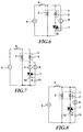
- Fig. 6 shows a motor-driving circuit incorporating another start-up circuit embodying this invention, using the same numerals as used in Fig. 1 to indicate the same or equivalent components.
- the circuit shown in Fig. 6 is characterized in that a triac 7 is connected in series with the auxiliary coil 2, a triac-controlling PTC thermistor 8 being connected in parallel to this series connection of the auxiliary coil 2 and the triac 7 with one of the terminals of this triac-controlling PTC thermistor 8 being connected to the gate of the triac 7.
- a triac-controlling PTC thermistor 8 satisfying the condition that its resistance at 25°C be 300 - 3000 ⁇ , its volume be 30-60mm 3 , and its resistance-doubling temperature be 70 - 125°C.
- the second embodiment of this invention shown in Fig. 6 is advantageous in that the start-up PTC thermistor 4 shown in Fig. 1 can be dispensed with and hence the circuit can be formed with a smaller number of components.
- Fig. 7 shows a motor-driving circuit incorporating still another start-up circuit embodying this invention, using the same numerals as used in Fig. 1 to indicate the same or equivalent components.
- the circuit shown in Fig. 7 is different from that of Fig. 1 only in that an additional resistor 13 is inserted between the gate of the triac 7 and another of its terminals on the side of the gate.
- Fig. 8 shows a motor-driving circuit incorporating still another start-up circuit embodying this invention, using the same numerals as used in Fig. 6 or 7 to indicate the same or equivalent components.
- the circuit shown in Fig. 8 is different from the one shown in Fig. 6 only in that an additional resistor 13 is inserted between the gate of the triac 7 and another of its terminals on the side of the gate.
- the circuits shown in Figs. 7 and 8 are advantageous in that the current flowing to the gate G is reduced because a portion of the current through the triac-controlling PTC thermistor 8 is directed to the additional resistor 13. This is equivalent to increasing the threshold value (the gate trigger current) at which the triac 7 is sure to be switched on. Thus, the shut-off time becomes somewhat shorter as compared to the corresponding circuit (shown in Fig. 1 or 6) without this additional resistor 13. The half-wave period is also thereby shortened. Since this additional resistor 13 serves to reduce the gate current, as explained above, it also serves to prevent damage to the triac 7 when there is a rise in the voltage of the commercial power source 6.
- the resistance at 25°C of the triac-controlling PTC thermistor 8 be 1000 - 2000 ⁇ , its volume be 30 - 50mm 3 , and its resistance-doubling temperature be 85 - 110°C.
Landscapes
- Engineering & Computer Science (AREA)
- Power Engineering (AREA)
- Motor And Converter Starters (AREA)
- Control Of Ac Motors In General (AREA)
- Thermistors And Varistors (AREA)
- Control Of Motors That Do Not Use Commutators (AREA)
- Protection Of Generators And Motors (AREA)
- Valve Device For Special Equipments (AREA)
- Control Of Eletrric Generators (AREA)
Applications Claiming Priority (3)
| Application Number | Priority Date | Filing Date | Title |
|---|---|---|---|
| JP94117/96 | 1996-04-16 | ||
| JP9411796 | 1996-04-16 | ||
| JP8094117A JPH09285168A (ja) | 1996-04-16 | 1996-04-16 | モータ起動用回路 |
Publications (2)
| Publication Number | Publication Date |
|---|---|
| EP0802621A1 true EP0802621A1 (de) | 1997-10-22 |
| EP0802621B1 EP0802621B1 (de) | 1999-06-16 |
Family
ID=14101496
Family Applications (1)
| Application Number | Title | Priority Date | Filing Date |
|---|---|---|---|
| EP97106099A Expired - Lifetime EP0802621B1 (de) | 1996-04-16 | 1997-04-14 | Anlaufschaltung für einen Motor |
Country Status (9)
| Country | Link |
|---|---|
| US (1) | US5898289A (de) |
| EP (1) | EP0802621B1 (de) |
| JP (1) | JPH09285168A (de) |
| KR (1) | KR100255711B1 (de) |
| CN (1) | CN1068732C (de) |
| AT (1) | ATE181470T1 (de) |
| DE (1) | DE69700272T2 (de) |
| DK (1) | DK0802621T3 (de) |
| TW (1) | TW445697B (de) |
Cited By (1)
| Publication number | Priority date | Publication date | Assignee | Title |
|---|---|---|---|---|
| EP2843824A3 (de) * | 2013-08-26 | 2016-01-13 | Sensata Technologies Massachusetts, Inc. | Elektronische Steuerschaltung mit Startfähigkeit |
Families Citing this family (16)
| Publication number | Priority date | Publication date | Assignee | Title |
|---|---|---|---|---|
| US6122153A (en) * | 1999-03-15 | 2000-09-19 | Eaton Corporation | Temperature protection control for a motor starter |
| MY125213A (en) * | 1999-11-12 | 2006-07-31 | Lg Electronics Inc | "device and method for controlling supply of current and static capacitance to compressor" |
| BRPI0015643B1 (pt) * | 1999-11-12 | 2015-06-09 | Lg Electronics Inc | Dispositivo e um método para controlar a alimentação de uma capacitância estática e de uma corrente para compressores |
| US7018416B2 (en) * | 2000-07-06 | 2006-03-28 | Zimmer Spine, Inc. | Bone implants and methods |
| US6570359B2 (en) | 2000-07-15 | 2003-05-27 | Umakant Dipa Dubhashi | Motor starting circuit |
| JP4097034B2 (ja) * | 2004-02-24 | 2008-06-04 | 株式会社センサータ・テクノロジーズジャパン | 省電力化モータ起動装置 |
| JP4792826B2 (ja) * | 2004-07-23 | 2011-10-12 | 株式会社村田製作所 | 単相誘導モータの起動回路 |
| CN1294694C (zh) * | 2004-11-24 | 2007-01-10 | 常熟市天银机电有限公司 | 互感式无触点起动器 |
| WO2007043750A1 (en) * | 2005-10-07 | 2007-04-19 | Lg Electronics Inc. | Power saving type compressor and refrigerator with the same and method for controlling the same |
| DE102006021256A1 (de) | 2006-04-28 | 2007-11-08 | Danfoss Compressors Gmbh | Motorstartschaltkreis |
| DE102006034499A1 (de) | 2006-07-19 | 2008-01-31 | Danfoss Compressors Gmbh | Motorstartschaltkreis |
| DE102006053524B4 (de) | 2006-11-07 | 2011-05-26 | Danfoss Flensburg Gmbh | Motorstartschaltkreis |
| KR101322316B1 (ko) * | 2007-05-10 | 2013-10-25 | 엘지전자 주식회사 | 냉장고용 모터의 기동제어장치 및 방법 |
| CN101800503B (zh) * | 2010-02-08 | 2011-06-15 | 杭州星帅尔电器有限公司 | 一种制冷压缩机用电子式起动器 |
| KR101301518B1 (ko) * | 2012-06-22 | 2013-09-04 | 김영준 | 아크없는 개폐기 및 보호기능을 포함한 삼상 전동기용 기동 회로 |
| CN102969945B (zh) * | 2012-12-10 | 2015-07-15 | 森萨塔科技(常州)有限公司 | 正温度系数热敏电阻启动器 |
Citations (5)
| Publication number | Priority date | Publication date | Assignee | Title |
|---|---|---|---|---|
| US3683250A (en) * | 1970-07-29 | 1972-08-08 | Ecc Corp | Timed induction motor start switch utilizing positive temperature coefficient thermistor and semi-conductor switching device |
| US4267635A (en) * | 1976-05-03 | 1981-05-19 | Texas Instruments Incorporated | Method of making a solid state electrical switch |
| JPH06339291A (ja) * | 1992-12-05 | 1994-12-06 | Yamada Denki Seizo Kk | 単相誘導電動機の起動装置 |
| JPH06349603A (ja) * | 1993-06-04 | 1994-12-22 | Murata Mfg Co Ltd | 消磁回路用正特性サーミスタ |
| JPH07123759A (ja) * | 1993-10-25 | 1995-05-12 | Yamada Denki Seizo Kk | 単相誘導電動機の起動装置 |
Family Cites Families (8)
| Publication number | Priority date | Publication date | Assignee | Title |
|---|---|---|---|---|
| DE1613734B2 (de) * | 1967-10-07 | 1971-12-02 | Danfoss A/S, Nordborg (Dänemark) | Uebertemperaturschutz fuer die wicklung von wechselstrommo toren |
| US3544869A (en) * | 1968-12-30 | 1970-12-01 | Texas Instruments Inc | A.c. motor starting control circuit utilizing triggerable semiconductor switching device with thermistor in gating circuit |
| US3965392A (en) * | 1974-01-02 | 1976-06-22 | Sprague Electric Company | Motor start system with two dissimilar PTCR elements |
| US4161681A (en) * | 1977-03-17 | 1979-07-17 | General Electric Company | Prime mover, method of operating such and circuit |
| DE3021689A1 (de) * | 1980-06-10 | 1981-12-17 | Metabowerke GmbH & Co, 7440 Nürtingen | Ueberlastsicherung fuer den motor, insbesondere eines elektrohandwerkzeugs |
| JPS6339291A (ja) * | 1986-08-04 | 1988-02-19 | Sony Corp | 衛星放送受信機 |
| CA2085202C (en) * | 1992-03-24 | 1996-10-22 | Ricky L. Bunch | Positive temperature coefficient start winding protection |
| JPH05328767A (ja) * | 1992-05-25 | 1993-12-10 | Murata Mfg Co Ltd | 単相交流誘導モーターの起動回路 |
-
1996
- 1996-04-16 JP JP8094117A patent/JPH09285168A/ja active Pending
-
1997
- 1997-04-01 US US08/831,992 patent/US5898289A/en not_active Expired - Lifetime
- 1997-04-08 TW TW086104407A patent/TW445697B/zh not_active IP Right Cessation
- 1997-04-14 EP EP97106099A patent/EP0802621B1/de not_active Expired - Lifetime
- 1997-04-14 DK DK97106099T patent/DK0802621T3/da active
- 1997-04-14 AT AT97106099T patent/ATE181470T1/de active
- 1997-04-14 DE DE69700272T patent/DE69700272T2/de not_active Expired - Lifetime
- 1997-04-16 CN CN97110755A patent/CN1068732C/zh not_active Expired - Lifetime
- 1997-04-16 KR KR1019970013936A patent/KR100255711B1/ko not_active Expired - Lifetime
Patent Citations (6)
| Publication number | Priority date | Publication date | Assignee | Title |
|---|---|---|---|---|
| US3683250A (en) * | 1970-07-29 | 1972-08-08 | Ecc Corp | Timed induction motor start switch utilizing positive temperature coefficient thermistor and semi-conductor switching device |
| US4267635A (en) * | 1976-05-03 | 1981-05-19 | Texas Instruments Incorporated | Method of making a solid state electrical switch |
| JPH06339291A (ja) * | 1992-12-05 | 1994-12-06 | Yamada Denki Seizo Kk | 単相誘導電動機の起動装置 |
| US5451853A (en) * | 1992-12-05 | 1995-09-19 | Yamada Electric Mfg. Co., Ltd. | Starting device for a single phase induction motor |
| JPH06349603A (ja) * | 1993-06-04 | 1994-12-22 | Murata Mfg Co Ltd | 消磁回路用正特性サーミスタ |
| JPH07123759A (ja) * | 1993-10-25 | 1995-05-12 | Yamada Denki Seizo Kk | 単相誘導電動機の起動装置 |
Non-Patent Citations (2)
| Title |
|---|
| PATENT ABSTRACTS OF JAPAN vol. 95, no. 3 28 April 1995 (1995-04-28) * |
| PATENT ABSTRACTS OF JAPAN vol. 95, no. 8 29 September 1995 (1995-09-29) * |
Cited By (1)
| Publication number | Priority date | Publication date | Assignee | Title |
|---|---|---|---|---|
| EP2843824A3 (de) * | 2013-08-26 | 2016-01-13 | Sensata Technologies Massachusetts, Inc. | Elektronische Steuerschaltung mit Startfähigkeit |
Also Published As
| Publication number | Publication date |
|---|---|
| DK0802621T3 (da) | 1999-11-22 |
| CN1168022A (zh) | 1997-12-17 |
| EP0802621B1 (de) | 1999-06-16 |
| TW445697B (en) | 2001-07-11 |
| KR970072623A (ko) | 1997-11-07 |
| ATE181470T1 (de) | 1999-07-15 |
| KR100255711B1 (ko) | 2000-05-01 |
| DE69700272D1 (de) | 1999-07-22 |
| DE69700272T2 (de) | 2000-01-05 |
| CN1068732C (zh) | 2001-07-18 |
| JPH09285168A (ja) | 1997-10-31 |
| US5898289A (en) | 1999-04-27 |
Similar Documents
| Publication | Publication Date | Title |
|---|---|---|
| US5898289A (en) | Motor start-up circuit with a triac and PTC thermistors | |
| EP0571956B1 (de) | Anlassschaltung für einen Einphasen-Induktionsmotor | |
| JP3272493B2 (ja) | 単相誘導電動機の起動装置 | |
| KR101114096B1 (ko) | 소비 전력이 저감된 모터 시동 장치 | |
| KR100196639B1 (ko) | 단상 유도 전동기의 기동용 전자회로 | |
| US4066937A (en) | Control circuit for a two speed single phase motor | |
| US7498763B2 (en) | Apparatus and method for reducing the current drawn during starting of a single-phase AC asynchronous motor | |
| US3737752A (en) | Motor control system | |
| US5428493A (en) | Motor starting relay device having PTC thermistors | |
| US5617001A (en) | A.C. motor starting control circuit utilizing triggerable semiconductor switching device | |
| EP2194640B1 (de) | Starter für Schwachstromelektromotor | |
| JPH0638467A (ja) | 単相誘導電動機の起動装置 | |
| US6788023B2 (en) | Motor starter circuit, particularly for refrigerator compressors | |
| US4320309A (en) | Oscillatory circuit utilizing PTC resistor | |
| JPH06319282A (ja) | 単相誘導電動機の起動回路 | |
| JP4752105B2 (ja) | 単相交流誘導モータの起動回路 | |
| JP3292877B2 (ja) | 単相誘導電動機の起動装置 | |
| KR880000671B1 (ko) | 냉장고 압축기의 제어장치 | |
| JP2578817Y2 (ja) | モータ始動回路 | |
| JPH05244787A (ja) | 単相交流誘導モーターの起動回路 | |
| SU1753567A1 (ru) | Электропривод | |
| GB2292645A (en) | Starter for single phase motor | |
| JPH0878152A (ja) | マグネトロン駆動回路 | |
| CZ9026U1 (cs) | Zapojení pro omezení záběrového proudu motoru při jeho zapnutí | |
| JPS5932373A (ja) | 単相誘導電動機の運転回路 |
Legal Events
| Date | Code | Title | Description |
|---|---|---|---|
| PUAI | Public reference made under article 153(3) epc to a published international application that has entered the european phase |
Free format text: ORIGINAL CODE: 0009012 |
|
| 17P | Request for examination filed |
Effective date: 19970414 |
|
| AK | Designated contracting states |
Kind code of ref document: A1 Designated state(s): AT DE DK IT NL |
|
| 17Q | First examination report despatched |
Effective date: 19970113 |
|
| GRAG | Despatch of communication of intention to grant |
Free format text: ORIGINAL CODE: EPIDOS AGRA |
|
| GRAG | Despatch of communication of intention to grant |
Free format text: ORIGINAL CODE: EPIDOS AGRA |
|
| GRAH | Despatch of communication of intention to grant a patent |
Free format text: ORIGINAL CODE: EPIDOS IGRA |
|
| GRAH | Despatch of communication of intention to grant a patent |
Free format text: ORIGINAL CODE: EPIDOS IGRA |
|
| GRAA | (expected) grant |
Free format text: ORIGINAL CODE: 0009210 |
|
| AK | Designated contracting states |
Kind code of ref document: B1 Designated state(s): AT DE DK IT NL |
|
| REF | Corresponds to: |
Ref document number: 181470 Country of ref document: AT Date of ref document: 19990715 Kind code of ref document: T |
|
| REF | Corresponds to: |
Ref document number: 69700272 Country of ref document: DE Date of ref document: 19990722 |
|
| REG | Reference to a national code |
Ref country code: DK Ref legal event code: T3 |
|
| PLBE | No opposition filed within time limit |
Free format text: ORIGINAL CODE: 0009261 |
|
| STAA | Information on the status of an ep patent application or granted ep patent |
Free format text: STATUS: NO OPPOSITION FILED WITHIN TIME LIMIT |
|
| 26N | No opposition filed | ||
| PGFP | Annual fee paid to national office [announced via postgrant information from national office to epo] |
Ref country code: NL Payment date: 20160420 Year of fee payment: 20 |
|
| PGFP | Annual fee paid to national office [announced via postgrant information from national office to epo] |
Ref country code: DE Payment date: 20160421 Year of fee payment: 20 |
|
| PGFP | Annual fee paid to national office [announced via postgrant information from national office to epo] |
Ref country code: AT Payment date: 20160421 Year of fee payment: 20 Ref country code: DK Payment date: 20160420 Year of fee payment: 20 Ref country code: IT Payment date: 20160427 Year of fee payment: 20 |
|
| REG | Reference to a national code |
Ref country code: DE Ref legal event code: R071 Ref document number: 69700272 Country of ref document: DE |
|
| REG | Reference to a national code |
Ref country code: DK Ref legal event code: EUP Effective date: 20170414 |
|
| REG | Reference to a national code |
Ref country code: NL Ref legal event code: MK Effective date: 20170413 |
|
| REG | Reference to a national code |
Ref country code: AT Ref legal event code: MK07 Ref document number: 181470 Country of ref document: AT Kind code of ref document: T Effective date: 20170414 |