EP0802554A2 - Dispositif pour verrouiller un couvercle à un châssis d'un interrupteur - Google Patents
Dispositif pour verrouiller un couvercle à un châssis d'un interrupteur Download PDFInfo
- Publication number
- EP0802554A2 EP0802554A2 EP97102388A EP97102388A EP0802554A2 EP 0802554 A2 EP0802554 A2 EP 0802554A2 EP 97102388 A EP97102388 A EP 97102388A EP 97102388 A EP97102388 A EP 97102388A EP 0802554 A2 EP0802554 A2 EP 0802554A2
- Authority
- EP
- European Patent Office
- Prior art keywords
- cover
- sliding window
- sealing
- sealing tab
- opening
- Prior art date
- Legal status (The legal status is an assumption and is not a legal conclusion. Google has not performed a legal analysis and makes no representation as to the accuracy of the status listed.)
- Granted
Links
Images


Classifications
-
- H—ELECTRICITY
- H01—ELECTRIC ELEMENTS
- H01H—ELECTRIC SWITCHES; RELAYS; SELECTORS; EMERGENCY PROTECTIVE DEVICES
- H01H85/00—Protective devices in which the current flows through a part of fusible material and this current is interrupted by displacement of the fusible material when this current becomes excessive
- H01H85/02—Details
- H01H85/24—Means for preventing insertion of incorrect fuse
-
- H—ELECTRICITY
- H01—ELECTRIC ELEMENTS
- H01H—ELECTRIC SWITCHES; RELAYS; SELECTORS; EMERGENCY PROTECTIVE DEVICES
- H01H31/00—Air-break switches for high tension without arc-extinguishing or arc-preventing means
- H01H31/02—Details
- H01H31/12—Adaptation for built-in fuse
- H01H31/122—Fuses mounted on, or constituting the movable contact parts of, the switch
-
- H—ELECTRICITY
- H01—ELECTRIC ELEMENTS
- H01H—ELECTRIC SWITCHES; RELAYS; SELECTORS; EMERGENCY PROTECTIVE DEVICES
- H01H85/00—Protective devices in which the current flows through a part of fusible material and this current is interrupted by displacement of the fusible material when this current becomes excessive
- H01H85/02—Details
- H01H85/30—Means for indicating condition of fuse structurally associated with the fuse
Definitions
- the invention relates to a device for securing a cover to a base part of a NH fuse switch disconnector, which has a switch frame, contact springs and a protective cover, by sealing and / or locking, in which fuse links are arranged next to one another on the cover transversely to their longitudinal direction and are separated from one another by at least one phase partition and in which the front wall of the cover in the area of the fuse link has a recess covered by a sliding window with test holes.
- Devices of the above type are often arranged in front of or behind meters because of the There is a desire not to have the lid of such devices easily opened by laypersons or by other end users. In every house there are electrical devices, the lids of which are sealed.
- fuse links are held in the cover in a similar manner as described above.
- the contact is closed by closing the cover.
- the phases R, S and T are generally located as three fuse links one above the other in the case of safety edges or next to one another in the case of switch disconnectors.
- the front wall of the cover facing the user or viewer has viewing windows which make it possible to recognize the operating state (defective or in order) from the outside.
- the safest construction of this type provides viewing windows which are inserted into the front wall of the lid such that access to any elements of the live device from the outside is not possible without opening the lid.
- NH fuse switch disconnectors which have test holes in the viewing window, which is guided between a closed position and a test position such that the respective hole in the closed position of the window is closed by a cover or housing part and is in the test position of the Washer is open over the relevant device element, for example over the contact blade of a fuse link.
- the viewing window can be moved from a closed to a test position and back. In the test position, the user can use the test pin to access the relevant device element, for example the grip tab of a fuse link. Movement of the sliding window is understood to mean translatory or rotary sliding or turning from one position to the other.
- the object of the invention is therefore to design the device of the type mentioned in such a way that, in addition to the cover, the sliding window can also be secured and / or locked against unwanted movements by a simple mechanism.
- a first sealing tab is attached to the base part of the circuit breaker, which protrudes transversely to the longitudinal and transverse directions to the front (third direction) through an opening on the front surface of the cover, and that one on the sliding window second sealing tab attached and movable with the sliding window and can be brought into alignment with the first sealing tab.
- both the sliding window fixed in a certain way and the lid (closed) located in a certain position can be defined and secured and / or locked by sealing in one operation so that neither the lid nor the sliding window are moved in an undesired manner .
- the NH fuse switch of the type considered here can be improved by the invention in the same way as an NH fuse block. Both devices are used to switch a consumer on or off using these switches.
- the cover which can be swiveled out relative to the switch frame and swiveled back to it, carries the fuse links for these switches, which are arranged next to each other, for example, one insert for each phase (R, S, T). Hanging parts are therefore provided on the lids for holding tabs on the fuse links.
- the longitudinal direction of the fuse links is the connecting line of the two opposite contact blades. While one arranges the fuse links one behind the other in a load disconnector strip, a switch disconnector is assumed here to illustrate the invention, in which the fuse links are arranged side by side in the above-mentioned transverse direction.
- the third direction mentioned is approximately vertical both in the longitudinal and in the transverse direction. To explain the invention, it is assumed that an observer looks almost perpendicularly from the front onto the front wall of the cover, while a fastening wall, for example a cabinet wall, is located behind it.
- the measures according to the invention can also be used to lock, for example, that a locking pin, a locking bolt or a padlock is inserted through recesses or holes in the sealing tabs brought into alignment in front of the front surface of the cover. This means that you can also ensure a mechanically firm lock and protect the inside of the switch disconnector against unauthorized, willful opening.
- the base part mentioned in the explanation corresponds to the switch frame of a switch disconnector, including partition walls, contact springs and a protective cover, in particular a contact cover.
- Other parts can of course also be attached or arranged on the base part, but the parts and elements mentioned above that are firmly anchored to the switch frame and to which the first sealing tab is fastened are of particular interest for the invention.
- the front surface of the lid is, so to speak, the skin that could be placed on the lid from the front.
- the front surface is thus formed by the front wall of the cover, which is preferably frame-shaped and surrounds the sliding window, the sliding window itself and optionally the handle at the top.
- the sealing tab must protrude through this front surface, so that it becomes accessible to the viewer and user and sealing and / or locking is possible.
- the first sealing tab is attached to at least one side wall of the switch frame and the opening is arranged in the front wall of the cover in the edge region of the sliding window.
- the first sealing tab attached to the side wall of the switch frame extends forward in the third direction mentioned, against the viewing direction of the viewer.
- the sealing tab protrudes forward through the front wall of the cover and can be fixed in this position by a seal in such a way that the cover cannot be pivoted so far out of the switch frame without damaging the seal (the sealing wire) that the contact knife of a fuse link can be detached from the contact spring.
- a sealing wire can be inserted through the eyelet or the sealing hole of the first sealing tab, it protrudes up to the front surface of the front cover wall.
- the opening mentioned is arranged in the latter.
- a locking pin, a padlock or the like through the eyelet or the sealing hole of at least one and preferably both sealing tabs.
- this opening is arranged in the front wall of the lid at the edge of the sliding window in question.
- a first sealing tab can be attached to both side walls of the switch frame or to an intermediate wall.
- a single sealing tab of the first type is sufficient because the cover cannot be pivoted out of the switch frame undesirably and unrecognized.
- a second sealing tab namely the sealing tab of the sliding window
- the second sealing tab is attached to the sliding window and can be moved with it, securing a certain position of the sliding window can be achieved simultaneously with securing the cover in its closed position.
- the second sealing tab is positioned so that in the operating position of the disconnector, in which testing through the test holes is excluded, the second sealing tab can be aligned with the first.
- the sealing wire can then advantageously be inserted through both tabs, and this in front of the front surface of the lid front wall. A simple mechanism prevents the unwanted movement of both the cover and the sliding window.
- the first sealing tab is fastened to the protective cover which is firmly connected to the switch frame.
- the first sealing tab is fastened to at least one phase partition and projects forward through the opening in the sliding window, which is designed as a longitudinal slot.
- the opening in the front cover wall adjoins the outer edge of the sliding window and is spaced from the side wall of the switch frame.
- the first sealing tab is formed like a flat web or an essentially flat plate, this is particularly preferably arranged parallel to the plane of the side wall of the switch frame.
- the opening which is preferably rectangular and whose longitudinal direction extends parallel to the side wall of the switch frame, adjoins the outer edge of the sliding window for the passage of the first sealing tab, i.e. is arranged close to this.
- distances of 0.5-3 mm, preferably 1-2 mm are sufficient to create a sufficiently large opening which, on the other hand, requires as little installation space in the transverse direction as possible.
- the sealing hole of the sealing tab in the closed state of the cover adjoins the front surface of the front cover wall or the sliding window.
- the front end of the sealing tab which is closest to the viewer of the switch frame, is designed in the manner of an eyelet with the sealing hole mentioned. It is sufficient if after the measure according to the invention mentioned only the eyelet with the sealing hole protrudes from the opening described above in the front wall of the cover. The same applies to the second sealing tab on the sliding window, which also has an eyelet with a sealing hole towards the viewer (in the third direction). If the edge of the respective sealing hole is now essentially flush with the mentioned front surface of the front cover or the sliding window, the user can carry out the sealing, i.e.
- the lid and the sliding window by inserting the sealing wire through both sealing tabs when the lid is closed.
- the sliding window is then automatically in the operating position of the device, which can also be called the protective position.
- the test holes are covered, for example by device parts located in the lid behind its front wall.
- the lid front wall can also be provided with a depression in the area of the opening. Then the first sealing tab protrudes so far over the front surface of the front cover wall that the sealing hole is free for the passage of a sealing wire, nevertheless the sealing tab can be set back through the trough relative to the front level of the front cover wall.
- the side wall of the cover can also be removed, if necessary, in order to make protruding parts accessible to tools, without enlarging the entire outer contour of the switch disconnector. Such disconnectors can be arranged side by side without hindering the assembly.
- first sealing tab is formed in one piece with the side wall of the switch frame.
- second sealing tab can also be configured in one piece with the sliding window.
- the switch frame and / or cover are in many cases made of plastic, with parts being molded by injection molding. Devices constructed in this way are inexpensive to manufacture and comply with the relevant technical regulations.
- a cover and a sliding window on the base part in particular on the switch frame or the cover, can be secured and / or locked and sealed or fixed by a simple mechanism in such a way that a single sealing wire, locking pin or a padlock is in alignment sealing holes lying to one another are guided and secured.
- an additional closing device is not required for the invention. In this way, an elegant, compact and little space-consuming solution for a sealing and / or locking device has been found.
- the securing insert generally designated 1 in the embodiment shown here, is fastened to the cover 6 via a grip tab 2 in the suspension parts 4 forming an insertion slot 3.
- the suspension parts 4 in the cover 6 are the suspension parts 4 in the cover 6.
- the front cover 8 is closed at the front by a sliding window 9, in which test holes 10 are provided at the top and bottom for the voltage test.
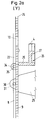
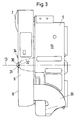
- the dash-dotted line 11 in FIG. 4 extends upward and downward, which represents the longitudinal direction of the fuse links 1 not shown in FIG. 4 but visible in FIG. Right across, i.e. in FIG. 4 in the horizontal direction, the dash-dotted line 12 which represents the transverse direction runs, while in FIG. 3 the horizontal dash-dotted line 13 is the third direction which, for example, for the viewer when he looks from left to right in FIG Looking direction.
- three fuse links 1 lie side by side in the transverse direction 12. They are hung with their handle straps (Figure 1) with the lid 6 open in the upper or lower insertion slot 3 between the hanging parts 4.
- the contact blades 14 and 14 ' can be seen in FIG. If you put an imaginary dash-dotted line 11 in the connecting line of the two contact blades 14, 14 ', then this line 11 lies in the longitudinal direction, which is the vertical in the embodiment shown here.
- the handle tab 2 of the fuse link 1 is perpendicular to it in a known manner, in the representation of the embodiment shown here in the horizontal.
- Figure 1 one looks at the rear or left side wall 15 of the switch frame 5, and in the side view according to Figure 3 one looks at the front or right side wall 16.
- the side walls 15 and 16 lie parallel to a plane which is from the longitudinal direction 11 and the third direction 13 is spanned.
- the switch frame 5 also has phase partitions 18 which extend up to the vicinity of the handle 7 between the fuse inserts not shown in FIG. Around the pivot point 19 (FIG. 1), the cover 6 can be pivoted out into the open position (not shown in the drawings) with the aid of the bearing guide 20 by moving the handle 7 in FIG. 1 to the left and in FIG. 4 towards the viewer pulls.
- the switch frame 5 is attached via mounting holes 21 for mounting the base plate on a base plate, not shown, for example on the plate of a cabinet.
- FIG. 2a the upper part of the cover front wall is according to the detail Y shown in Figure 1.
- “front” is left and “rear” right, because the viewer looks perpendicularly at the paper plane of FIG. 4 and thus from left to right in FIGS. 1-3.
- a large, almost square recess 22, which is delimited by its edge 23, can be seen in the viewing direction.
- the sliding window 9 is somewhat larger with its outer dimensions than the recess 22 and has an edge 24 which runs around the sliding window 9 in a rectangular manner.
- FIG. 1 It can be seen from the cross-sectional illustration in FIG. 1 how the sliding window 9 covers the latter in both sliding positions due to its larger configuration than the recess 22.
- a test device can be inserted through the test opening 10 to the contact knife 14 from left to right into the interior of the cover and the switch frame 5, for example to test a voltage.
- the lower edge 24 of the sliding window 9 is offset further downward, with the result that the lower test hole 10 disappears behind the lower part of the front wall 8 of the cover 6 and is covered by it.
- the upper test hole 10 is also covered, so to speak, because, according to the illustration in FIG. 2b, in no case does it allow access to the contact knife 14.
- a bar 27 stands vertically to form the guide angle 26.
- the suspension parts 4 are attached above it.
- a first sealing tab 29 is integrally formed on the left side wall 15 of the switch frame 5 via a support 28 (FIGS. 4 and 5) extending in the transverse direction 12 over the distance of 4 mm from the side wall 15.
- This has the shape of a substantially flat plate, which extends parallel to the plane of the side wall 15 of the switch frame 5, in the third direction 13, i.e. towards the viewer.
- the viewer looks at the front end 30 of the first sealing tab 29, which is designed like an eyelet and defines a sealing hole 31.
- This sealing hole 31 adjoins the front surface of the lid front wall 8, as can be seen in the side view in FIG. 3, namely with the aid of a trough or trough-like recess 32.
- the edge of the sealing hole 31 lies flush and adjacent to the surface of the sliding window 9, which is equivalent in the area of the window of the front cover 8.
- the first sealing tab 29 can protrude with its front end 30 from the area behind the front cover 8 to the front, there is an opening 33 in the front wall 8 of the cover 6.
- the Opening 33 is located in the region of the edge 24 of the sliding window 9. More specifically, the opening 33, viewed in the direction of view (third direction 13), borders on the outer edge 24 of the sliding window 9.
- the left vertical edge of the recess 22 shown in FIGS. 4 and 5 is gradually withdrawn towards the side wall 15 in order to form the opening 33 in the front wall 8 of the lid in this way.
- the U is open in the direction of the opposite right side wall 16 of the switch frame 5, i.e. inwards (to the right in FIGS. 4 and 5).
- the opening 33 is delimited by the vertical left edge 24 of the sliding window 9.
- the opening 33 is rectangular and dimensioned so that the first sealing tab 29 can be inserted; in the inserted state, therefore, has just space in the opening 33.
- the length of the rectangular opening 33 is somewhat longer than the width of the first sealing tab 29 in the area next to the sealing hole 31.
- FIGS. 1-3 also show a second sealing tab 34 with a sealing hole 35.
- both sealing holes 31 and 35 are in alignment with one another, which is why the circle shown there denotes both reference numbers 31 and 35 is.
- This is the protective or operating state in which the position of the test holes 10 does not allow contact with live parts, such as the contact blades 14, 14 '. If you lead a sealing wire through the sealing holes 31, 35 according to FIG. 2b, then both the cover in its closed position and the sliding window 9 are secured in their protective position and can be sealed.
Landscapes
- Switch Cases, Indication, And Locking (AREA)
- Push-Button Switches (AREA)
- Driving Mechanisms And Operating Circuits Of Arc-Extinguishing High-Tension Switches (AREA)
- Fuses (AREA)
Priority Applications (1)
| Application Number | Priority Date | Filing Date | Title |
|---|---|---|---|
| SI9730281T SI0802554T1 (en) | 1996-04-20 | 1997-02-14 | Device for locking a cover to a switch framework |
Applications Claiming Priority (2)
| Application Number | Priority Date | Filing Date | Title |
|---|---|---|---|
| DE19615859A DE19615859B4 (de) | 1996-04-20 | 1996-04-20 | Einrichtung zum Sichern eines Deckels an einem Schaltergestell |
| DE19615859 | 1996-04-20 |
Publications (3)
| Publication Number | Publication Date |
|---|---|
| EP0802554A2 true EP0802554A2 (fr) | 1997-10-22 |
| EP0802554A3 EP0802554A3 (fr) | 1998-01-28 |
| EP0802554B1 EP0802554B1 (fr) | 2001-11-14 |
Family
ID=7791996
Family Applications (1)
| Application Number | Title | Priority Date | Filing Date |
|---|---|---|---|
| EP97102388A Expired - Lifetime EP0802554B1 (fr) | 1996-04-20 | 1997-02-14 | Dispositif pour verrouiller un couvercle à un châssis d'un interrupteur |
Country Status (5)
| Country | Link |
|---|---|
| EP (1) | EP0802554B1 (fr) |
| AT (1) | ATE208957T1 (fr) |
| DE (2) | DE19615859B4 (fr) |
| PL (1) | PL182448B1 (fr) |
| SI (1) | SI0802554T1 (fr) |
Cited By (3)
| Publication number | Priority date | Publication date | Assignee | Title |
|---|---|---|---|---|
| EP1775745A1 (fr) * | 2005-10-11 | 2007-04-18 | Pronutec, S.A. | Porte fusible avec dispositif de retenue extern |
| EP2790202A1 (fr) * | 2013-04-12 | 2014-10-15 | Jean Müller GmbH Elektrotechnische Fabrik | Dispositif de commutation de sécurité haute puissance basse tension |
| EP2849191A1 (fr) * | 2013-09-11 | 2015-03-18 | Apator S.A. | Disjoncteur de sécurité doté d'une ouverture d'accès dans une unité de couvercle |
Families Citing this family (3)
| Publication number | Priority date | Publication date | Assignee | Title |
|---|---|---|---|---|
| DE19715264B4 (de) * | 1997-04-12 | 2006-06-29 | Efen Gmbh | Einrichtung zum Plombieren und Verriegeln des Deckels eines Sicherungsschaltgerätes |
| DE102005017672A1 (de) * | 2005-04-11 | 2006-10-12 | Siemens Ag | Sicherungslasttrennschalter |
| DE102012223656B3 (de) | 2012-12-18 | 2014-04-03 | Wöhner GmbH & Co. KG Elektrotechnische Systeme | Mehrpoliges Schaltgerät |
Family Cites Families (2)
| Publication number | Priority date | Publication date | Assignee | Title |
|---|---|---|---|---|
| DE1136396B (de) * | 1958-03-01 | 1962-09-13 | Geyer Fa Christian | Anschlusskasten aus Isolierstoff, insbesondere Kabel-Hausanschlusskasten |
| DE3639669C2 (de) * | 1986-11-20 | 1993-12-23 | Efen Elektrotech Fab | Niederspannungs-Hochleistungs- Sicherungsschaltgerät mit Fensteranordnung |
-
1996
- 1996-04-20 DE DE19615859A patent/DE19615859B4/de not_active Expired - Fee Related
-
1997
- 1997-02-14 EP EP97102388A patent/EP0802554B1/fr not_active Expired - Lifetime
- 1997-02-14 DE DE59705325T patent/DE59705325D1/de not_active Expired - Lifetime
- 1997-02-14 SI SI9730281T patent/SI0802554T1/xx unknown
- 1997-02-14 AT AT97102388T patent/ATE208957T1/de not_active IP Right Cessation
- 1997-04-18 PL PL97319550A patent/PL182448B1/pl not_active IP Right Cessation
Cited By (3)
| Publication number | Priority date | Publication date | Assignee | Title |
|---|---|---|---|---|
| EP1775745A1 (fr) * | 2005-10-11 | 2007-04-18 | Pronutec, S.A. | Porte fusible avec dispositif de retenue extern |
| EP2790202A1 (fr) * | 2013-04-12 | 2014-10-15 | Jean Müller GmbH Elektrotechnische Fabrik | Dispositif de commutation de sécurité haute puissance basse tension |
| EP2849191A1 (fr) * | 2013-09-11 | 2015-03-18 | Apator S.A. | Disjoncteur de sécurité doté d'une ouverture d'accès dans une unité de couvercle |
Also Published As
| Publication number | Publication date |
|---|---|
| PL182448B1 (pl) | 2002-01-31 |
| PL319550A1 (en) | 1997-10-27 |
| EP0802554B1 (fr) | 2001-11-14 |
| DE19615859B4 (de) | 2005-05-25 |
| SI0802554T1 (en) | 2002-06-30 |
| ATE208957T1 (de) | 2001-11-15 |
| DE19615859A1 (de) | 1997-10-23 |
| EP0802554A3 (fr) | 1998-01-28 |
| DE59705325D1 (de) | 2001-12-20 |
Similar Documents
| Publication | Publication Date | Title |
|---|---|---|
| EP0561293B1 (fr) | Couvercle pour la face frontale d'appareils de commutation électriques à commande d'un levier oscillant, en particulier pour disjoncteurs de puissance à basse tension | |
| DE69600047T2 (de) | Zusammensetzbare elektrische Schnittstellenvorrichtung | |
| DE3833032A1 (de) | Anschlussdose fuer fernsprech-apparate und/oder fernsprech-zusatzgeraete | |
| EP0600108A1 (fr) | Canal de coin pour câble | |
| DE69836025T2 (de) | Kupplungsvorrichtung zwischen zwei modularen elektrischen element | |
| DE3786353T2 (de) | Verbindungsvorrichtung. | |
| DE69602066T2 (de) | Elektrisches Gerät mit Anschlussklemmen, die durch eine Blende mit Flügeln geschützt sind | |
| DE3021637A1 (de) | Schliessvorrichtung fuer eine tuer | |
| DE2824216A1 (de) | Betaetigungsvorrichtung fuer einen tuerverschluss, insbesondere innenbetaetigungsvorrichtung fuer einen kraftfahrzeug-tuerverschluss | |
| EP0802554B1 (fr) | Dispositif pour verrouiller un couvercle à un châssis d'un interrupteur | |
| AT394284B (de) | Sicherheitslastschaltleiste (einbauleiste) | |
| DE20114905U1 (de) | Haltevorrichtung der Klemmbereiche eines flexiblen Bandleiters in einem Steckverbinder und so ausgerüsteter Steckverbinder | |
| EP0123788A2 (fr) | Appareil d'installation électrique | |
| DE4207156A1 (de) | Konstruktion eines elektrischen schalters und eines sicherungshalters | |
| DE102008016648A1 (de) | Lasttrennschalter | |
| DE3943377C1 (en) | Locking closure for electrical switching appts. housing - has arresting nose on cover engaging recess in housing and locking part arresting snap coupling | |
| DE68901818T2 (de) | Abgedichtetes gehaeuse, insbesondere fuer elektrische oder elektronische baugruppen. | |
| EP0508291B1 (fr) | Dispositif de coupe-circuit NH-fusible du type baguette | |
| DE663635C (de) | Kasten fuer gekapselte, insbesondere isolierstoffgekapselte elektrische Schalt- und Verteilungsanlagen | |
| EP2428974B1 (fr) | Sectionneur de sécurité électrique doté d'un couvercle de contacteur mobile | |
| DE102006050700B4 (de) | Zähler- und Verteilerschrank | |
| EP0802551B1 (fr) | Dispositif de verrouillage pour cartouches à fusibles dans un sectionneur | |
| DE69808836T2 (de) | Adapter zur modularen Verbindung elektrischer Geräte zu einem elektrischen Verteilungssystem auf Basis von Schiene | |
| DE10109091A1 (de) | NH-Sicherungsschaltgerät | |
| EP3787135A1 (fr) | Armoire de distribution |
Legal Events
| Date | Code | Title | Description |
|---|---|---|---|
| PUAI | Public reference made under article 153(3) epc to a published international application that has entered the european phase |
Free format text: ORIGINAL CODE: 0009012 |
|
| AK | Designated contracting states |
Kind code of ref document: A2 Designated state(s): AT BE CH DE LI |
|
| AX | Request for extension of the european patent |
Free format text: SI PAYMENT 970225 |
|
| PUAL | Search report despatched |
Free format text: ORIGINAL CODE: 0009013 |
|
| AK | Designated contracting states |
Kind code of ref document: A3 Designated state(s): AT BE CH DE LI |
|
| AX | Request for extension of the european patent |
Free format text: SI PAYMENT 970225 |
|
| 17P | Request for examination filed |
Effective date: 19980218 |
|
| GRAG | Despatch of communication of intention to grant |
Free format text: ORIGINAL CODE: EPIDOS AGRA |
|
| 17Q | First examination report despatched |
Effective date: 20010306 |
|
| GRAG | Despatch of communication of intention to grant |
Free format text: ORIGINAL CODE: EPIDOS AGRA |
|
| GRAH | Despatch of communication of intention to grant a patent |
Free format text: ORIGINAL CODE: EPIDOS IGRA |
|
| GRAH | Despatch of communication of intention to grant a patent |
Free format text: ORIGINAL CODE: EPIDOS IGRA |
|
| GRAA | (expected) grant |
Free format text: ORIGINAL CODE: 0009210 |
|
| AK | Designated contracting states |
Kind code of ref document: B1 Designated state(s): AT BE CH DE LI |
|
| AX | Request for extension of the european patent |
Free format text: SI PAYMENT 19970225 |
|
| REF | Corresponds to: |
Ref document number: 208957 Country of ref document: AT Date of ref document: 20011115 Kind code of ref document: T |
|
| REG | Reference to a national code |
Ref country code: CH Ref legal event code: EP |
|
| REF | Corresponds to: |
Ref document number: 59705325 Country of ref document: DE Date of ref document: 20011220 |
|
| REG | Reference to a national code |
Ref country code: CH Ref legal event code: NV Representative=s name: ISLER & PEDRAZZINI AG |
|
| RAP2 | Party data changed (patent owner data changed or rights of a patent transferred) |
Owner name: EFEN GMBH |
|
| PGFP | Annual fee paid to national office [announced via postgrant information from national office to epo] |
Ref country code: AT Payment date: 20020129 Year of fee payment: 6 |
|
| PG25 | Lapsed in a contracting state [announced via postgrant information from national office to epo] |
Ref country code: BE Free format text: LAPSE BECAUSE OF NON-PAYMENT OF DUE FEES Effective date: 20020228 |
|
| BERE | Be: lapsed |
Owner name: EFEN ELEKTROTECHNISCHE FABRIK G.M.B.H. Effective date: 20020228 |
|
| PLBE | No opposition filed within time limit |
Free format text: ORIGINAL CODE: 0009261 |
|
| STAA | Information on the status of an ep patent application or granted ep patent |
Free format text: STATUS: NO OPPOSITION FILED WITHIN TIME LIMIT |
|
| 26N | No opposition filed | ||
| PG25 | Lapsed in a contracting state [announced via postgrant information from national office to epo] |
Ref country code: AT Free format text: LAPSE BECAUSE OF NON-PAYMENT OF DUE FEES Effective date: 20030214 |
|
| PGFP | Annual fee paid to national office [announced via postgrant information from national office to epo] |
Ref country code: CH Payment date: 20040203 Year of fee payment: 8 |
|
| PG25 | Lapsed in a contracting state [announced via postgrant information from national office to epo] |
Ref country code: LI Free format text: LAPSE BECAUSE OF NON-PAYMENT OF DUE FEES Effective date: 20050228 Ref country code: CH Free format text: LAPSE BECAUSE OF NON-PAYMENT OF DUE FEES Effective date: 20050228 |
|
| REG | Reference to a national code |
Ref country code: CH Ref legal event code: PL |
|
| PGFP | Annual fee paid to national office [announced via postgrant information from national office to epo] |
Ref country code: DE Payment date: 20160429 Year of fee payment: 20 |
|
| REG | Reference to a national code |
Ref country code: DE Ref legal event code: R071 Ref document number: 59705325 Country of ref document: DE |