EP0802533A2 - Kassettenaufzeichnungs-/-wiedergabegerät - Google Patents
Kassettenaufzeichnungs-/-wiedergabegerät Download PDFInfo
- Publication number
- EP0802533A2 EP0802533A2 EP97302573A EP97302573A EP0802533A2 EP 0802533 A2 EP0802533 A2 EP 0802533A2 EP 97302573 A EP97302573 A EP 97302573A EP 97302573 A EP97302573 A EP 97302573A EP 0802533 A2 EP0802533 A2 EP 0802533A2
- Authority
- EP
- European Patent Office
- Prior art keywords
- cassette
- stage
- tape
- lever
- pair
- Prior art date
- Legal status (The legal status is an assumption and is not a legal conclusion. Google has not performed a legal analysis and makes no representation as to the accuracy of the status listed.)
- Withdrawn
Links
Images





















Classifications
-
- G—PHYSICS
- G11—INFORMATION STORAGE
- G11B—INFORMATION STORAGE BASED ON RELATIVE MOVEMENT BETWEEN RECORD CARRIER AND TRANSDUCER
- G11B15/00—Driving, starting or stopping record carriers of filamentary or web form; Driving both such record carriers and heads; Guiding such record carriers or containers therefor; Control thereof; Control of operating function
- G11B15/675—Guiding containers, e.g. loading, ejecting cassettes
- G11B15/67544—Guiding containers, e.g. loading, ejecting cassettes with movement of the cassette parallel to its main side and subsequent movement perpendicular thereto, i.e. front loading
-
- G—PHYSICS
- G11—INFORMATION STORAGE
- G11B—INFORMATION STORAGE BASED ON RELATIVE MOVEMENT BETWEEN RECORD CARRIER AND TRANSDUCER
- G11B15/00—Driving, starting or stopping record carriers of filamentary or web form; Driving both such record carriers and heads; Guiding such record carriers or containers therefor; Control thereof; Control of operating function
- G11B15/675—Guiding containers, e.g. loading, ejecting cassettes
- G11B15/67502—Details
- G11B15/67505—Servo control
-
- G—PHYSICS
- G11—INFORMATION STORAGE
- G11B—INFORMATION STORAGE BASED ON RELATIVE MOVEMENT BETWEEN RECORD CARRIER AND TRANSDUCER
- G11B15/00—Driving, starting or stopping record carriers of filamentary or web form; Driving both such record carriers and heads; Guiding such record carriers or containers therefor; Control thereof; Control of operating function
- G11B15/675—Guiding containers, e.g. loading, ejecting cassettes
- G11B15/6751—Guiding containers, e.g. loading, ejecting cassettes with movement of the cassette parallel to its main side, i.e. front loading
- G11B15/67513—Guiding containers, e.g. loading, ejecting cassettes with movement of the cassette parallel to its main side, i.e. front loading and movement of driving elements perpendicular thereto
- G11B15/67515—Guiding containers, e.g. loading, ejecting cassettes with movement of the cassette parallel to its main side, i.e. front loading and movement of driving elements perpendicular thereto with servo control
-
- G—PHYSICS
- G11—INFORMATION STORAGE
- G11B—INFORMATION STORAGE BASED ON RELATIVE MOVEMENT BETWEEN RECORD CARRIER AND TRANSDUCER
- G11B15/00—Driving, starting or stopping record carriers of filamentary or web form; Driving both such record carriers and heads; Guiding such record carriers or containers therefor; Control thereof; Control of operating function
- G11B15/675—Guiding containers, e.g. loading, ejecting cassettes
- G11B15/67544—Guiding containers, e.g. loading, ejecting cassettes with movement of the cassette parallel to its main side and subsequent movement perpendicular thereto, i.e. front loading
- G11B15/67547—Guiding containers, e.g. loading, ejecting cassettes with movement of the cassette parallel to its main side and subsequent movement perpendicular thereto, i.e. front loading the two movements being made by the cassette holder
-
- G—PHYSICS
- G11—INFORMATION STORAGE
- G11B—INFORMATION STORAGE BASED ON RELATIVE MOVEMENT BETWEEN RECORD CARRIER AND TRANSDUCER
- G11B15/00—Driving, starting or stopping record carriers of filamentary or web form; Driving both such record carriers and heads; Guiding such record carriers or containers therefor; Control thereof; Control of operating function
- G11B15/675—Guiding containers, e.g. loading, ejecting cassettes
- G11B15/67544—Guiding containers, e.g. loading, ejecting cassettes with movement of the cassette parallel to its main side and subsequent movement perpendicular thereto, i.e. front loading
- G11B15/67547—Guiding containers, e.g. loading, ejecting cassettes with movement of the cassette parallel to its main side and subsequent movement perpendicular thereto, i.e. front loading the two movements being made by the cassette holder
- G11B15/67549—Guiding containers, e.g. loading, ejecting cassettes with movement of the cassette parallel to its main side and subsequent movement perpendicular thereto, i.e. front loading the two movements being made by the cassette holder with servo control
-
- G—PHYSICS
- G11—INFORMATION STORAGE
- G11B—INFORMATION STORAGE BASED ON RELATIVE MOVEMENT BETWEEN RECORD CARRIER AND TRANSDUCER
- G11B25/00—Apparatus characterised by the shape of record carrier employed but not specific to the method of recording or reproducing, e.g. dictating apparatus; Combinations of such apparatus
- G11B25/06—Apparatus characterised by the shape of record carrier employed but not specific to the method of recording or reproducing, e.g. dictating apparatus; Combinations of such apparatus using web-form record carriers, e.g. tape
- G11B25/066—Apparatus characterised by the shape of record carrier employed but not specific to the method of recording or reproducing, e.g. dictating apparatus; Combinations of such apparatus using web-form record carriers, e.g. tape adapted for use with containers of different sizes or configurations; adaptor devices therefor
-
- G—PHYSICS
- G11—INFORMATION STORAGE
- G11B—INFORMATION STORAGE BASED ON RELATIVE MOVEMENT BETWEEN RECORD CARRIER AND TRANSDUCER
- G11B33/00—Constructional parts, details or accessories not provided for in the other groups of this subclass
- G11B33/02—Cabinets; Cases; Stands; Disposition of apparatus therein or thereon
- G11B33/027—Covers
-
- G—PHYSICS
- G11—INFORMATION STORAGE
- G11B—INFORMATION STORAGE BASED ON RELATIVE MOVEMENT BETWEEN RECORD CARRIER AND TRANSDUCER
- G11B33/00—Constructional parts, details or accessories not provided for in the other groups of this subclass
- G11B33/02—Cabinets; Cases; Stands; Disposition of apparatus therein or thereon
- G11B33/06—Cabinets; Cases; Stands; Disposition of apparatus therein or thereon combined with other apparatus having a different main function
-
- G—PHYSICS
- G11—INFORMATION STORAGE
- G11B—INFORMATION STORAGE BASED ON RELATIVE MOVEMENT BETWEEN RECORD CARRIER AND TRANSDUCER
- G11B2220/00—Record carriers by type
- G11B2220/90—Tape-like record carriers
Definitions
- the present invention relates to a cassette type recording/reproducing apparatus for recording/reproducing information by using a tape cassette, such as a video cassette recorder or the like.
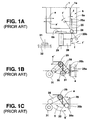
- a cassette discharge lever 25 is secured through a vertical supporting pin 26 to a bottom plate 6a of a cassette stage 6 so as to be freely rotatable in directions as indicated by arrows f,f' within a horizontal plane
- a cam driven lever 28 for rotationally driving the cassette discharge lever 25 is secured through a horizontal supporting pin 29 to a side plate 6b of a cassette stage 6 so as to be freely rotatable in directions as indicated by arrows g,g' within a vertical plane.
- the cam driven lever 28 is rotationally urged in the direction of the arrow g' by a torsion coil spring 30 to bring the lower end 28a of the cam driven lever 28 into contact with the other end 25b of the cassette discharge lever 25 from the direction of the arrow g' at all times. Further, a cam 31 which is located so as to be overlapped with a horizontal movement locus of the lower end 28a of the cam driven lever 28 is secured to a chassis side plate 32.
- a tape cassette 1 is inserted into the cassette stage 6 from a cassette insertion port of a front panel (not shown) in a direction of an arrow a
- one end 25a of the cassette discharge lever 25 is pushed in the direction of the arrow a by a front end 1a of the tape cassette 1
- the cam driven lever 28 is pushed against the torsion coil spring 30 in the direction of the arrow g by the other end 25b of the cassette discharge lever 25.
- the other end 25b of the cassette discharge lever 25 is pushed in the direction of an arrow f' by the cam driven lever 28, and the tape cassette 1 in the cassette stage 6 is pushed in the direction of the arrow a' by one end 25a of the cassette discharge lever 25, whereby the tape cassette 1 is violently pushed out of the cassette insertion port in the direction of the arrow a' so that the tape cassette 1 can be easily pulled out at the outside of the front panel.
- the lower end 28a of the cam driven lever 28 is brought into contact with the other end 25b of the cassette discharge lever 25 from the direction of the arrow g' by the torsion coil spring 30, whereby the lower end 28a of the can driven lever 28 is kept to be overlapped with the cam 31.
- the cam driven lever 28 in the course of a loading operation of the tape cassette 1 from the cassette insertion position to the cassette mount position in the direction of the arrow a by the cassette stage 6, as shown in of Fig. 1C, the cam driven lever 28 is once rotated in the direction of the arrow g against the torsion coil spring 30 by the cam 31, and then the cam driven lever 28 is violently rotated in the direction of the arrow g' by the torsion coil spring 30 at the instantaneous time when the cam driven lever 28 gets over the cam 31 in the direction of the arrow a, so that the cam driven lever 28 violently collides against the other end 25b of the cassette discharge lever 25 from the direction of the arrow g' and it causes an uncomfortable collision noise "click sound" at all times.
- a clamp force in the cassette stage 6 is required to be increased. If the clamp force to the tape cassette 1 in the cassette stage 6 is increased, a strong force is needed when the tape cassette 1 is manually inserted into the cassette stage 6, and also a strong force is needed when the tape cassette 1 is discharged by the cassette discharge lever 25 for ejection. Therefore, there occurs various problems, for example, the rigidity of the cassette discharge lever 25 and the cam driven lever 28 must be increased.
- the present invention has been implemented to solve the above problems, and it has an object to provide a cassette type recording/reproducing apparatus which can beforehand prevent a cam driven lever from violently colliding against a cassette discharge lever in the course of a loading operation of a tape cassette.
- Fig. 1D There has been also known another conventional technique as shown in Fig. 1D, which is relating to a cassette type recording/reproducing apparatus such as a video recorder or the like.
- an openining/closing lid 5 for opening/closing a cassette insertion port 4 of a front panel 3 from the inside is secured to a cassette stage 6 through a supporting pin 7 so as to be freely rotatable in the directions indicated by arrows c,c', and a cassette press member is constructed by the opening/closing lid 5.
- the cassette stage 6 is horizontally retracted from the cassette insertion position P 1 into the cassette retract position P 2 in the direction of the arrow a by a cassette loading mechanism (not shown), and then the cassette stage 6 is vertically descended to the cassette mount position P 3 in the direction of the arrow b.
- the tape cassette 2 is horizontally loaded to the cassette mount position P 3
- the tape cassette 2 is mounted horizontally onto plural cassette position pins 8, and the tape cassette 2 is upwardly pushed to the position of a height H 1 from the bottom plate 6a of the cassette stage 6.
- the tape cassette 2 is pressed and fixed onto the plural cassette positioning pins 8 by the cassette press force in the direction of the arrow d' of the opening/closing lid 5, and the front lid 2A of the tape cassette is opened upwardly.
- a magnetic tape in the tape cassette 2 is pulled out from the cassette by the tape loading mechanism and loaded onto a rotating head drum (not shown) to perform information recording/reproducing operation.
- the cassette stage 6 is returned in the directions of arrows b',a' from the cassette mount position P 3 via the cassette retract position P 2 to the cassette insertion position P 1 by a reversing operation to the cassette loading operation, and finally the tape cassette 2 is discharged to the outside of the cassette insertion port 4.
- the cassette insertion port 4 of the front panel 3 is opened/closed from the inside by the opening/closing lid 5 which is freely rotatably secured to the cassette stage 6, and reciprocatively moved between the cassette insertion position P 1 end the cassette mount position P 3 together with the cassette stage 6, and the opening/closing lid is also used as a cassette press member for pressing onto the bottom plate 6a of the cassette stage 6 the tape cassette 2 which is inserted from the cassette insertion port 4 into the cassette stage 6. Therefore, the number of parts and the number of fabrication steps can be reduced to promote reduction of the cost.
- a proper portion of the tape cassette 2 which is located at a rear side a movable space of the front lid 2A of the tape cassette 2 can be pressed by the opening/closing lid 5, so that the cassette type recording/reproducing apparatus of this prior art has high resistance to external disturbance or the like.
- the present invention has been further implemented to solve the above problem, and has another object to provide a cassette type recording/reproducing apparatus in which the cassette insertion port of the front panel is opened/closed from the inside by an opening/closing lid which is freely rotatably secured to a cassette stage and moved together with a cassette stage, and which can prevent a cassette double insertion, etc. in a cassette loading operation in advance.
- Fig. 1E which is relating to the cassette type recording/reproducing apparatus such as a video recorder or the like.
- the tape cassette 2 is inserted from the cassette insertion port 4 of the front panel 3 into the cassette stage 6 serving as the cassette feeding means in the direction of the arrow a, the tape cassette 2 is pressed and fixed onto the bottom plate 6a of the cassette stage 6 by the cassette press member 5 which is secured to the cassette stage 6.
- the cassette stage 6 is horizontally pulled from the cassette insertion position P 1 to the cassette retract position P 2 in the direction of the arrow a by the cassette loading mechanism (not shown), and then vertically descended to the cassette mount position P 3 in the direction of the arrow b to horizontally load the tape cassette 2 to the cassette mount position P 3 .
- the tape cassette 2 is horizontally mounted on the plural cassette positioning pins 8, and pushed upwardly to the height H 1 from the bottom plate 6a of the cassette stage 6.
- the tape cassette 2 is pressed and fixed onto the plural cassette positioning pins 8 by the cassette press member, and the front lid 2A of the tape cassette 2 is upwardly opened.
- the magnetic tape in the tape cassette 2 is pulled out from the cassette by the tape loading mechanism and loaded onto the rotating head drum (not shown) to perform the information recording/reproducing operation.
- the cassette stage 6 is returned from the cassette mount position P 3 through the cassette retract position P 2 to the cassette insertion position P 1 in the directions of the arrows b', a' by the counter operation to the cassette loading operation, and the tape cassette 2 is discharged to the outside of the cassette insertion port 4.
- the cassette press member 5 In the above-described cassette type recording/reproducing apparatus, the cassette press member 5 must be disposed to be displaced nearer to the cassette discharge direction side (in the direction of the arrow a') than the opening/closing space S 1 of the front lid 2A in order to prevent the interference between the cassette press member 5 and the front lid 2A of the tape cassette 2.
- the cassette press member 5 can never press the upper portion of the front lid 2A portion which is the tip of the tape cassette 2, so that no countermeasure cannot be taken to the insertion of the tape cassette at an upwardly slant angle ( ⁇ 1 ) as indicated by a solid line of Fig. 1E to the horizontal reference indicated by a one-dotted chain line of Fig. 1E when the tape cassette 2 is inserted from the cassette insertion port 4 into the cassette stage 6 in the direction of the arrow a.
- a space S 2 as indicated by a one-dotted chain line of Fig. 1E corresponds to a horizontal moving space of the cassette press member 5, and thus a fixed stopper for preventing the slant insertion of the tape cassette 2 cannot be disposed in the space S 2 .
- Further object of the present invention is to provide a cassette two recording/reproducing apparatus which can prevent a tape cassette from being obliquely inserted into a cassette stage in advance.
- Fig. 1F There has been further known a conventional technique show in Fig. 1F, which is relating to a cassette type recording/reproducing apparatus such as a video tape recorder or the like.
- a cassette type recording/reproducing apparatus such as a video tape recorder or the like.
- two types of tape cassettes 1 and 2 which are different in size D 1 , D 2 ) can be properly used.
- a cassette identifying member 9 for identifying the type (size) of the tape cassettes 1,2, a cassette insertion guide 10 which is switched in accordance with the indentification result of the cassette identifying member 9, and a lock lever (not shown) for locking the cassette identifying member 9 and the cassette insertion guide 10 at a position which is downwardly escaped (shifted) from the cassette insertion space, are disposed inside the cassette insertion port 4 which is a laterally elongated opening formed in the front panel 3.
- the cassette stage 6 serving as the cassette feeding means is disposed at the rear side of the cassette insertion guide 10, and there is disposed a cassette loading mechanism for reciprocatively moving the cassette stage 6 in the directions of the arrows a,b and a',b' along a substantially L-shaped moving locus among the cassette insertion position P 1 , the cassette retracting position P 2 at the rear side of the cassette insertion position and the cassette mount position P 3 at the lower side of the cassette retracting position.
- the tape cassette 1,2 is selectively inserted from the direction of the arrow a into the cassette stage 6.
- the type (size) of the tape cassette 1,2 is identified by the cassette identifying block 9 to switch the cassette insertion guide block 10.
- the large-size tape cassette 2 is identified by the cassette identifying member 9, and the cassette insertion guide 10 is downwardly escaped from the cassette insertion space together with the cassette identifying member 9.
- the cassette identifying member 9 is locked at the lower side of the cassette insertion space by the lock lever (not shown).
- the small-size tape cassette 1 is guided onto the stage center at the center position in the right and left directions in the cassette stage 6 by the cassette insertion guide block 10, so that the small-size tape cassette 1 can be prevented from being erroneously inserted at a displaced position to the right or left side in the cassette stage 6 by the cassette insertion guide block 10.
- the cassette loading mechanism is actuated to horizontally retract the cassette stage 6 from the cassette insertion position P 1 to the cassette retract position P 2 in the direction of the arrow a, and then the cassette stage is vertically descended in the direction of the arrow b from the cassette retract position P 3 to the cassette mount position P 3 , whereby the tape cassette 1,2 is horizontally loaded onto the plural cassette positioning pins while upwardly floated at the height H 1 from the bottom plate 6a of the cassette stage 6.
- the front lid 1A, 2A secured to the front end of the tape cassette 1,2 is upwardly opened in the direction of the arrow b'.
- the magnetic tape in the tape cassette 1,2 is pulled out from the cassette by the tape loading mechanism, and loaded onto the rotating head drum (not shown) to perform information recording/reproducing operation.
- the cassette stage 6 is vertically lifted up in tine direction of the arrow b' from the cassette mount position P 3 to the cassette retract position P 2 by the counter operation to the cassette loading operation, and then horizontally moved in the direction of the arrow a' to the cassette insertion position P 1 so that the tape cassette 1,2 is discharged to the outside of the front panel 3 from the cassette insertion port 4 by cassette discharge means (not shown).
- the lock of the lock lever is released by the cassette stage 6, and the cassette identifying member 9 and the cassette insertion guide 10 are escaped together into the cassette insertion space again.
- the cassette identifying member 9, the cassette insertion guide 10 and the lock lever for locking these members at the lower side of the cassette insertion space are provided such places that an operator can easily see these members in the cassette insertion port 4. Therefore, the outward appearance of the cassette type recording/reproducing apparatus is remarkably bad.
- the operator can easily touch the cassette identifying member 9, the cassette insertion guide 10 and the lock lever from the outside of the cassette insertion port 4. Therefore, if the operator carelessly touches the lock lever under the cassette loading state to release the lock, the cassette identifying member 9 and the cassette insertion guide carelessly spring into the cassette insertion space. Therefore, at the subsequent cassette eject time, the tape cassette 1,2 collides against the cassette identifying member 9 and the cassette insertion guide 10, resulting in such a critical accident that that these members are damaged.
- the present invention has been also implemented to overcome the above problem, and has further object to provide a cassette type recording/reproducing apparatus in which a cassette insertion guide and a cassette identifying member re allowed to be safely accommodated at the outside of a cassette insertion space under a cassette loading state.
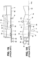
- cassette type recording/reproducing apparatus such as a video tape recorder as shown in Figs. 1G and 1H.
- This conventional cassette type recording/reproducing apparatus is suitably applicable to two types of tape cassettes 1 and 2 which are different in size (D 1 , D 2 ).
- each of these types of tape cassettes 1 and 2 is selectively inserted from the direction of the arrow a from the cassette insertion port of the front panel into the cassette stage serving as the cassette feeding means (not shown), and then the cassette state is moved from the cassette insertion position to the cassette mount position to selectively load each of the two types of tape cassettes 1 and 2 to the cassette mount position.
- the tape cassette 1,2 is inserted from the cassette insertion port into the cassette stage from the direction of the arrow a, the tape cassette 1,2 is guided by a cassette guide (not shown), and positioned at an insertion reference position P 12 on the stage center P 11 which is the center position of the cassette stage in the right and left directions.
- the tape cassette 1,2 When the tape cassette 1, 2 is selectively loaded to the cassette mount position by the cassette stage, the tape cassette 1,2 is inserted from the upper side through a pair of positioning reference holes 14 common to the tape cassettes 1 and 2 into a pair of cassette positioning pins 8 which are common to the tape cassettes 1 and 2 and located at the cassette mount position, where the tape cassettes 1 and 2 are can be accurately positioned at the insertion reference position P 12 on the state center P 11 at the cassette mount position.
- two members being detected (hereinafter referred to as "detection targets") 15 and 16 which are located at different positions with respect to the common positioning reference holes 14 to the tape cassettes 1 and 2 are formed at the front ends 1a and 2a of the tape cassettes 1 and 2, and two detection members 18 and 19 are provided to a detection lever 17 which is secured to the cassette stage so as to be freely rotatable in the directions of the arrows e.e'.
- two light reflection type optical sensors 22 and 23 are selectively switched on/off by two light reflection plates 20 and 21 which are provided to the detection lever 17 when these detection members 18 and 19 selectively detect the two detection targets 15 and 16, whereby the insertion position detection and the type detection of two types of tape cassettes 1 and 2 can be simultaneously performed.
- the detection member 18 for detecting a small-size tape cassette 1 is spaced from the front end 2a of the large-size tape cassette 2, and thus a gap 24 can be formed between the detection member 18 and the front end 2a of the large-size tape cassette 2. Accordingly, in the loading and eject operations of the large-size tape cassette 2 to and from the cassette mount position, the front lid of the large-size tape cassette 2 can be smoothly opened/closed without interfering with the detection member 18.
- the detection member of the detection lever for detecting the small-size tape cassette still suffers interference by the front end 2a of the large-size tape cassette 2, so that it obstructs the opening/closing operation of the front lid of the large-size tape cassette.
- an optical sensor 22 for detecting a small-size tape cassette is preferentially turned on in synchronism with the rotation of the detection lever 17 in the direction of the arrow e, and then an optical sensor for detecting the large-size tape cassette is turned on. Therefore, it is required that the small-size tape cassette detecting optical sensor 22 which is once turned on is switched from the On-state to the Off-state.
- the moving range of the detection lever 17 is limited, so that it is very difficult to adjust the switching operation of the small-size tape cassette detecting sensor 22 in the order of OFF-ON-OFF, and this adjustment work causes a remarkable increase in cost.
- the present invention has been also implemented to solve the above problem, and has further object to provide a cassette type recording/reproducing apparatus in which both the insertion position detection and the cassette type detection of plural types of tape cassettes which are different in size can be accurately performed with a simple structure.
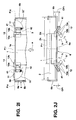
- the large-size tape cassette 2 it is positioned on the stage center P 11 by both right and left side plates 6b of the cassette stage 6, and it is positioned at the insertion reference position P 12 by a pair of right and left cassette stoppers 11 which are formed at the front end of the bottom plate 6a.
- the small-size tape cassette 1 it is positioned on the stage center P 11 by a pair of right and left cassette guides 12a of a pair of right and left stopper blocks 12 which are secured to the bottom plate 6a of the cassette stage 6, and it is positioned at the insertion reference position P 12 by a pair of right and left cassette stoppers 12b.
- the pair of right and left stopper blocks 12 are secured to the lower surface side of the bottom plate 6a of the cassette stage 6 by a pair of right and left leaf springs 13, and when the large-size tape cassette 2 is inserted into the cassette stage 6, the pair of right and left stopper blocks 12 are escaped to the lower side of the bottom plate 6a against the pair of right and left leaf springs 13.
- the tape cassette 1,2 which is selectively inserted into the cassette stage 6 as described above is cramped on the bottom plate 6a of the cassette stage 6 by the cassette press member.
- the cassette stage 6 is horizontally retracted from the cassette insertion position to the cassette retract position in the direction of the arrow a by the cassette loading mechanism (not shown), and then it is vertically descended to the cassette mount position, whereby the tape cassette 1,2 is loaded so as to be horizontally mounted on the plural cassette positioning pins (not shown) provided at the cassette mount position by the cassette pressing force of the cassette press member.
- the magnetic tape of the tape cassette 1,2 is pulled out from the cassette by the tape loading mechanism, and loaded onto the rotating head drum (not shown) to perform information recording/reproducing operation.
- the cassette stage 6 is returned from the cassette mount position via the cassette retract position to the cassette insertion position, and finally the tape cassette 1,2 is discharged to the outside of the cassette insertion port.
- the pair of right and left stopper blocks 12 for positioning the small-size tape cassette 1 at the insertion reference position P 12 on the stage center P 11 are secured to the bottom plate 6a of the cassette stage 6 by the pair of right and left leaf springs 13. Therefore , if the rigidity of the leaf springs 13 is low, the leaf springs 13 would be irregularly deformed due to distortion or the like if the small-size tape cassette 1 is carelessly strongly inserted into the cassette stage 6, and the pair of right and left cassette guides 12a or the cassette stoppers 12b are deviated from the normal position, so that the small-size tape cassette 1 cannot be accurately positioned to the insertion reference position P 12 on the stage center P 11 . If the position of the tape cassette 1,2 in the cassette stage is inaccurate, there would occur such a cassette loading miss that the tape cassette 1,2 cannot be accurately mounted on the plural cassette position positioning pins when the tape cassette 1,2 is loaded to the cassette mount position.
- the thickness or width of the pair of right and left leaf springs 13 is set to a large value to increase the rigidity thereof to an excessive value, a cassette push-up force of the stopper blocks 12 which corresponds to the reaction force of the leaf springs 13 is excessively large, and thus a strong force is needed to insert the large-size tape cassette 2 into the cassette stage 6, so that it is remarkably difficult to insert the large-size tape cassette 2. Accordingly, the insertion degree of the large-size tape cassette 2 is insufficient, and the large-size tape cassette 2 is loaded while it is not accurately inserted to the insertion reference position P 12 , resulting in the cassette loading miss in which the large-size tape cassette 2 cannot accurately mounted on the plural cassette positioning pins of the cassette mount position.
- the present invention has been also implemented to overcome the above problem, and has further object to provide a cassette type recording/reproducing apparatus in which any tape cassette can be easily inserted when plural types of tape cassettes which are different in size are selectively inserted into the cassette stage, and any tape cassette can be accurately positioned in the cassette stage.
- a first object of the present invention is to provide a cassette type recording/reproducing apparatus which can beforehand prevent a cam driven lever from violently colliding against a cassette discharge lever in the course of a loading operation of a tape cassette.
- a second object of the present invention is to provide a cassette type recording/reproducing apparatus in which the cassette insertion port of the front panel is opened/closed from the inside by an opening/closing lid which is freely rotatably secured to a cassette stage and moved together with a cassette stage, and which can prevent a cassette double insertion, etc. in a cassette loading operation in advance.
- a third object of present invention is to provide a cassette type recording/reproducing apparatus which can prevent a tape cassette from being obliquely inserted into a cassette stage in advance.
- a fourth object of the present invention is to provide a cassette type recording/reproducing apparatus in which a cassette insertion guide and a cassette identifying member re allowed to be safely accommodated at the outside of a cassette insertion space under a cassette loading state.
- a fifth object of the present invention is to provide a cassette type recording/reproducing apparatus in which both the insertion position detection and the cassette type detection of plural types of tape cassettes which are different in size can be accurately performed with a simple structure.
- a sixth object of the present invention is to provide a cassette type recording/reproducing apparatus in which any tape cassette can be easily inserted when plural types of tape cassettes which are different in size are selectively inserted into the cassette stage, and any tape cassette can be accurately positioned in the cassette stage.
- a cassette type recording/reproducing apparatus includes a cassette insertion port formed on a front panel, a cassette stage which is reciprocatively moved between a cassette insertion position at which a tape cassette is inserted from the cassette insertion port, and a cassette mount position at which the inserted tape cassette is subjected to recording/reproducing operation, a cassette discharge lever which is freely rotationally secured to the cassette stage, and pushed and moved by the cassette which is inserted through the cassette insertion port into the cassette stage, a cam driven lever which is freely rotationally secured to the cassette stage, and serves to rotationally drive said cassette discharge lever in a cassette discharging direction, a cam which is disposed at a fixed position on a movement locus of the cam driven which is moved together with the cassette stage, and kicks the cam driven lever during the cassette stage being moved from the cassette mount position to the cassette insertion position, whereby the cassette discharge lever is rotationally driven in the cassette discharge direction by the cam driven lever,
- a cassette type recording/reproducing apparatus includes a cassette insertion port formed on a front panel, a cassette stage which is reciprocatively moved between a cassette insertion position at which a tape cassette is inserted from the cassette insertion port, and a cassette mount position at which the inserted tape cassette is subjected to recording/reproducing operation, an opening/closing lid which is freely rotatably secured to the cassette stage so as to be movable together with the cassette stage, closes the cassette insertion port from the inside thereof through the movement of the cassette stage to a cassette insertion position, and is pushed and opened by a tape cassette which is inserted from the cassette insertion port into the cassette stage, and a double insertion preventing lid which is evacuated to a lid closing position where the cassette insertion port is opened when the cassette stage is moved to the cassette insertion position, and moved to a lid closing position where the cassette insertion port is closed from the inside thereof when the cassette stage is moved to the
- a cassette type recording/reproducing apparatus includes a cassette insertion port formed on a front panel, a cassette stage which is reciprocatively moved between a cassette insertion position at which a tape cassette is inserted from the cassette insertion port, and a cassette mount position at which the inserted tape cassette is subjected to recording/reproducing operation, a cassette press member which is secured to the cassette stage and adapted to press a tape cassette from the upper side thereof at a position which is nearer to a cassette discharge direction side than the front lid of the tape cassette, the tape cassette being inserted from the cassette insertion port into the cassette stage, a cassette slant insertion preventing stopper which is secured to the cassette stage and adapted to relatively press a front lid portion of a tape cassette from the upper side thereof, the tape cassette being inserted from the cassette insertion port into the cassette stage, whereby the tape cassette is prevented from being obliquely inserted in a forward and upward direction into the cassette stage
- a cassette type recording/reproducing apparatus includes plural types of tape cassettes which are different in size from one another, a cassette insertion port formed in a front panel, a cassette stage which is reciprocatively moved between a cassette insertion position at which the plural types of tape cassettes are selectively inserted from the cassette insertion port, and a cassette mount position at which the inserted plural tape cassettes are subjected to recording/reproducing operation, a cassette insertion guide which is disposed inside the cassette insertion port, and adapted to regulate the insertion position of a small-size tape cassette into the cassette stage, a cassette identifying member which is disposed inside the cassette insertion port, and is driven by a large-size tape cassette to allow the cassette insertion guide to escape out of a cassette insertion space, and control means for moving the cassette insertion guide and the cassette identifying member to an operation position in the cassette insertion space when the cassette stage is moved to the cassette insertion position, and accommodating the cassette insertion
- a cassette type recording/reproducing apparatus includes plural types of tape cassettes which are different in size from one another, a cassette insertion port formed in a front panel, a cassette stage which is reciprocatively moved between a cassette insertion position at which the plural types of tape cassettes are selectively inserted from the cassette insertion port, and a cassette mount position at which the inserted plural tape cassettes are subjected to recording/reproducing operation, detection means for simultaneously detecting the insertion position and the type of the plural types of tape cassettes which are selectively inserted from the cassette insertion port into the cassette stage, first and second detection targets which are formed at different positions with respect to positioning reference holes which are common to the plural types of tape cassettes, the first and second detection targets constituting the detection means, a double lever mechanism having first and second detection levers which are freely rotatably secured to the cassette stage, and are rotationally driven by the first and second detection targets, the double lever mechanism constituting the detection means, and first and
- a cassette type recording/reproducing apparatus includes plural types of tape cassettes which are different in size from one another, a cassette insertion port formed in a front panel, a cassette stage which is reciprocatively moved between a cassette insertion position at which the plural types of tape cassettes are selectively inserted from the cassette insertion port, and a cassette mount position at which the inserted plural tape cassettes are subjected to recording/reproducing operation, a pair of right and left stopper blocks each having a cassette guide and a cassette stopper for positioning to an insertion reference position on a stage center a small-size tape cassette of the plural types of tape cassettes which are selectively inserted from the cassette insertion port into the cassette stage, a pair of right and left supporting pins through which the pair of right and left stopper blocks are freely rotatably secured to the cassette stage so that the stopper blocks can freely get into and out of the cassette stage, and a pair of right and left rotational urging means for
- Figs. 2 to 47J Preferred embodiments in which the present invention is applied to a cassette type recording/reproducing apparatus such as a video cassette recorder or the like will be described with reference to Figs. 2 to 47J.
- the same structural portions as Figs. 1A to 1J are represented by the same reference numerals, and the duplicative description thereof is omitted.
- a tape cassette 1 is inserted in a direction of an arrow a into a cassette stage 6 through a cassette insertion port of a front panel as described later, and the tape cassette 1 is reciprocatively moved between a cassette insertion position and a cassette mount position as described later.
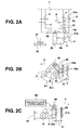
- a cassette discharge lever 51 which is pushed by the tape cassette 1 which is inserted through the cassette insertion port into the cassette stage 6 in the direction of the arrow a, is secured to a bottom plate 6a of the cassette stage 6 through a support pin 142 so as to be freely rotatable in the directions of arrows e, e' within a horizontal plane.
- a cam driven lever 28 which serves to rotationally drive the cassette discharge lever 51 in the direction of the arrow e' which corresponds to a cassette discharge direction is secured to a side plate 6b of the cassette stage 6 through a support pin 29 so as to be freely rotatable in the directions of arrows g,g' within a vertical plane.
- a cam 31 which is disposed at a fixed position which is overlapped with a movement locus of the cam driven lever 28 which is moved together with the cassette stage 6, is secured to a chassis side plate 32.
- control means 50 for positionally regulating the cam driven lever 28 within a fixed range ⁇ 12 at the middle position of a swing range ⁇ 11 in which the cam driven lever 28 is rotated by the cam 31.
- Fig. 2A when the tape cassette 1 is inserted in the direction of the arrow a into the cassette stage 6 through the cassette insertion port in a cassette loading operation, one end 51a of the cassette discharge lever 51 is pushed by the direction of the arrow e by the tape cassette 1, and the cassette discharge lever 51 is rotated in the direction of the arrow e.
- the tape cassette 1 is loaded from the cassette insertion position to the cassette mount position in the direction of the arrow a by the cassette stage 6, and in the course of the cassette loading operation, the lower end 28a of the cam driven lever 28 is once rotated in the direction of an arrow g by the cam 31 as shown in Fig. 2C.
- the cam driven lever 28 gets over the cam 31 in the direction of the arrow a, the cam driven lever 28 is rotated and returned in the direction of the arrow g' by the control means 50. At this time, the lower end 28a of the cam driven lever 28 is stopped at such as a position as to keep a gap interval 27 from the other end 51b of the cassette discharge lever 51, whereby the lower end 28a of the cam driven lever 28 is prevented from coming into forcible contact with the other end 51b of the cassette discharge lever 51 from the direction of the arrow g'.
- the cam driven lever 28 In the eject operation of the tape cassette 1 from the cassette mount position to the cassette insertion position in the direction of the arrow a' by the cassette stage 6, the cam driven lever 28 is relatively kicked from the direction of the arrow a by the cam 31 as shown in Fig. 2B, whereby the cam driven lever 28 is rotationally driven in the direction of the arrow g'. As shown in Fig.
- the other end 51b of the cassette discharge lever 51 is pushed in the direction of the arrow f' by the cam driven lever 28, and the tape cassette 1 in the cassette stage 6 is pushed in the direction of the arrow a' by the one end 51a of the cassette discharge lever 51 to violently push the tape cassette 1 to the outside of the cassette insertion port in the direction of the arrow a', thereby facilitating a pull-out operation of the tape cassette at the outside of the front panel.
- the clamp force to the tape cassette 1 in the cassette stage 6 can be sufficiently weakened.
- the tape cassette 1 can be easily inserted into the cassette stage 6 with a weak force in a cassette insertion operation, also the tape cassette 1 can be easily discharged with a weak force when the tape cassette 1 is discharged in the direction of the arrow a' by the cassette discharge lever 51 in the eject operation, and the rigidity of the cassette discharge lever 51 and the cam driven lever 28 can be sufficiently reduced.
- a magnetic tape 62 which are wound around a pair of right and left tape reels 61 having different diameters is accommodated in each of small-size and large-size tape cassettes 1, 2 which are different in size (the depth in the forward and rearward direction and the width in the right and left direction) D 1 and D 2 and in thickness T 1 , T 2 .
- Each of these magnetic tapes 62 is passed along the inner side of the front lid 1A,2A having an inner-and-outer dual structure which is secured to the front end 1a, 2a of the small-size and large-size tape cassettes 1, 2.
- a cut-out 64 having substantially the same shape is formed at the center portion of the front end 1a, 2a side of the bottom plate 1c, 2c in which a pair of right and left reel table insertion holes 63 of the small-size and large-size tape cassettes 1, 2 are formed.
- a pair of right and left positioning reference holes 14 are formed at both the right and left side positions of the cut-out 64 of the bottom plate 1c, 2 of the small-size and large-size tape cassettes 1, 2, and it is commonly used for the small-size and large-size tape cassettes 1,2. That is, the pair of right and left positioning reference holes 14 are allocated at the right and left sides at the same distance L 1 from the cassette center P 5 and they are formed at the rearward position from the front end 1a, 2a at the some dimension L 2 .
- a pair of right and left slits 65 along both side surfaces 1b,2b of the small-size and large-size tape cassettes 1,2 which extend from the front lid 1A,2A to the bottom plate 1c, 2c are formed in parallel to the cassette center P 5 at both the right and left end sides of the small-size and large-size tape cassettes 1, 2.
- a lock lever 66 of the front lid 1A,2A is disposed at the rear side from the slits 65. In the small-size tape cassette 1, the lock lever 66 is disposed in only one slit 65.
- a pair of right and left detection-target portions 15, 16 which are used to simultaneously perform the detection of an insertion position in the cassette stage 6 and the detection of a type (size) as described above are formed on the front end surface of the bottom plate 1c,2c which is the front end 1a, 2a of the small-size and large-size tape cassettes 1, 2.
- the detection-target portions 15, 16 at the right side of Figs. 3 and 4 are formed at the common position to the reference hole 14, and the detection-target portions 15, 16 at the left side are formed at different positions with respect to the reference hole 14.
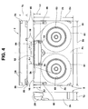
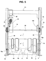
- the cassette stage 6 is formed of a metal plate or the like, and it is constructed to have an upwardly opened and substantially U-shaped section by a horizontal bottom plate 6a, and a pair of right and left side plates 6b erecting vertically and upwardly from both the right and left ends of the bottom plate 6a.
- a pair of right and left cassette stoppers 11 for the large-size tape cassette 2 are integrally formed at both the right and left sides of the rear end of the bottom plate 6a (the end portion in the arrow a direction).
- a pair of stopper blocks 12 for guiding the small-size tape cassette 1 onto the stage center P 11 and position it to the insertion reference position P 12 .
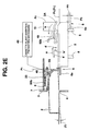
- a cassette loading mechanisms 71 is disposed inside of the cassette insertion port 4 of the front panel 3, and the chassis of the cassette loading mechanism 71 comprises a borizontal chassis top plate 33 which is integrally formed with and bridged over the upper portions of a pair of right and left vertical chassis side plates formed of metal plates or the like, and it is designed to be downwardly opened and substantially U-shaped in section.
- a front base 34 serving as a fixing member which is formed of synthetic resin and designed to be upwardly opened and substantially U-shaped is horizontally suspended between the front ends (the end portions in the direction of the arrow a') of the pair of right and left chassis side plates 32 along the lower end and both the side edges of the cassette insertion port 4.
- the cassette stage 6 is disposed horizontally at the rear position of the cassette insertion port 4 between the pair of right and left chassis side plates 32.
- Respective pairs of right and left L-type guide grooves 72 each comprising a horizontal passage 72a and a vertical passage 72b which is hung down from the rear end of the horizontal passage 72a, totally four L-type guide grooves 72 are formed in the pair of right and left chassis side plates 32.
- Rack guide plates 73 are secured in parallel on both the side surfaces of the end portions of the rear end sides (the end portions in the direction of the arrow a) of the pair of right and left chassis side plates 32, and horizontal guide grooves 74 are formed along the upper end edge sides on the inner side surfaces of the rack guide plates 73.
- a pair of right and left rack plates 75 are disposed in parallel at the inside positions of the pair of right and left rack guide plates 74 on both side surfaces of the pair of right and left chassis side plates 32.
- Respective pairs of front and rear guide rollers 76 at each of the front and rear sides which are fixed at the inside and outside of the positions near to both the front and rear ends (both ends in the directions of the arrow a,a') of the rack plates 75, are movably inserted in one horizontal passage 72a of the L-type guide grooves 72 and the horizontal guide groove 74, and thus these rack plates 75 are horizontally slidable along the pair of right and left chassis side plates 32 in the directions of the arrow a,a' which are the forward and rearward directions.
- a pair of slant guide grooves 77 which are provided at each of front and rear sides and designed to be slant at a predetermined angle to the horizontal reference are formed at the front end sides (in the direction of the arrow a') of the pair of right and left rack plates 75, and these slant guide grooves 77 are disposed to cross each pair of L-type guide grooves 72. Further respective pairs of guide rollers 76 at the right and left sides, totally four guide rollers 72 are movably inserted in each L-type guide groove 72 and each slant guide groove 77 at the crossing point of these grooves.
- a loading motor 80 is fixed through a motor holder 79 to the inside of the rear end side of one chassis side plate 32, and a driving shaft 82 which is forwardly and backwardly rotated through a gear train 81 by the loading motor 80 is horizontally suspended between the upper portions of the pair of right and left chassis side plates 32.
- a pair of right and left pinions 83 which are fixed to both the right and left ends of the driving shaft 82 are engaged with a pair of right and left racks 75a which are horizontally formed along the upper end edges of the pair of right and left rack plates 75.
- the cassette loading mechanism 71 rotates the pair of right and left pinions 83 forwardly and backwardly through the gear train 81 and the driving shaft 82 with the loading motor 80 to drive the racks 75a of the pair of right and left rack plates 75 in the directions of the arrows a,a' by the pinions 83 in synchronism with each other, the pair of right and left rackplates 75 are guided along the one horizontal passage 72a of the L-type guide grooves 72 and the horizontal guide groove 74 and horizontally and synchronously moved in the directions of the arrows a',a along the pair of right and left chassis side plates 32.
- each pair of right and left guide rollers 78 of the cassette stage 6 are synchronously moved in an L-shaped locus in the directions of the arrows a,b and the arrow a', b' along the horizontal passages 72a and the vertical passages 72b of the respective pairs of L-type guide grooves 72 of the pair of right and left chassis side plates 32 of each right and left guide rollers 78 of the cassette stage 6 by each pair of right and left rack plates 75.
- the cassette stage 6 is reciprocatively moved along the L-shaped locus in the directions of the arrows a,b and the directions of the arrows a', b' among a cassette insertion position P 1 indicated by a dotted line, a cassette retract position P 2 as indicated by a one-dotted chain line to which the cassette is horizontally retracted, and a cassette mount position P 3 as indicated by a two-dotted chain line to which the cassette is vertically and downwardly moved.
- a cassette press mechanism 91 is mounted at the upper side of the cassette stage 6.
- the cassette press mechanism 91 has a opening/closing lid 5 for opening/closing the cassette insertion port 4 of the front panel 3 from the inside, and a cassette press lever 92 which is upwardly and downwardly rotated while supporting the opening/closing lid 5.
- the cassette press lever 92 is designed to be downwardly opened and substantially U-shaped in section by a pair of right and left side plates 92a and a top plate portion 92b through which the upper end portions of the side plates 92a are horizontally linked, and the top plate portion 92b is formed on a mount stand of a cassette slant insertion preventing stopper as described later.
- the cassette press lever 92 is secured to the rear ends of the pair of right and left side plates 6b of the cassette stage 6 through a pair of right and left horizontal support pins 93 by the rear ends of the pair of right and left side plates 92a so as to be freely rotatable in the directions of the arrows d,d' which are the upward and downward directions.
- the cassette press lever 92 is rotationally urged in the direction of the arrow d' corresponding to a cassette press direction by a pair of right and left press springs 94 serving as rotational urging means comprising an extension spring to come into contact with and stop at the pair of right and left stoppers 95 which are integrally formed on the right and left side plates 6b of the cassette stage 6.
- the opening/closing lid 5 is formed of synthetic resin or the like, and both the right and left sides of the upper end of the opening/closing lid 5 are secured to the insides of the front ends of the pair of right and left side plates 92a of the cassette press lever 92 through a pair of right and left horizontal support pins 7 so as to be freely rotatable in the directions of arrows c,c' which correspond to the forward and rearward direction and the upward and downward direction.
- the opening/closing lid 5 is rotationally urged in the direction of the arrow c' by a pair of right and left opening/closing lid springs 96 serving as rotational urging means for closing the lid which comprise torsion coil springs, whereby the opening/closing lid 5 abuts against stoppers integrally formed at the insides of the front end of the pair of right and left arm portions 92a, and stops at the lid closing position of the cassette insertion port 4 shown in Fig. 9.
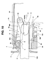
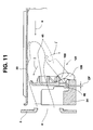
- a cassette double insertion preventing lid 45 of a cassette double insertion preventing mechanism 101 is fixed to the rear end (the end portion in the direction of the arrow a) of the front base 34 through a pair of right and left horizontal support pins 46 so as to be freely rotatable in the directions of arrows j,j' which correspond to the upward and downward directions.
- a pair of right and left opening/closing mechanisms 47 for opening/closing the cassette double insertion preventing lid 45 in the directions of the arrows j,j' are secured to both side surfaces of the pair of right and left chassis side plates 32,
- Each of these opening/closing mechanisms 47 comprises a seesaw type driving lever 103 which is mounted to the chassis side plate 32 through a horizontal support pin 102 so as to be rotationally driven in the directions of arrows m,m' corresponding to the upward and downward directions, a cam driven roller 104 which is fixed to the rear end of the driving lever 103, a cam groove 105 which is formed along the lower edge of the rack plate 75, a driving lever spring 106 serving as rotational urging means which comprises a tension spring for rotationally urging the driving lever 103 in the direction of the arrow m, a substantially L-shaped cam hole 107 formed at the front end of the driving lever 103, and a cam driven roller 108 which is fixed to both the right and left side surfaces of the cassette double insertion lid
- a pair of right and left cam driven rollers 108 are freely movably inserted into a pair of right and left cam grooves 107 so as to penetrate through a pair of right and left openings 109 formed which are formed in a pair of right and left chassis side plates 32.
- the cam driven roller 104 gets out relatively in the direction of the arrow a from the cam groove 105 of the rack plate 75 which is returned in the direction of the arrow a', so that the drive lever 103 is rotationally driven in the direction of the arrow m by the driving lever spring 106, and the cam driven roller 108 is driven in the direction of the arrow m by the cam hole 107, whereby the cassette double insertion preventing lid 45 is tilted in a horizontal position in the direction of an arrow j' and retracted to the lower side of the cassette stage 6.
- the cam driven roller 108 is driven in the direction of the arrow m' by the cam hole 107, and as indicated by a solid line, the cassette double insertion preventing lid 45 is vertically erected in the direction of the arrow j, whereby the cassette double insertion preventing lid 45 closes the cassette insertion port 4 from the inside.
- one end 107a of the cam hole 107 is formed of RF which is R-surface with the support pin 102 at the center thereof, and even when an external force is applied from the cassette insertion port 4 to the cassette double insertion preventing lid 45 in the direction of the arrow a, the external force is received by the support pin 102, so that there occurs no force for rotating the cassette double insertion preventing lid 45 in the direction of the arrow j'. Therefore, the cassette double insertion preventing lid 45 can be fixedly locked at the lid closing position.
- the cassette double insertion preventing lid 45 is offset-OFF to the arrow j' direction side which is the lid closing direction to the center of the support pin 46. Accordingly, when as indicated by a one-dotted chain line of Fig. 11, the cassette double insertion preventing lid 45 is offset-OFF to the arrow j' direction side which is the lid closing direction to the center of the support pin 46. Accordingly, when as indicated by a one-dotted chain line of Fig.
- a finger or the like is carelessly pinched between the tip of the cassette insertion preventing lid 45 and the chassis top plate 33 in the course of the lid closing operation of the cassette double insertion preventing lid 45 in the direction of the arrow j, and the pinched finger or the like is pulled out in the direction of the arrow a', an escaping force in the direction of the arrow j' which is the lid closing direction acts on the cassette double insertion preventing lid 45, and thus the finger or the like can be safely pulled out in the direction of the arrow a'.
- the cassette double insertion preventing mechanism 101 when the small-size and large-size cassettes 1,2 are selectively loaded from the cassette insertion position P 1 to the cassette mount position P 3 by the cassette stage 6, the cassette insertion port 4 can be closed from the inside by the cassette double insertion preventing lid 45.
- the cassette double insertion preventing lid 45 can be fixedly locked. Therefore, so-called double cassette insertion error in which a next tape cassette or foreign matter is erroneously inserted from the cassette insertion port, can be prevented in advance.
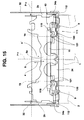
- the cassette erroneous insertion preventing mechanism 111 has a pair of rotational right and left cassette identification members 9 formed of synthetic resin or the like, a cassette insertion guide 10 and control levers 112.
- the cassette identification members 9, the cassette insertion guide 10 and the control levers 112 are secured to the front base 34 through support pins 113, 46 (common to the cassette double insertion preventing lid 45) and 114 respectively so as to be freely rotatable in the directions of arrows n,n' corresponding to the upward and downward directions, in the directions of arrows o,o' and in the directions of arrows p,p' respectively.
- the cassette identification members 9 are rotationally urged in the direction of the arrow n' corresponding to the upward direction by an identification member spring corresponding to the rotational urging means which is formed of a torsional coil spring
- the cassette insertion guide 10 is rotationally urged in the direction of the arrow o corresponding to the downward direction by an insertion guide spring 116 corresponding to rotational urging means which is formed of a leaf spring
- the control lever 112 is rotationally urged in the direction of the arrow p corresponding to the downward direction by a control lever spring 117 corresponding to rotational urging means which is formed of a tension coil spring stronger than the identification member spring 115.
- the pair of right and left cassette identification members 9 are disposed at both the right and left sides inside the cassette insertion port 4, and the cassette insertion guide 10 and the pair of right and left control levers 112 are disposed at the positions which are displaced from the pair of right and left cassette identification members 9 toward the cassette insertion direction side (the arrow a direction side). Further, the cassette insertion guide 116 is disposed between the pair of right and left cassette identification members 9, and the pair of right and left control levers 112 are disposed at the right and left sides of the pair of right and left cassette identification members 9.
- a pair of right and left projections 118 which are brought into contact with and separated from a pair of right and left arms 112a which are integrally formed on the upper end of the right and left sides of the pair of right and left control levers 112, are formed at the right and left sides of the front end (the end portion in the arrow a' direction) of the bottom plate 6a of the cassette stage 6, and the control means 44 is constructed by the pair of right and left control levers 112 and the projections 118.
- a pair of right and left engaging pins 112b which are integrally formed onto the inside of the upper end of the pair of right and left control levers 112 are engaged with a pair of right and left engaging pieces 9a which are integrally formed in a substantially arcuate shape onto the outside of the upper ends of the pair of right and left cassette identification members 9, and the pair of right and left engaging pins 9b which are formed integrally onto the inside of the pair of right and left cassette identification members 9 are engaged with a pair of right and left engaging pieces 10a which are integrally formed in a substantially L-shaped form to both the right and left ends of the cassette insertion guide 10.
- the cassette insertion guide 10 is projected toward the cassette discharge direction side (the arrow a' direction side) from the pair of right and left support pins 46, and a pair of right and left projecting portions 119 are integrally formed at the right and left sides of the tip side of the cassette insertion guide 10.
- the end surfaces of the pair of right and left projecting portions 119 in the direction of the arrow a' are formed on the cassette stopper surface 120, and the inside surfaces of the pair of these right and left projecting portions 119 are formed on a pair of right and left cassette guide surfaces 121 to guide the small-size tape cassette 1 onto the stage center P 11 in the cassette stage 6.
- the pair of right and left cassette identification members 9 are rotated in the direction of the arrow n' corresponding to the upward and forward direction by the pair of right and left identification member springs 115, so that the pair of right and left cassette identification members 9 get into a cassette insertion space 43 from the lower side and projected from the direction of the arrow n' to the position which is closest to the cassette insertion port 4.
- the pair of right and left engaging pieces 10a of the cassette insertion guide 10 is pushed upwardly in the direction of the arrow n by the pair of right and left engaging pins 9b of the pair of right and left cassette identifying members 9 to rotate the cassette insertion guide 10 against the insertion guide spring 116 in the direction of the arrow o'. Accordingly, the pair of right and left 119 get into the cassette insertion space 43 at the position where it is displaced to the direction side of the arrow a by the pair of right and left cassette identification members 9. Accordingly, the cassette 6 is returned to the cassette insertion position P 1 , whereby the cassette identification members 9 and the cassette insertion guide 10 are upwardly moved in the direction of an arrow I to the operation position in the cassette insertion space 43.
- the small-size tape cassette 1 is brought into contact with the cassette stopper surface 120 of any one of the pair of right and left projecting portions 119 of the cassette insertion guide 10, whereby the erroneous insertion of the small-size tape cassette 1 or another similar tape cassette can be prevented in advance.
- the pair of right and left engaging pins 9b are disengaged from the pair of right and left engaging pieces 10a of the cassette insertion guide 10 in the direction of the arrow n at the same time, and the cassette insertion guide 10 is rotated in the direction of the arrow o by the insertion guide spring 116, whereby the pair of right and left projecting portions 119 are instantaneously pulled to the lower side of the cassette insertion space 43. Accordingly, the cassette insertion guide 10 can subsequently smoothly insert the large-size tape cassette 2 to the insertion reference position P 12 in the cassette stage 6 with no disturbance of the insertion of the large-size tape cassette 2 by the cassette insertion guide 10.
- the pair of right and left projections 118 of the cassette stage 6 are separated from the arms 112a of the pair of right and left control levers 112 in the direction of the arrow a.
- the pair of right and left control levers 112 are simultaneously rotated in the direction of the arrow p by the pair of right and left control lever springs 117, and the pair of right and left engaging pins 112b pushes the pair of right and left engaging pieces 9a of the pair of right and left cassette identification members 9 in the direction of the arrow p.
- the pair of right and left cassette identification members 9 are rotated in the direction of the arrow n against the pair of right and left identification member springs 115, so that the cassette insertion guide 10 is rotated in the direction of the arrow of the insertion guide spring 116.
- the pair of right and left cassette identification members 9 and the cassette insertion guide 10 are descended in the direction of an arrow i' to the lower side of the cassette insertion space 43 from the operation position where they are ascended in the cassette insertion space 43 by the pair of right and left control levers 112, and accommodated at the accommodation position in the front base 34. Thereafter, the pair of right and left control levers 112 are locked at the rotational position in the direction of the arrow p as they are by the pair of right and left control lever springs 117. Therefore, the pair of right and left cassette identification members 9 and the cassette insertion guide 10 are locked at the accommodation position in the front base 34 as they are.
- the pair of right and left cassette identification members 9 and the cassette insertion guide 10 are downwardly pulled to the lower side of the cassette insertion space 43, and accommodated in the front base 34. Accordingly, it has a very good outward appearance, and even when a finger or the like is carelessly inserted through the cassette insertion port 4, it is hard to come into contact with the cassette identification members 9 or the cassette insertion guide 10.
- the support pins 113 of the cassette identification members 9 and the support pins 114 of the control levers 112 are separately disposed and the acting point distance L 11 from the support pin 114 of the control lever 112 is set to be longer that the acting point distance L 12 from the support pin 113 of the cassette identification member 9 to the engaging pin 9b, whereby a rotational angle of the control levers 112 which is required to rotate the cassette identification members 9 can be reduced.
- the depth dimension of the overall cassette erroneous insertion preventing mechanism 11 in the direction of the arrow a,a' can be greatly reduced, and thus the depth dimension of the cassette stage 6 in the directions of the arrows a,a' can be increased.
- the loading and ejecting operations of the large-size tape cassette 2 can be performed with high stability.
- the arms 112a of the control lever 112 can be shortened, and the friction area between the arms and the projections 118 of the cassette stage 6 can be reduced, so that resistance to wear can be enhanced.
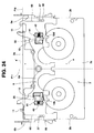
- a pair of right and left stopper blocks 12 which are formed of synthetic resin or the like and molded in a symmetrical shape at the right and left sides are inserted into the pair of right and left openings 35 which are formed in the bottom plate 6a of the cassette stage 6, and disposed so as to be equally shared to the right and left sides with respect to the stage center P 11 .
- Both the right and left side ends which corresponds to the outsides of the pair of right and left stopper blocks 12 are fixed between a pair of projection pieces 36 which are vertically bent downwardly from the bottom plate 6a by a pair of right and left horizontal support pins 41 so as to be freely rotatable in the directions of the arrows h,h' which correspond to the upward and downward directions.
- a pair of right and left cassette guides 12a are symmetrically formed integrally onto the upper surfaces of the pair of right and left stopper blocks 12, and on these upper surfaces, a pair of right and left cassette stoppers 12b which comprise vertically-shaped ribs are integrally formed at the end portions of the cassette insertion direction side (the arrow a direction side) at the inner positions of the cassette guides 12a.
- the axial lines P 13 of the pair of right and left support pins 41 are set in the range of 0° to 90° with respect to the stage center P 11 which is the cassette insertion direction.
- the axial lines P 13 of the pair of right and left support pins 41 are set to have a taper angle ⁇ 11 so that they are tapered in the cassette insertion direction (the direction of the arrow a) with respect to the stage center P 11 .
- the pair of right and left stopper blocks 12 are designed so as to freely move into and out of the cassette stage 6 in the directions of the arrows h,h' from the lower side of the bottom plate 6a.
- the pair of right and left stopper blocks 12 are constructed as described above, and as shown in Fig. 25, before the cassette is inserted into the cassette stage 6, the pair of right and left stopper blocks 12 gets into the cassette stage 6 from the direction of the arrow h by the pair of right and left torsional coil springs 42, and these cassette stoppers 12b are upwardly projected to the position corresponding to a predetermined height H 11 .
- the height H 11 is set to be higher than the height at which the small-size tape cassette 1 is upwardly floated from the bottom plate 6a of the cassette stage 6 when it is loaded onto the plural cassette positioning pins 8 of the cassette mount position P 3 .
- the pair of right and left cassette guides 12a guide the right and left side surfaces 1b of the small-size tape cassette 1 to position the small-size tape cassette 1 onto the stage center P 11 , and also the pair of right and left cassette stoppers 12b are relatively inserted into the pair of right and left slits 65 of the small-size tape cassette in the direction of the arrow a' to position the front end 1a of the small-size tape cassette 1 to the insertion reference position P 12 .
- one cassette stopper 12b pushes the-lock lever 66 of the small-size tape cassette 1 in the direction of the arrow a' to release the lock of the front lid 1A
- the pair of right and left stopper blocks 12 are freely rotatably secured to the bottom plate 6a by the pair of right and left support pins 41 which are set in the range of 0° to 90° with respect to the stage center P 11 , and further the cassette stoppers 12b are offset-OF 1 upwardly with respect to the support pins 41. Therefore, even when the small-size tape cassette 1 violently collides against the pair of right and left cassette stoppers 12b, these cassette stoppers 12b are not escaped in the direction of the arrow h' which corresponds to the downward direction, and also the small-size tape cassette 1 can be received firmly. Accordingly, the front end 1a of the small-tape cassette 1 can be positioned to the insertion reference position P 12 with high precision at all times.
- the pair of right and left support pins 41 are designed to have a tapered angle ⁇ 11 so that they are tapered in the cassette insertion direction (the direction of the arrow a) as shown in Fig. 22, the small-size tape cassette 1 is brought into contact with the pair of right and left cassette stoppers 12b from the direction of the arrow a.
- the pair of stopper blocks 12 When a thrust force is applied to the pair of right and left stopper blocks 12 in the direction of the arrow a, the pair of stopper blocks 12 are mutually attractively approached to each other by the amount corresponding to the backlash of the pair of right and left support pins 41, and both the right and left side surfaces 1b of the small-size tape cassette 1 are pinched by the pair of cassette guides 12a from both the right and left sides, whereby the small-size tape cassette 1 can be positioned onto the stage center P 11 with high precision.
- the pair of right and left cassette guides 37 formed on the bottom plate 6a are relatively inserted from the direction of the arrow a' into the pair of right and left slits 65 of the large-size tape cassette 2, and the large-size tape cassette 2 is positioned onto the stage center P 11 .
- the pair of right and left cassette guide pieces 37 relatively pushes the pair of right and left lock levers 66 in the direction of the arrow a' to release the lock of the front lid 2A.
- the pair of right and left torsional coil springs 42 which serve to rotationally urge the pair of stopper blocks 12 in the direction of the arrow h may merely produce such a weak force as to support the dead weight of the stopper blocks 12, the force with which the pair of right and left stopper blocks 12 upwardly lifts the small-size and large-size tape cassettes 1, 2 under the reaction force of the these torsional coil springs, can be reduced extremely.
- the clamp force to press and fix the small-size and large-size tape cassettes 1,2 onto the bottom, plate 6a by the cassette press lever 92 can be sufficiently reduced.
- the insertion operation of the small-size and large-size tape cassettes 1,2 into the cassette stage 6 can be easily performed with very weak force, and also the small-size and large-size tape cassettes 1,2 can be easily inserted and accurately positioned to the insertion reference position P 12 .
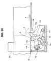
- the cassette slant insertion preventing mechanism 49 has a cassette slant insertion preventing stopper 48 and a lid opening/closing lever 131 which are formed of synthetic resin or the like.
- the front lid opening/closing lever 131 is secured to the right and left side plates 6b of the cassette stage 6 through a pair of right and left horizontal support pins so as to be freely rotatable in the directions of arrows k,k' corresponding to the upward and downward directions, and the rear end (the end portion of the arrow a direction side) 48a of the cassette slant insertion preventing stopper 48 is secured to the upper end 131a of the front lid opening/closing lever 131 through a pair of right and left horizontal support pins 133 so as to be freely rotatable in the directicns of arrows q,q' corresponding to the upward and downward directions.
- a hook portion 131b which is commonly engageable with the front lids 1A,2A of the small-size and large-size tape cassettes 1,2 from the lower side is integrally formed at the position which is at the lower end side of the front lid opening/closing lever 131 and near to the center thereof.
- plural engaging projections 48a onto the top plate portion 92b of the cassette press lever 92 which serves as a stopper support portion are integrally formed to the front end (the end portion in the arrow a' direction side) of the cassette slant insertions preventing stopper 48 so as to be spaced from one another at intervals in the right and left directions.
- Plural guide surfaces 48b are formed so as to extend from the plural projections 48a to the lower surface of the cassette insertion preventing stopper 48, and plural semi-circular projections 48c which abut against the lower surface of the chassis top plate 33 serving as a stopper press portion are integrally formed on the upper surface of the cassette slant insertion preventing stopper 48 so as to be spaced from one another at intervals in the right and left direction.
- the cassette slant insertion preventing stopper 48 and the front lid opening/closing lever 131 are rotated in the direction of the arrow k' due to their dead weight, and the plural projections 48a of the cassette slant insertion preventing stopper 48 are mounted on the top plate portion 92b.
- the small-size and large-size tape cassettes 1,2 are selectively inserted from the cassette insertion port 4 in the direction of the arrow a.
- the small-size and large-size tape cassettes 1,2 are obliquely inserted at an upwardly oblique angle ⁇ 1 with respect to the horizontal reference as indicated by a solid line when the tape cassettes 1,2 are selectively inserted into the cassette stage 6 in the direction of the arrow a while the opening/closing lid 5 is pushed and opened in the direction of the arrow c by these tape cassettes 1,2, the front lids 1A,2A of the small-size and large-size tape cassettes 1,2 are brought into contact with the plural guide surfaces 48c of the cassette slant insertion preventing stoppers 48 obliquely from the lower side to thereby push up the cassette slant Insertion preventing stopper 48 in the direction of the arrow q'.
- the front lids 1A,2A of the small-size and large-size tape cassettes 1,2 are guided by the plural guide surfaces 48a, and held down in the direction of the arrow r corresponding to the forward and downward direction, thereby preventing the slant insertion of the small-size and large-size tape cassettes 1,2 into the cassette stage 6 in advance.
- the small-size and large-size which are selectively inserted into the cassette stage 6 are horizontally pressed and fixed onto the bottom plate 6a by the cassette press force of the cassette press lever 92. After the cassette insertion, when the small-size and large-size tape cassettes 1,2 are selectively loaded to the cassette mount position P 3 from the direction of the arrow b as shown in Fig.
- the front lid opening/closing lever 131 is relatively pushed up in the direction of the arrow b' by the front lid opening/closing plate 134 which is integrally formed with one rack guide 73 and fixed at a fixed position, whereby the front lid opening/closing lever 131 is rotated in the direction of the allow k.
- the cassette slant insertion preventing stopper 48 is pushed out in the direction of the arrow k by the front lid opening/closing lever 131, and the cassette slant insertion preventing stopper 48 is pushed up from the direction of the arrow k onto the top plate portion 92b of the cassette press lever 92 by the guide surface 48.
- a part of the front lid 1A,2A of the small-size and large-size tape cassettes 1,2 is hooked by a hook portion 131b of the front opening/closing lever 131, whereby the front lids 1A, 2A are opened in the direction of the arrow k.
- the front opening/closing lever 131 can smoothly open the front lids 1A, 2A while retracting the cassette slant insertion preventing stopper 48 from the inside of the opening/closing space S 1 in the direction of the arrow k rearwardly and upwardly.
- the small-size and large-size tape cassettes 1,2 which are selectively loaded from the direction of the arrow b to the cassette mount position P 3 are selectively held onto the plural cassette positioning pins 8 at the cassette mount position P 3 through the common reference hole 14, whereby the small-size and large-size tape cassettes 1,2 are pushed up (floated) to the height H 1 above the bottom plate 6a of the cassette stage 6.
- the small-size and large-size tape cassettes 1,2 are accurately pressed and horizontally fixed onto the plural cassette positioning pins 8 by the cassette press force of the cassette press lever 92.
- a cassette insertion and type detection mechanism 14 for selecting the insertion position and type of the small-size and large-size tape cassettes 1,2 which are selectively inserted into the cassette stage 6 is secured to the lower portion of the bottom plate 6a of the cassette stage 6.
- the cassette insertion and type detection mechanism 141 is designed so that as shown in Figs. 3 and 4, the common detection target portions 15, 16 at one end side of the respective pairs of right and left detection target portions 15,16 which are formed in the small-size and large-size tape cassettes 1,2 are detected by one common detection lever 51, and the first and second detection target portions which are arranged at different positions at the other end side are detected by a double lever mechanism 55 comprising first and second detection levers 51 and 52.
- the two detection levers 51 which are symmetrical between the right and left sides are formed of metal plates or the like, and the second detection lever 52 at the double lever mechanism 55 is formed of synthetic resin or the like.
- One detection lever 51 and the first and second detection levers 51, 52 of the double lever mechanism 55 are fixed in the neighborhood of both the right and left ends of the lower portion of the bottom plate 6a of the cassette stage 6 through the vertical support pins 142 so as to be freely rotatable symmetrically in the directions of the arrows e,e' on the horizontal plane. Accordingly, the first and the second detection levers 51, 52 of the double lever mechanism 55 are freely rotationally secured to the common support pin 142.
- the two detection levers 51 at both the right and left sides are rotationally urged in the direction of the arrow e' by the pair of right and left tension coil springs 144 serving as the rotational urging means
- the second detection lever 52 of the double lever mechanism 55 is rotationally urged in the direction of the arrow e' by the torsion coil spring 145 serving as the rotational urging means.
- a pair of light reflection type optical sensors 22 are secured to the lower portion of the bottom plate 6 at the side of one detection lever 51 while the sensors are put face down
- two pairs of light reflection type optical sensors 22, 23 for detecting the positions of the first and second detection levers 51 and 52 respectively are secured to the lower portion of the bottom plate 6a at the side of the double lever mechanism 55 while the sensors are put face down.
- light reflection plates 56 and 57 are secured to the totally three detection levers 51 and 52, and a projection 53 for pushing the first detection lever 51 in the direction of the arrow e and an optical shutter 54 for inhibiting the operation of the optical sensor 22 for detecting the position of the first detection lever 51 are integrally formed with the second detection lever 52 of the double lever mechanism 55.
- the optical shutter 54 is designed so as to be movable in a space between the optical sensor 22 and the light reflection plate 56 in the directions of the arrows e,e'.
- one end 51a which is the inner side end of each of the two detection levers 51 at both the right and left sides is constructed as a detection portion
- the projection 53 in the second detection lever 52 of the double lever mechanism 55 is constructed as a detection portion.
- the one ends 51a of the two detection levers 51 and the projection 58 of the second detection lever 52 are vertically projected into the cassette stage 6 at the front side of the front end (the end portion in the arrow a direction side) of the bottom plate 6a of the cassette stage 6.
- the pair of right and left light reflection plates 56 of the pair of right and left detection levers 51 are moved to the lower side of the pair of right and left optical sensors 22, so that the pair of right and left optical sensors 22 are turned on to detect the rotational positions of the pair of right and left detection levers 51 by the pair of right and left optical sensors 22, thereby simultaneously performing the type detection indicating that the inserted cassette is a small-size tape cassette 1 and the insertion position detection indicating that the small-size tape cassette 1 is correctly inserted to the insertion reference position.
- the pair of right and left detection target portions 16 of the large-size tape cassette 2 abuts against the one end 51a serving as the detection portion of one detection lever 51 and the projection 53 serving as the detection portion of the second detection lever 52 of the double lever mechanism 55 from the direction of the arrow a.
- the one detection lever 51 is simply rotated in the direction of the arrow e in the same manner as described above, and one optical sensor 22 is turned on.
- the second detection lever 52 is first rotated against the torsion coil spring 145 in the direction of the arrow e around the common support pin 142.
- the optical shutter 54 of the second detection lever 52 preferentially moves to the lower side of the optical sensor 22 in a space between the optical sensor 22 and the light reflection plate 56 to inhibit the operation of the optical sensor 22 (to inhibit the shift from OFF to ON and lock the optical sensor to OFF state), and at the same time the projection 53 of the second detection lever 52 abuts against the projection 58 of the first detection lever 51 from the direction of the arrow e to push and move the first detection lever 51 against the tension coil spring 144 around the common support pin 142 in the direction of the arrow e.
- the light reflection plate 57 of the second detection lever 52 is moved to the lower side of the optical sensor 23 to turn on the optical sensor 23, and the rotational position of the second detection lever 52 is detected by the optical sensor 23.
- the light reflection plate 56 of the first detection lever 51 which is pushed and moved in the direction of the arrow e is also moved to the lower side of the optical sensor 22.
- the optical shutter 54 which preferentially moves has stopped below the optical sensor 22, so that the optical sensor 22 is kept in OFF state.
- the two optical sensors 22 and 23 are turned on to simultaneously perform the type detection indicating that the inserted cassette is a large-size tape cassette 2 and the insertion position detection indicating that the large-size tape cassette 2 is correctly inserted to the insertion reference position P 12 .
- the second detection lever 51 is pushed and moved in the direction of the arrow e by the projection 53 of the first detection lever 52, as shown in Figs.
- the rotational angle of the first detection lever 51 in the direction of the arrow e is increased, and the one end 51a thereof is separated in the direction of the arrow a from the front lid 2A of the large-size tape cassette 2, thereby forming a gap 24 therebetween. Accordingly, when the large-size tape cassette 2 is loaded to the cassette mount position P 3 to open the front lid 2A after the cassette insertion as described above, or when the large-size tape cassette 2 is ejected from the cassette mount position P 3 to close the front lid 2a, the front lid 2A can be smoothly opened/closed with no interference with the one end 51a of the first detection lever 51.
- the insertion position detection and the type detection of the small-size and large-size tape cassettes 1,2 can be performed by commonly applying the first and second detection levers 51, 52 of the double lever mechanism 55 to these cassettes. Therefore, the number of parts and the number of steps can be reduced, and the saving of the space and the reduction of the cost can be performed.
- the second detection lever 52 performs the insertion position detection and the type detection of the large-size tape cassette 2
- the operation of the optical sensor 22 for the first detection lever 51 which is used to perform the insertion position detection and the type detection of the small-size tape cassette 1 is inhibited by the optical shutter 54 of the second detection lever 51.
- the optical sensors 22, 23 used for the cassette insertion and type detection mechanism 141 are not limited to the light reflection type optical sensors, but a light transmission type optical sensor may be used.
- the pair of right and left detection levers 51 and 52 are also used as a cassette discharge lever, and in the following description, these detection levers 51, 52 are described as cassette discharge levers 51, 52.
- the pair of right and left cam driven levers 28 for driving the pair of right and left cassette discharge levers 51, 52 are secured to the pair of right and left side plate portions 92a of the cassette press lever 92 in the cassette stage 6 through tie pair of right and left horizontal support pins 29 so as to be freely rotatable in the directions of the arrows g,g' on the vertical plane.
- the pair of right and left cam driven levers 28 are suspended at the lower side of the pair of right and left support pins 29, and the pair of cams 31 comprising rollers are rotationally freely secured in a horizontal moving locus of the directions of the arrows a,a' of the lower ends 28a of the pair of right and left cam driven levers 28 inside the pair of right and left chassis side plates 32 shown in Figs. 4 to 8.
- a pair of right and left cam driven levers 28 are formed of synthetic resin, and a contact portion 39 to the other end 51b of the cassette discharge lever 51 is integrally formed at the inside position of the lower end 28a which is brought into contact with the cam 31, and the a leaf spring portion 38 which is bent substantially upwardly in a wavelike form from the side surface of the arrow g direction side of the contact portion 39. Further, a stopper pin 38a which is in parallel to the axial direction of the support pin 29 is integrally formed at the upper end of the leaf spring portion 38, and a securing hole 28b for the support pin 29 is formed at the upper end of each of the pair of right and left cam driven levers 28.
- two stoppers 40a, 40b for positionally regulating the stopper pins 38a within a fixed range at two positions on the peripheries of the support pins 29 are formed at the lower end edges of the pair of right and left side plates 92a of the cassette press lever 92 to which the pair of right and left cam driven levers 28 are freely rotationally secured through the pair of right and left support pins 29.
- the leaf spring portion 38, the stopper pin 38a and the two stoppers 40a, 40b constitute the control means 50 for positionally regulating the cam driven levers 28 at the intermediate position within its swing range and with some degree of freedom in a fixed range.
- the swing range ⁇ 11 shown in Fig. 46 is set so that the lower end 28a of the cam driven lever 28 can keep a suitable over-lap amount OV with the cam 31 which is horizontally moved relatively in the directions of the arrows a, a', and also the cam driven lever 28 can be smoothly rotated in the directions of the arrows g,g' by the cam 31 which is horizontally moved relatively in the directions of the arrows a,a', and the control means 50 serves to positionally regulate the cam driven lever 28 at the intermediate position within the swing range ⁇ 11 , and with some degree of freedom within a fixed range ⁇ 12 .
- the cassette discharge mechanism As shown in Figs. 34 and 35, when the small-size and large-size tape cassettes 1, 2 are selectively inserted from the direction of the arrow a to the insertion reference position P 12 in the cassette stage 6, the pair of right and left cassette discharge levers 51 are symmetrically rotated in the direction of the arrow e, and the small-size and large-size tape cassettes 1,2 are pressed and fixed onto the bottom plate 6a of the cassette stage 6 by the cassette press force of the cassette press lever 92, whereby the pair of right and left cassette discharge levers 51 are stopped at the rotational position in the direction of the arrow e.
- the cam driven lever 28 is further rotated in the direction of the arrow g from the stop position indicated by a one-dotted chain line to get over the cam 31.
- the leaf spring portion 38 is slacked against elasticity , and the restoring force of the cam driven lever 28 in the direction of the arrow g' is charged to the leaf spring portion 38.
- the cam driven lever 28 At the instantaneous time when the cam driven lever 28 gets over the cam 31 moving relatively in the direction of the arrow a', the cam driven lever 28 is rotationally returned in the direction of the arrow g' by the restoring force charged to the leaf spring portion 38. However, at the instantaneous time when the cam driven lever 28 passes over the stop position indicated by a one-dotted chain line in the direction of the arrow g', the stopper pin 38a is separated from the stopper 40a in the direction of the arrow g', and the restoring force of the cam driven lever 28 in the direction of the arrow g' by the leaf spring portion 38 is extinguished.
- the reverse rotational force of the cam driven lever 28 in the direction of the arrow g' is very weak, and the cam driven lever 28 is highly stably stopped at the stop position indicated by the solid line at the instantaneous time when the cam driven lever 28 is rotated in the direction of the arrow g' until the stop position indicated by the solid line and the stopper pin 38a abuts against the stopper 40.
- the gap 27 is kept between the contact portion 39 of the cam driven lever 28 which is reversely rotated in the direction of the arrow g' and the other end 51b of the cassette discharge lever 51, and the contact portion 39 of the cam driven lever 28 does not abut against the other end 51b of the cassette discharge lever 51 from the direction of the arrow g'. Even if the contact portion 39 abuts against the other end 51b in the direction of the arrow g', the impact at that time is very weak, and thus there occurs no uncomfortable impact sound "click sound".
- the cam driven lever 28 can be formed of synthetic resin or the like, and it can be manufactured at a low cost.
- the contact portion 39 of the cam driven lever 28 strongly pushes the other end 51b of the cassette discharge lever 51, and the pair of right and left cassette discharge levers 51 are simultaneously rotated in the direction of the arrow e', whereby the small-size and large-size tape cassettes 1,2 in the cassette stage 6 are discharged in the direction of the arrow a' by a fixed distance.
- the discharge stroke of the small-size and large-size tape cassettes 1,2 in the direction of the arrow a' is dependent on the thickness T 1 , T 2 , etc. of these tape cassettes 1,2.
- the discharge stroke of the small-size tape cassette 1 is set to be large, and the discharge stroke of the large-size tape cassette 2 is set to be small. As shown in Fig.
- the cassette type recording and reproducing apparatus of the present invention has the following effects.
- a cassette type recording and reproducing apparatus in that in a tape cassette ejecting operation, the cam driven lever is kicked by the cam, and the cassette discharge lever is rotated by the kicked cam driven lever, whereby the tape cassette in the cassette stage is pushed out in the cassette discharge direction by the cassette discharge lever is provided with control means for positionally regulating the cam driven lever with some degree of freedom in a fixed range and at the intermediate position of the swing range in which the cam driven lever is rotated by the cam.
- the cam driven lever violently collides against the cassette discharge lever in the course of the cassette loading operation to produce an uncomfortable sound "click sound"
- the tape cassette in the cassette stage is pushed and displaced by the cassette discharge lever due to the impact of the collision, so that the tape cassette cannot be accurately mounted to the plural cassette positioning pins (not shown) at the cassette mount position to induce a cassette loading miss.
- no special countermeasure to increase the clamp force of the tape cassette in the cassette stage is unnecessary, and rather the camp force ca be sufficiently reduced. Accordingly, the tape cassette may be discharged with a weak force by the cassette discharge lever at the eject time, and the rigidity of the cassette discharge lever and the cam driven lever is not necessary to be increased, so that reduction in cost and enhancement in reliability can be achieved.
- the cam driven lever is formed of synthetic resin or the like, and the cam driven lever is positionally regulated with some degree of freedom in a fixed range by the leaf spring portion which is integrally formed with the cam driven lever and the plural stoppers which are formed in the cassette stage, so that the cam driven lever can be positionally regulated accurately with some degree of freedom in the fixed range with a small number of parts and a small number of fabrication steps and in a simple structure.
- the cassette insertion port of the front panel is closed by the opening/closing lid secured to the cassette stage, and the cassette double insertion preventing lid is evacuated to the lid opening position.
- the cassette double insertion preventing lid is moved from the lid opening position to the lid closing position so that the inside of the cassette insertion port is closed by the cassette double insertion preventing lid. Therefore, the cassette double insertion, etc. can be prevented in advance when the tape cassette has been loaded, thereby enhancing the safety of the apparatus.
- the opening/closing lid is also used as the cassette press member for pressing the tape cassette in the cassette stage, so that the number of parts and the number of fabrication processes can be reduced, and the cost can be reduced.
- the cassette double insertion preventing lid is opened/closed by the opening/closing mechanism which is driven by the cassette loading mechanism, so that the loading motor is also used as the cassette double insertion preventing lid to perform the opening/closing operation and thus the construction can be simplified.
- the cassette double insertion preventing lid can be opened/closed at a good timing which is synchronized with the movement of the cassette stage, and thus there occurs no risk that the cassette stage and the cassette double insertion preventing lid collide against each other and thus they are damaged together, resulting in enhancement of the safety.
- the apparatus is designed so that the front lid portion of the tape cassette into which the cassette slant insertion preventing stopper secured to the cassette stage is inserted is relatively pushed from the upper side to prevent the forwardly and upwardly slant insertion of the tape cassette into the cassette stage in advance. Therefore, there never occurs such a loading miss that the tape cassette is loaded while it is carelessly obliquely inserted into the cassette stage, and the reliability and safety are enhanced.
- the cassette slant insertion preventing stopper is escaped to the upper side of the cassette stage, so that the front lid of the tape cassette can be smoothly opened with no interference with the cassette slant insertion preventing stopper.
- the cassette slant insertion preventing stopper when the cassette stage is moved to the cassette insertion position, the cassette slant insertion preventing stopper is burrowed into the lower side of the top plate of the chassis. Therefore, when the cassette slant insertion preventing lever is about to be pushed up by the tape cassette which is inserted in the forwardly upwardly slant direction into the cassette stage, the cassette slant insertion preventing stopper abuts against the top plate of the chassis to prevent the cassette slant insertion preventing stopper from being upwardly floated. Therefore, it is not necessary to support the cassette slant insertion preventing stopper with a complicated mechanism, so that the construction can be simplified and the cost can be reduced.
- the cassette slant insertion preventing stopper when the cassette stage is moved to the cassette mount position, the cassette slant insertion preventing stopper is escaped onto the mount table of the cassette stage. Therefore, when the tape cassette is loaded to the cassette mount position, the tape cassette is prevented from interfering with the cassette slant insertion preventing stopper even when it is floated upwardly from the cassette stage.
- the cassette slant insertion preventing stopper is freely rotatably secured to the front lid opening/closing lever which is freely rotatably secured to the cassette stage. Therefore, when the tape cassette is loaded to the cassette mount position by the cassette stage and the front lid of the tape cassette is upwardly opened by the front lid opening/closing lever, the cassette slant insertion preventing stopper can be easily escaped out of the front lid opening/closing space by the front lid opening/closing lever, so that the front lid opening/closing lever can be also used as the driving lever of the cassette slant insertion preventing stopper. Accordingly, the number of parts and the number of fabrication steps can be reduced, and the cost can be also reduced.
- the accommodation control means when the cassette stage is moved from the cassette insertion position to the cassette mount position side, the accommodation control means is actuated to automatically accommodate the cassette insertion guide and the cassette identifying member from its operation position in the cassette insertion space to the accommodation position out of the cassette insertion space. Therefore, under the cassette loading state, the cassette insertion guide and the cassette identifying member are little seen from the outside of the cassette insertion port.
- the outward appearance is remarkably better, and there can be beforehand prevented such an accident that an operator carelessly touches the cassette insertion guide, the cassette identifying member or the like to carelessly jump out these members from the cassette insertion space, so that the tape cassette carelessly collides against the cassette insertion guide, the cassette identifying member or the like in the cassette eject operation, and damages these members. Therefore, the reliability and safety can be more enhanced.
- the control lever when the cassette stage is moved from the cassette insertion position to the cassette mount position, the control lever is driven by the control lever urging means so that the cassette identifying member and the cassette insertion guide which are moved to the operation position in the cassette insertion space are accommodated at the accommodation position out of the cassette insertion space. Therefore, the cassette insertion guide and the cassette identifying member can be accommodated at the accommodation position out of the cassette insertion space in the cassette loading operation with a simple construction.
- the control lever and the cassette insertion guide are driven by the urging means to perform the accommodation operation. Therefore, the operation can be surely performed, and these members are never jumped out of the cassette insertion space even when the operator carelessly touches these members. Accordingly, the reliability and the safety can be more enhanced.
- the two cassette identifying members are disposed at two positions which are in the neighborhood of both the right and left ends of the cassette insertion port, and the cassette insertion guide is escaped out of the cassette insertion space only when the pair of right and left cassette identifying members are simultaneously driven by the large-size tape cassette. Therefore, even when only one of the cassette identifying members is driven to erroneously insert the small-size tape cassette or the like from a position which is greatly deviated to the right or left side of the cassette insertion port, the erroneous insertion of the small-size tape cassette can be surely prevented by the cassette insertion guide, and thus the reliability is very high.
- the thirteenth aspect of the present invention when plural types of tape cassettes which are different in size are selectively inserted into the cassette stage, two detection targets which are formed at different positions with respect to the positioning reference holes which are common to these tape cassettes are detected by the two detection levers of the double lever mechanism respectively, whereby the insertion position detection and the type detection of the tape cassette are simultaneously performed.
- the first detection lever is pushed by the second detection lever to move the first detection lever to a position where it does not interfere with the large-size tape cassette.
- the operation of the position detecting optical sensor of the first detection lever is inhibited by an optical shutter plate of the second detection lever.
- the insertion position detection and the type detection of the tape cassette can be simultaneously performed by only the two detection levers and the optical sensor. Accordingly, the cost can be reduced and the space can be saved because the number of parts and the number of fabrication steps can be reduced, and also the reliability can be enhanced because the number of optical sensors is reduced. Further, when a large-size tape cassette is detected, the first detection lever is pushed by the second detection lever, and the operation of the optical sensor for detecting the first detection lever is inhibited by the optical shutter of the second detection lever. Therefore, it is unnecessary to adjust the position of the optical sensor, and thus the fabrication is facilitated.
- the first and second detection levers are freely rotatably fixed around the common supporting pins of the cassette stage, so that the number of parts and the number of fabrication steps are reduced, and thus the cost can be reduced.
- the first detections lever is also used as a cassette discharge lever, so that the number of parts and the number of fabrication steps can be reduced, and thus the cost can be reduced.
- the pair of right and left stopper blocks are freely rotatably secured to the cassette stage by the pair of right and left supporting pins. Therefore, these stopper blocks never suffers deformation such as distortion or the like due to external force, and the pair of right and left rotational urging means may merely produce weak force with which the dead weight of the stopper blocks can be supported. Accordingly, in the case where the large-size tape cassette is inserted into the cassette stage, the pair of right and left stopper blocks can be easily escaped out of the cassette stage, and the large-size tape cassette can be easily inserted into the cassette stage with the weak force.
- the supporting pins of the pair of right and left stopper blocks are set in the range of 0 to 90 degrees with respect to the insertion direction. Therefore, when the small-size tape cassette is positioned to the insertion reference position by the pair of right and left cassette stoppers, the pair of right and left stopper blocks are hardly escaped, and thus the small-size tape cassette can be positioned with high precision.
- the pair of right and left stopper blocks are formed with slant surfaces for escape from the large-size tape cassette. Therefore, not only the force of the rotational urging means can be weakened, but also the insertion of the large-size tape cassette into the cassette stage can be easily performed with weak force.
- the pair of right and left stopper blocks are freely rotatably secured to the lower portion of the bottom plate of the cassette stage by the pair of right and left supporting pins disposed at the outside of these stopper blocks in the right and left directions, and the cassette guides and the cassette stoppers are offset upwardly from the pair of right and left supporting pins in such a state that the cassette guides and the cassette stoppers of the pair of right and left stopper blocks are projected to the upper side of the bottom plate by the pair of right and left rotational urging means.
- the pair of right and left stopper blocks are upwardly rotationally urged, and thus they are not escaped downwardly, so that the small-size tape cassette can be positioned with high precision.
Landscapes
- Automatic Tape Cassette Changers (AREA)
- Packaging Of Annular Or Rod-Shaped Articles, Wearing Apparel, Cassettes, Or The Like (AREA)
Applications Claiming Priority (2)
| Application Number | Priority Date | Filing Date | Title |
|---|---|---|---|
| JP8117169A JPH09282752A (ja) | 1996-04-16 | 1996-04-16 | カセット式記録再生装置 |
| JP117169/96 | 1996-04-16 |
Publications (1)
| Publication Number | Publication Date |
|---|---|
| EP0802533A2 true EP0802533A2 (de) | 1997-10-22 |
Family
ID=14705159
Family Applications (1)
| Application Number | Title | Priority Date | Filing Date |
|---|---|---|---|
| EP97302573A Withdrawn EP0802533A2 (de) | 1996-04-16 | 1997-04-15 | Kassettenaufzeichnungs-/-wiedergabegerät |
Country Status (5)
| Country | Link |
|---|---|
| US (6) | US5854723A (de) |
| EP (1) | EP0802533A2 (de) |
| JP (1) | JPH09282752A (de) |
| KR (1) | KR970069466A (de) |
| CN (1) | CN1167976A (de) |
Cited By (1)
| Publication number | Priority date | Publication date | Assignee | Title |
|---|---|---|---|---|
| EP1089277A3 (de) * | 1999-09-30 | 2004-08-04 | Sony Corporation | Kassettenlaufwerk |
Families Citing this family (8)
| Publication number | Priority date | Publication date | Assignee | Title |
|---|---|---|---|---|
| KR19990003953A (ko) * | 1997-06-27 | 1999-01-15 | 윤종용 | 트레이 방식 자기기록재생기 |
| JP3308945B2 (ja) * | 1999-10-18 | 2002-07-29 | 米沢日本電気株式会社 | カートリッジの誤挿入防止機構 |
| JP2002279778A (ja) * | 2001-03-21 | 2002-09-27 | Orion Denki Kk | ビデオデッキにおける挿入口のドア装置 |
| US6961206B2 (en) * | 2002-08-28 | 2005-11-01 | Victor Company Of Japan, Ltd. | Cassette holder allowing large and small cassettes to be selectively loaded |
| US7097125B2 (en) * | 2003-06-27 | 2006-08-29 | Certance Llc | Tape drive with automatic adaptation for different size tape cassettes |
| US8045288B2 (en) * | 2003-11-11 | 2011-10-25 | Hitachi Maxell, Ltd. | Tape drive with cartridge thickness detecting sensors |
| JP4844018B2 (ja) * | 2005-06-15 | 2011-12-21 | ミツミ電機株式会社 | カートリッジホルダ装置 |
| KR101848063B1 (ko) | 2010-11-17 | 2018-04-12 | 삼성디스플레이 주식회사 | 액정 표시 장치 및 그 제조 방법 |
Family Cites Families (44)
| Publication number | Priority date | Publication date | Assignee | Title |
|---|---|---|---|---|
| JPS6340848U (de) * | 1986-08-30 | 1988-03-17 | ||
| JPH05983Y2 (de) * | 1986-09-11 | 1993-01-12 | ||
| JPH0652607B2 (ja) * | 1987-11-10 | 1994-07-06 | 日本ビクター株式会社 | 磁気記録/再生装置 |
| EP0334257B1 (de) * | 1988-03-23 | 1994-08-24 | Sony Corporation | Automatischer Videokassettenwechsler |
| JPH0229968A (ja) * | 1988-07-19 | 1990-01-31 | Sankyo Seiki Mfg Co Ltd | デープカセットのエジェクト装置 |
| US5121271A (en) * | 1988-10-31 | 1992-06-09 | Matsushita Electric Industrial Co., Ltd. | Cassette holder device capable of receiving large and small size cassettes |
| US5046169A (en) * | 1988-12-20 | 1991-09-03 | Sony Corporation | Magnetic tape cassette loading and guiding system |
| JP2625541B2 (ja) * | 1989-02-28 | 1997-07-02 | 株式会社日立製作所 | カセツト移送機構 |
| JPH02285546A (ja) * | 1989-04-27 | 1990-11-22 | Sony Corp | リール台シフト装置の移動台位置決め機構 |
| US5204792A (en) * | 1989-11-09 | 1993-04-20 | Wangtek, Inc. | Cartridge tape drive |
| GB2242057B (en) * | 1990-01-31 | 1994-07-27 | Gold Star Co | Ejecting and loading mechanism for cassette |
| JP2657562B2 (ja) * | 1990-02-14 | 1997-09-24 | アルプス電気株式会社 | テーププレーヤのイジェクト装置 |
| US5184261A (en) * | 1990-03-28 | 1993-02-02 | Sony Corporation | Various-sized-cassette housing shelf |
| KR930007441Y1 (ko) * | 1990-11-23 | 1993-10-25 | 삼성전자 주식회사 | Dat카세트의 리드개방보조장치 |
| KR930008279B1 (ko) * | 1991-01-30 | 1993-08-27 | 삼성전자 주식회사 | 카세트 홀더 |
| US5402286A (en) * | 1991-02-27 | 1995-03-28 | Funai Electric Co., Ltd. | Device for manipulating a shutter |
| JP3033225B2 (ja) * | 1991-03-13 | 2000-04-17 | ソニー株式会社 | テーププレーヤ |
| US5402405A (en) * | 1991-03-18 | 1995-03-28 | Sony Corporation | Cassette loading apparatus |
| JPH0528605A (ja) * | 1991-07-24 | 1993-02-05 | Matsushita Electric Ind Co Ltd | テープカセツト装着装置 |
| DE4129945A1 (de) * | 1991-09-09 | 1993-03-11 | Philips Patentverwaltung | Schwenkvorrichtung fuer eine abdeckklappe am kassettenschacht eines magnetbandkassettengeraetes |
| US5386329A (en) * | 1991-09-20 | 1995-01-31 | Victor Company Of Japan, Ltd. | Tape cassette loading system |
| JPH05128675A (ja) * | 1991-11-05 | 1993-05-25 | Sony Corp | カセツト・オートチエンジヤー |
| JP3276986B2 (ja) * | 1992-06-29 | 2002-04-22 | 日本電産コパル株式会社 | 開閉扉機構 |
| JP3204418B2 (ja) * | 1992-09-30 | 2001-09-04 | ソニー株式会社 | カセツト着脱装置 |
| US5497279A (en) * | 1993-04-16 | 1996-03-05 | Hitachi, Ltd. | Tape cartridge and recording reproduction apparatus for the tape cartridge |
| US5648882A (en) * | 1993-06-30 | 1997-07-15 | Mitsumi Electric Company, Ltd. | Front structure for magnetic recording system |
| KR0148625B1 (ko) * | 1993-07-02 | 1998-12-15 | 가나이 쯔또무 | 기록재생장치의 카세트 로딩기구 |
| JP2986318B2 (ja) * | 1993-11-30 | 1999-12-06 | キヤノン株式会社 | 磁気記録再生装置 |
| JPH0741735U (ja) * | 1993-12-24 | 1995-07-21 | ティアック株式会社 | カセットコンパートメント機構 |
| US5481520A (en) * | 1994-01-06 | 1996-01-02 | Shinano Kenshi Kabushiki Kaisha | Disk player door assembly |
| KR970701904A (ko) * | 1995-01-30 | 1997-04-12 | 제이. 지. 에이. 롤페 | 적어도 두개의 크기가 다른 카세트의 기록 및 재생 장치(Recording and/or reproducing apparatus for cassettes of at least two different sizes) |
| US5701216A (en) * | 1995-02-21 | 1997-12-23 | Asahi Kogaku Kogyo Kabushiki Kaisha | Shutter mechanism for disk drive cartridge insertion opening |
| US5748595A (en) * | 1995-03-30 | 1998-05-05 | Ricoh Company, Ltd. | Cartridge loading mechanism with a door closing assembly |
| JP3063573B2 (ja) * | 1995-06-02 | 2000-07-12 | 松下電器産業株式会社 | カセットローディング装置 |
| JP2636809B2 (ja) * | 1995-06-29 | 1997-07-30 | 日本電気株式会社 | 磁気テープ用カートリッジロード装置 |
| JPH0963258A (ja) * | 1995-08-18 | 1997-03-07 | Esuperia Kk | テープ再生装置 |
| KR0170305B1 (ko) * | 1995-11-08 | 1999-04-15 | 김광호 | 테이프 레코더의 프론트 도어 잠금장치 |
| KR0176551B1 (ko) * | 1995-12-22 | 1999-04-15 | 김광호 | 자기 기록/재생장치 |
| JPH09180326A (ja) * | 1995-12-26 | 1997-07-11 | Sony Corp | カセット式記録再生装置 |
| US5788174A (en) * | 1996-01-04 | 1998-08-04 | Staar S.A. | Centering mechanism for multi-cassette loading/unloading system |
| JP3417191B2 (ja) * | 1996-02-27 | 2003-06-16 | ソニー株式会社 | 記録再生装置 |
| US5822149A (en) * | 1996-02-27 | 1998-10-13 | Sony Corporation | Positioning guide mechanism and erroneous insertion detecting and discharging mechanism for a recording and producing apparatus |
| KR100198612B1 (ko) * | 1996-04-25 | 1999-06-15 | 전주범 | 테이프카세트 정전기 방지장치 |
| US5691860A (en) * | 1996-05-09 | 1997-11-25 | Avatar Systems Corp. | Self sealing structure for a removable disk hard disk drive |
-
1996
- 1996-04-16 JP JP8117169A patent/JPH09282752A/ja not_active Withdrawn
-
1997
- 1997-04-15 US US08/834,214 patent/US5854723A/en not_active Expired - Fee Related
- 1997-04-15 EP EP97302573A patent/EP0802533A2/de not_active Withdrawn
- 1997-04-16 CN CN97113099A patent/CN1167976A/zh active Pending
- 1997-04-16 KR KR1019970013956A patent/KR970069466A/ko not_active Withdrawn
-
1998
- 1998-03-26 US US09/048,931 patent/US5883756A/en not_active Expired - Fee Related
- 1998-10-02 US US09/165,731 patent/US5936797A/en not_active Expired - Fee Related
- 1998-10-02 US US09/165,723 patent/US5956202A/en not_active Expired - Fee Related
- 1998-10-02 US US09/165,320 patent/US6266206B1/en not_active Expired - Fee Related
- 1998-10-02 US US09/165,722 patent/US5949610A/en not_active Expired - Fee Related
Cited By (1)
| Publication number | Priority date | Publication date | Assignee | Title |
|---|---|---|---|---|
| EP1089277A3 (de) * | 1999-09-30 | 2004-08-04 | Sony Corporation | Kassettenlaufwerk |
Also Published As
| Publication number | Publication date |
|---|---|
| JPH09282752A (ja) | 1997-10-31 |
| KR970069466A (ko) | 1997-11-07 |
| US5854723A (en) | 1998-12-29 |
| US5936797A (en) | 1999-08-10 |
| US5883756A (en) | 1999-03-16 |
| US6266206B1 (en) | 2001-07-24 |
| US5956202A (en) | 1999-09-21 |
| US5949610A (en) | 1999-09-07 |
| CN1167976A (zh) | 1997-12-17 |
Similar Documents
| Publication | Publication Date | Title |
|---|---|---|
| US4680654A (en) | Lid locking mechanism for an automatic tape cassette loading and unloading apparatus | |
| US5883756A (en) | Cassette apparatus lid arrangement which prevents double insertion | |
| US4337487A (en) | Magnetic recording/reproducing apparatus | |
| US5793565A (en) | Cassette discriminating member, cassette insertion guide, cassette ejecting mechanism for a cassette type recording and reproducing apparatus | |
| US5021904A (en) | Tape cassette push-out device for tape recorder | |
| US6754039B2 (en) | Cassette loading apparatus | |
| US5400193A (en) | Cassette loading device | |
| KR0148625B1 (ko) | 기록재생장치의 카세트 로딩기구 | |
| US5249088A (en) | Cassette loading apparatus with resilient guide slot for prevention of jamming | |
| US5889632A (en) | Cassette loading apparatus | |
| KR100379050B1 (ko) | 디스크 장치 | |
| US20010028529A1 (en) | Disk cartridge, its door opening and closing mechanism and disk drive | |
| JPH05174470A (ja) | 磁気テープカセット用ローディング機構を有する磁気テープカセット装置 | |
| JP3417191B2 (ja) | 記録再生装置 | |
| JPH09282754A (ja) | カセット式記録再生装置 | |
| JPH048511Y2 (de) | ||
| JPS6025740Y2 (ja) | カセツト着脱装置の蓋装置 | |
| US20020024759A1 (en) | Magnetic tape device | |
| JP3516107B2 (ja) | カセット式記録再生装置 | |
| JPH09282755A (ja) | カセット式記録再生装置 | |
| JPH09282751A (ja) | カセット式記録再生装置 | |
| JPH09282756A (ja) | カセット式記録再生装置 | |
| KR100202826B1 (ko) | 비데오 테이프레코더의 프론트도어 개폐장치 | |
| JPH09180323A (ja) | カセット式記録再生装置 | |
| JPH03228251A (ja) | カセット装着装置 |
Legal Events
| Date | Code | Title | Description |
|---|---|---|---|
| PUAI | Public reference made under article 153(3) epc to a published international application that has entered the european phase |
Free format text: ORIGINAL CODE: 0009012 |
|
| AK | Designated contracting states |
Kind code of ref document: A2 Designated state(s): DE FR GB |
|
| STAA | Information on the status of an ep patent application or granted ep patent |
Free format text: STATUS: THE APPLICATION HAS BEEN WITHDRAWN |
|
| 18W | Application withdrawn |
Withdrawal date: 20020502 |