EP0802353A2 - Système de régulation de la pression des embrayages dans une transmission automatique pendant un sauté de vitesse - Google Patents
Système de régulation de la pression des embrayages dans une transmission automatique pendant un sauté de vitesse Download PDFInfo
- Publication number
- EP0802353A2 EP0802353A2 EP96120387A EP96120387A EP0802353A2 EP 0802353 A2 EP0802353 A2 EP 0802353A2 EP 96120387 A EP96120387 A EP 96120387A EP 96120387 A EP96120387 A EP 96120387A EP 0802353 A2 EP0802353 A2 EP 0802353A2
- Authority
- EP
- European Patent Office
- Prior art keywords
- shift
- speed
- friction engagement
- fluid pressure
- automatic transmission
- Prior art date
- Legal status (The legal status is an assumption and is not a legal conclusion. Google has not performed a legal analysis and makes no representation as to the accuracy of the status listed.)
- Ceased
Links
- 230000005540 biological transmission Effects 0.000 title claims description 48
- 239000012530 fluid Substances 0.000 claims abstract description 60
- 230000007246 mechanism Effects 0.000 claims description 66
- 230000001105 regulatory effect Effects 0.000 abstract description 12
- 230000033228 biological regulation Effects 0.000 abstract description 8
- 230000035939 shock Effects 0.000 abstract description 6
- 230000001276 controlling effect Effects 0.000 abstract description 2
- 230000008859 change Effects 0.000 description 13
- 238000010276 construction Methods 0.000 description 10
- 238000001514 detection method Methods 0.000 description 4
- 230000000694 effects Effects 0.000 description 3
- 230000009467 reduction Effects 0.000 description 3
- 230000001133 acceleration Effects 0.000 description 2
- 230000005764 inhibitory process Effects 0.000 description 2
- 230000004044 response Effects 0.000 description 2
- 238000005549 size reduction Methods 0.000 description 2
- 230000002159 abnormal effect Effects 0.000 description 1
- 230000015556 catabolic process Effects 0.000 description 1
- 230000007423 decrease Effects 0.000 description 1
- 238000006731 degradation reaction Methods 0.000 description 1
- 238000010586 diagram Methods 0.000 description 1
- 238000012986 modification Methods 0.000 description 1
- 230000004048 modification Effects 0.000 description 1
Images


Classifications
-
- F—MECHANICAL ENGINEERING; LIGHTING; HEATING; WEAPONS; BLASTING
- F16—ENGINEERING ELEMENTS AND UNITS; GENERAL MEASURES FOR PRODUCING AND MAINTAINING EFFECTIVE FUNCTIONING OF MACHINES OR INSTALLATIONS; THERMAL INSULATION IN GENERAL
- F16H—GEARING
- F16H61/00—Control functions within control units of change-speed- or reversing-gearings for conveying rotary motion ; Control of exclusively fluid gearing, friction gearing, gearings with endless flexible members or other particular types of gearing
- F16H61/04—Smoothing ratio shift
- F16H61/06—Smoothing ratio shift by controlling rate of change of fluid pressure
- F16H61/061—Smoothing ratio shift by controlling rate of change of fluid pressure using electric control means
-
- F—MECHANICAL ENGINEERING; LIGHTING; HEATING; WEAPONS; BLASTING
- F16—ENGINEERING ELEMENTS AND UNITS; GENERAL MEASURES FOR PRODUCING AND MAINTAINING EFFECTIVE FUNCTIONING OF MACHINES OR INSTALLATIONS; THERMAL INSULATION IN GENERAL
- F16H—GEARING
- F16H61/00—Control functions within control units of change-speed- or reversing-gearings for conveying rotary motion ; Control of exclusively fluid gearing, friction gearing, gearings with endless flexible members or other particular types of gearing
- F16H61/02—Control functions within control units of change-speed- or reversing-gearings for conveying rotary motion ; Control of exclusively fluid gearing, friction gearing, gearings with endless flexible members or other particular types of gearing characterised by the signals used
- F16H61/0202—Control functions within control units of change-speed- or reversing-gearings for conveying rotary motion ; Control of exclusively fluid gearing, friction gearing, gearings with endless flexible members or other particular types of gearing characterised by the signals used the signals being electric
- F16H61/0204—Control functions within control units of change-speed- or reversing-gearings for conveying rotary motion ; Control of exclusively fluid gearing, friction gearing, gearings with endless flexible members or other particular types of gearing characterised by the signals used the signals being electric for gearshift control, e.g. control functions for performing shifting or generation of shift signal
- F16H61/0206—Layout of electro-hydraulic control circuits, e.g. arrangement of valves
Definitions
- the present invention relates to an automatic transmission installed in a motor vehicle and, more particularly, to a transmission control apparatus capable of, during a shift operation, deciding and making a shift to another speed (overlap shift).
- a known automatic transmission comprises a main speed shift mechanism of three forward speeds and one reverse speed and an auxiliary speed shift mechanism of three speeds, and achieves multi-speeds, for example, five forward speeds and one reverse speed, by a combination of the main and auxiliary speed shift mechanisms.
- Such an automatic transmission may make a shift decision regarding one of the two shift mechanisms during a shift operation of the other shift mechanism.
- the automatic transmission may make a decision to shift to the 3rd speed (a second shift) by changing over the engagement of two friction engagement elements (by releasing a C3 clutch and engaging a B4 brake) of the auxiliary speed shift mechanism.
- a conventional automatic transmission disclosed in, for example, examined Japanese patent application publication No. HEI-5-50621, determines that the operation of shifting to the speed based on the first shift instruction has been completed on the basis of detection of the continuation of a state where the input and output rotational speed ratio at the speed achieved by the first shift instruction is approximately 1.0, over at least a predetermined length of time. If a second shift instruction, different from the first speed shift instruction, is given during the period between the output of the first shift instruction and the completion of the shift based on the first instruction, the automatic transmission prevents a shift operation based on the second shift instruction. That is, if during a first shift operation a second shift decision is made, the automatic transmission inhibits the second shift operation until the first shift operation is completed. This shift operation inhibition prevents deviation of the timing of engagement changeover of friction engagement elements, thus preventing a rapid engine speed lift or an abnormal engine speed reduction.
- a control apparatus of an automatic transmission comprising a control unit that inputs signals from sensors based on vehicle running conditions and that outputs hydraulic control signals to a plurality of hydraulic control means for controlling fluid pressure to hydraulic servos for a plurality of predetermined friction engagement elements.
- the control unit has overlap shift control means for, if during operation of a first shift a second shift is decided on the basis of signals from the sensors, outputting the hydraulic control signals so as to start servo-start of fluid pressure to friction engagement elements that are to be operated for the second shift so that pistons will stroke and the friction engagement elements will become a state to be assumed before transmitting toque, and so as to start the operation of the second shift when the servo-start is completed and a predetermined speed is substantially established by the first shift.
- the second shift decision is immediately followed by start of the servo-start of the fluid pressure to the friction engagement elements that are to be operated for the second shift.
- the control apparatus starts the operation of the second shift.
- the time lag is correspondingly reduced, thus reducing the shift time for a overlap-speed shift.
- the second shift operation is started after the servo-start has been completed and a predetermined speed has been substantially established by the first shift, there is no degradation in shift feels.
- the invention may have a preferred construction wherein the second shift is an engagement changeover shift that engages a first friction engagement element and releases a second friction engagement element, and wherein on the basis of decision to make the second shift, the servo-start of the fluid pressure to the first friction engagement element to be engaged is started, and the fluid pressure to the second friction engagement element to be released is maintained at a predetermined engaging pressure.
- the control apparatus performs the servo-start of the engaging-side fluid pressure and maintains the releasing-side fluid pressure at a predetermined engaging pressure before starting the second shift operation. After the servo-start, the second shift operation is performed by the engagement changeover.
- the invention is able to achieve good timing of the engagement changeover of the releasing and engaging friction engagement elements and prevents shift shocks.
- the first shift achieve the predetermined speed by releasing a third friction engagement element, and that a hydraulic servo for the third friction engagement element be connected in communication with an accumulator.
- control apparatus is able to smoothly continue releasing the third friction engagement element for the first shift operation by using the accumulator, thus reducing shift shocks.
- the capacity of the accumulator can be reduced compared with that of a typical accumulator for the conventional automatic transmission.
- the size reduction of the accumulator leads to a size reduction of the automatic transmission.
- control apparatus of the invention further comprises a changeover valve for switching fluid pressure from one of the plurality of hydraulic control means, over to the hydraulic servo for the third friction engagement element and to a hydraulic servo for the second friction engagement element. Based on the decision to make the second shift, the control apparatus switches the changeover valve so that a conduction destination of the fluid pressure from one of the plurality of hydraulic control means is switched from the hydraulic servo for the third friction engagement element to the hydraulic servo for the second friction engagement element.
- This construction enables the control apparatus to change over the pressure regulation control of the hydraulic servo of the third friction engagement element for the first shift, and the pressure regulation control of the hydraulic servo of the second friction engagement element for the second shift, by using only a single unit of hydraulic control means, that is, by switching over the changeover valve.
- the control apparatus of the invention thus eliminates the need to employ expensive hydraulic control means formed of, for example, a linear solenoid valve, and achieves a cost reduction.
- the automatic transmission comprises a main speed shift mechanism and an auxiliary speed shift mechanism
- the first shift is performed by changing the transmission path of one of the main speed shift mechanism and the auxiliary speed shift mechanism
- the second shift is performed by changing the transmission path of the other one of the main speed shift mechanism and the auxiliary speed shift mechanism.
- the invention is able to smoothly perform an overlap shift that involves the changing of both the transmission path of the main speed shift mechanism and the transmission path of the auxiliary speed shift mechanism.
- the control apparatus of the invention estimates an input torque occurring when the second shift is decided, and starts operation of the second shift by using a fluid pressure in accordance with the input torque.
- the input torque at the time of decision to make the second shift is determined by calculating a correction value from a difference between a throttle opening that serves as a basis for the hydraulic control of operation of the first shift and a throttle opening detected when the second shift is decided, and by correcting with the correction value an input torque that serves as a basis for the hydraulic control of operation of the first shift.
- a five-speed automatic transmission 1 comprises a torque converter 4, a three-speed main speed shift mechanism (section) 2, a three-speed auxiliary speed shift mechanism (section) 5 and a differential 13 (not shown) which are connected together and contained in an integrally built case.
- the torque converter 4 comprises a lockup clutch 4a and, therefore, transmits toque from an engine crank shaft 13 to the main speed shift mechanism 2 by the fluid flowing in the torque converter 4 or the mechanical connection achieved by the lockup clutch.
- the integral case rotatably supports a first shaft 3 (specifically, an input shaft), a second shaft 6 (counter shaft) disposed parallel to the first shaft 3, and a third shaft (right and left axle shafts).
- a valve body is disposed on the outer face of the case.
- the main speed shift mechanism 2 has a planetary gear unit 15 composed of a simple planetary gear set 7 and a double-pinion planetary gear set 9.
- the simple planetary gear set 7 is made up of a sun gear S1 formed of a long gear, a ring gear R1, and a carrier CR supporting pinions P1 meshed with the sun gear S1 and the ring gear R1.
- the pinions P1 are formed of long pinions.
- the double-pinion planetary gear set 9 is made up of the same sun gear S1, a ring gear R2, and the same carrier CR, which supports the same pinions P1 meshed with the sun gear S1 and pinions P2 meshed with the ring gear R2 so that the pinions P1 and the pinions P2 mesh.
- the input shaft 3 cooperatively connected to the engine crank shaft 13 by the torque converter 4 can be connected to the ring gear R1 of the simple planetary gear set 7 by a first (forward) clutch C1, and to the common sun gear S1 thereof by a second (direct) clutch C2.
- the sun gear S1 can be stopped directly by a first brake B1, and it can also be stopped by a second brake B2 by way of a first one-way clutch F1.
- the ring gear R2 of the double-pinion planetary gear set 9 can be stopped by a third brake B3 and also by a second one-way clutch F2.
- the common carrier CR is firmly connected to a counter drive gear 8 that serves as an output member of the main speed shift mechanism 2.
- the auxiliary speed shift mechanism (section) 5 comprises an output gear 16, a first simple planetary gear set 10 and a second simple planetary gear set 11 which are disposed in that order toward the rear along the axis of the counter shaft 6 forming the second shaft.
- the counter shaft 6 is rotatably supported on the integral case by bearings.
- the first and second simple planetary gear sets 10, 11 are of Simpson type.
- the ring gear R3 of the first simple planetary gear set 10 is connected to a counter driven gear 17 meshed with the counter drive gear 8.
- the sun gear S3 is fixed to a sleeve shaft 12 rotatably supported by the counter shaft 6.
- the pinions P3 are supported by a carrier CR3 formed by a flange firmly connected to the counter shaft 6.
- the carrier CR3, supporting the pinions P3 on the other side, is connected to an inner hub of a UD direct clutch C3.
- the sun gear S4 of the second simple planetary gear set 11 is connected to the sung gear S3 of the first simple planetary gear set.
- the ring gear R4 of the second simple planetary gear set 11 is connected to the counter shaft 6.
- the UD direct clutch C3 is disposed between the career CR3 of the first simple planetary gear set and the coupled sun gears S3, S4.
- the coupled sun gears S3, S4 can be stopped by a fourth brake B4 formed by a band brake.
- the career CR4 of the second simple planetary gear set supporting the pinions P4 can be stopped by a fifth brake B5.
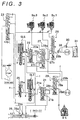
- FIG. 3 only shows the elements of a hydraulic circuit that are necessary to illustrate the operation of the embodiment and connected merely for such illustration, although the actual circuit has a more complicated construction comprising many more parts.
- So. 1, So. 2, So. 3 denote on-off controlled solenoid valves (normally closed) ; and SLS, SLT denote linear solenoid valves.
- the (first) solenoid valve SLS is provided solely for regulating the fluid pressure supply to various hydraulic servos.
- the (second) solenoid valve SLT is operated corresponding to the throttle opening based on the accelerator pedal operation by an operator, so as to mainly perform the function of regulating the throttle pressure.
- the (second) solenoid valve SLT also performs auxiliary pressure regulation for the hydraulic servos.
- a shift pressure control valve 20 and a B-4 control valve 21 have control fluid chambers 20a, 21a that receive the control pressure from output ports a, b of the linear solenoid valves SLS, SLT, respectively. Based on the control pressure, the control valves 20, 21 regulate the line pressure supplied into their input ports 20b, 21b and output the regulated pressure from the output ports 20c, 21c.
- the linear solenoid valve SLT provided mainly for throttle pressure control as described above, supplies the throttle pressure as a control fluid pressure to a primary regulator valve (described later) within a normal line pressure control operating range. In a marginal range beyond the normal line pressure control operating range, the pressure regulation of the B-4 control valve is performed.
- Fig. 3 further shows a hydraulic pump 22, a primary regulator valve 23 and a solenoid modulator valve 25.
- the primary regulator valve 23 regulates the fluid pressure from the hydraulic pump 22 to the line pressure and outputs it to a line pressure fluid passage c.
- the solenoid modulator valve 25 reduces the line pressure and supplies the fluid pressure from its output port 25a to the input ports d, e of the linear solenoid valves SLS, SLT.
- a manual valve 26 connects its line pressure port 26a to various ports corresponding to the shift position of a shift lever, for example, to its output port 26b if the shift lever is in the D, 4th, 3rd or 2nd position.
- Fig. 3 further shows a pressure relay valve 27, a second (M2) shift valve 28 for the main speed shift mechanism, and a first (U1) shift valve for the auxiliary speed shift mechanism, which form changeover means for changing over the supply of fluid pressure to the hydraulic servos C-2, C-3, B-4 for the second clutch, the third clutch and the fourth brake, and the discontinuation thereof.
- the second clutch hydraulic servo C-2 is connected in communication with a C2 accumulator 31 by an orifice 30 provided with a check valve.
- the C2 accumulator 31 has a relatively simple construction with a small capacity.
- Fig. 4 schematically illustrates an electronic control apparatus of the hydraulic control circuit.
- An electronic control unit U receives electric signals from an engine speed sensor 32, a throttle opening sensor 33, an automatic transmission input rotation speed (turbine speed) sensor 35, and a vehicle speed (output rotation speed) sensor 36.
- the control unit has overlap shift control means 37 for outputting signals to the three solenoid valves So.1, So.2, So.3 and the two linear solenoid valves SLS, SLT on the basis of the calculation by the control unit.
- the forward clutch C1 engages and the second one-way clutch F2 and the fifth brake B5 engage so that the ring gear R2 of the double-pinion planetary gear set and the carrier CR4 of the second simple planetary gear set 11 are maintained in stoppage.
- the rotation of the input shaft 3 is transmitted to the ring gear R1 of the simple planetary gear set by the forward clutch C1. Since the ring gear R2 of the double-pinion planetary gear set is held in the stopped state, the common carrier CR rotates in the forward direction at a considerably reduced speed while the sun gear S1 idles in the reverse direction.
- the main speed shift mechanism 2 is in the first speed state.
- the reduced rotation is then transmitted to the ring gear R3 of the first simple planetary gear set of the auxiliary speed shift mechanism 5 by the counter gears 8, 17. Since the carrier CR4 of the second simple planetary gear set of the auxiliary speed shift mechanism 5 is stopped by the fifth brake B5 thus establishing the first speed state of the auxiliary speed shift mechanism 5, the auxiliary speed shift mechanism 5 further reduces the reduced rotation from the main speed shift mechanism 2 and outputs the further reduced rotation from the output gear 16.
- the second brake B2 (and the first brake B1) comes to operate in addition to the forward clutch C1. Furthermore, the second one-way clutch F2 is disengaged and the first one-way clutch F1 engages instead while the fifth brake B5 is maintained in engagement.
- the common sun gear S1 is stopped by the second brake B2 and the first one-way clutch F1, so that the rotation of the ring gear R1 of the simple planetary gear set transmitted from the input shaft 3 by the forward clutch C1 rotates the carrier CR at a reduced speed in the forward direction while idly rotating the ring gear R2 of the double-pinion planetary gear set in the forward direction.
- the reduced rotation is then transmitted to the auxiliary speed shift mechanism 5 by the counter gears 8, 17.
- the main speed shift mechanism 2 is thus in the second speed state while the auxiliary speed shift mechanism 5 is in the first speed state due to the engagement of the fifth brake B5.
- the combination of the second speed state and the first speed state achieves the second speed of the entire automatic transmission 1.
- the forward clutch C1, the second brake B2 and the first one-way clutch F1 are maintained in engagement, but the fifth brake B5 is released from engagement and the fourth brake B4 is engaged. That is, the state of the main speed shift mechanism 2 remains unchanged, so that rotation is transmitted to the auxiliary speed shift mechanism 5 by the counter gears 8, 17 in the same manner as in the second speed described above.
- the rotation from the ring gear R3 of the first simple planetary gear set is outputted as second speed rotation from the carrier CR3 because the sun gear S3 is fixed.
- the combination of the second speed of the main speed shift mechanism 2 and the second speed of the auxiliary speed shift mechanism 5 achieves the third speed of the entire automatic transmission 1.
- the main speed shift mechanism 2 remains in the same state as for the second and third speeds, where the forward clutch C1, the second brake B2 and the first one-way clutch F1 are engaged, but the auxiliary speed shift mechanism 5 releases the fourth brake B4 and engages the UD direct clutch C3.
- the ring gear R3 of the first simple planetary gear set and the sun gears S3, S4 are coupled to achieve locked-up rotation in which the planetary gear sets 10, 11 rotate together.
- the combination of the second speed of the main speed shift mechanism 2 and the locked-up rotation (third speed) of the auxiliary speed shift mechanism 5 results in the fourth speed rotation of the entire automatic transmission outputted from the output gear 16.
- the forward clutch C1 and the direct clutch C2 engage to transmit the rotation of the input shaft 3 to both the ring gear R1 of the simple planetary gear set and the sun gear S1.
- the main speed shift mechanism 2 thus undergoes locked-up rotation where its gear units rotate together.
- the auxiliary speed shift mechanism 5 remains in the locked-up rotation state, where the UD direct clutch C3 is engaged.
- the combination of the third speed (locked-up rotation) of the main speed shift mechanism 2 and the third speed (locked-up rotation) of the auxiliary speed shift mechanism 5 results in the fifth speed rotation of the entire automatic transmission outputted from the output gear 16.
- this automatic transmission provides intermediate speeds that are put in effect during downshifts for acceleration and the like, that is, a third speed low and a fourth speed low.
- the forward clutch C1 and the direct clutch C2 engage (the second brake B2 also engages but the braking effect is canceled by the one-way clutch F1).
- the main speed shift mechanism 2 assumes the third speed state, where the planetary gear unit 15 is locked up.
- the auxiliary speed shift mechanism 5 engages the fifth brake B5, assuming the first speed state.
- the automatic transmission 1 achieves the intermediate speed whose gear ratio is set between those of the second and third speeds.
- the main speed shift mechanism 2 assumes the third speed (locked-up) state as for the third speed low, where the forward clutch C1 and the direct clutch C2 are engaged.
- the auxiliary speed shift mechanism 5 assumes the second speed state, where the fourth brake B4 is engaged and the sun gear S3 of the first simple planetary gear set 10 is fixed.
- the dotted circles indicate that the engine braking is in effect during running downhill (the 4th, 3rd or 2nd range).
- the third brake B3 engages to prevent rotation of the ring gear R2, which would otherwise be allowed by the overrunning of the second one-way clutch F2.
- the first brake B1 engages to prevent rotation of the sun gear S1, which would otherwise be allowed by the overrunning of the first one-way clutch F1.
- the direct clutch C2 and the third brake B3 engage, and the fifth brake B5 also engages.
- the rotation of the input shaft 3 is transmitted to the sun gear S1 by the direct clutch C2, and the carrier CR reversely rotates while the ring gear R1 of the simple planetary gear set idles also in the reverse direction since the ring gear R2 of the double-pinion planetary gear set is stopped by the third brake B3.
- the reverse rotation of the carrier CR is transmitted to the auxiliary speed shift mechanism 5 by the counter gears 8, 17.
- the auxiliary speed shift mechanism 5 is maintained in the first speed state, where the carrier CR4 of the second simple planetary gear set is stopped in both directions by the fifth brake B5.
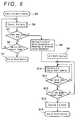
- the shift control is started (S3).
- the solenoid valve So.1 is energized and therefore opened, so that the M2 shift valve 28 is in the position indicated by the left half of its illustration in Fig. 3; and the solenoid valve So.3 is supplied with no electric power and therefor closed, so that the pressure relay valve 27 is in the position indicated by the right half of its illustration; and the solenoid valve So.2 is also supplied with no electric power and therefore closed, so that the U1 shift valve 29 is in the position indicated by the right half of its illustration.
- the line pressure from the D range port 26b of the manual valve 26 is inputted to the input port 20b of the shift pressure control valve 20 through a fluid passage l.
- the shift pressure control valve 20 suitably regulates the pressure and outputs the regulated pressure from the output port 20c.
- the regulated pressure is supplied to the second clutch hydraulic servo C-2 and the C2 accumulator 31, through the ports 27a, 27b of the pressure relay valve 27 and the ports 28a, 28b of the M2 shift valve 28.
- the linear solenoid valve SLS is controlled on the basis of a signal from the electronic control unit U, so that the shift pressure control valve 20 regulates pressure within a range such that the second clutch C2 does not relatively rotate, that is, to a holding pressure P T sufficient to hold the torque.
- a turbine (input) torque is estimated by determining an engine torque from a map based on the throttle opening and the engine speed, and calculating a speed ratio from the input and output rotational speeds of the torque converter, and determining a torque ratio from a map based on the speed ratio, and then multiplying the torque ratio by the engine torque.
- This control step also calculates a target rotational speed changing rate (target rotational acceleration) ⁇ ' of the input shaft targeted when the input shaft speed starts to change.
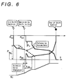
- the releasing-side fluid pressure P C2 is swept down from the target engaging fluid pressure P T set for a period immediately before the input rotational speed starts to change in speed (immediately before the inertia phase) calculated from the aforementioned turbine torque, by a fluid pressure change amount P ⁇ calculated from the target rotational speed changing rate ⁇ '.
- This downsweep is continued until the change in the input shaft speed reaches a shift start determining rotational speed that is detectable by the input shaft speed sensor 35. That is, the shift start is determined at the time point when the fluid pressure amount P ⁇ corresponding to the inertia torque calculated from the target rotational speed changing rate is removed.
- the engine torque that is, input torque
- the torque capacity of the releasing friction engagement elements decreases below the engine torque so that the engine speed starts to increase (the input shaft speed changes), and the input (turbine) rotational speed N T correspondingly starts to increase.
- the 5th-to-4th speed shift operation it is determined whether the target gear speed is the 3rd speed, that is, whether the shift to the 3rd speed has been decided (S5). If the shift to the 3rd speed has not been decided, the 5th-to-4th speed shift operation is continued until the end of shift control (S6). The shift control then ends (S7). More specifically, the torque capacity of the second clutch C2 is gradually reduced. As the second clutch C2 finally becomes released, the first one-way clutch F1 simultaneously becomes engaged. After the fluid pressure on the second clutch hydraulic servo C-2 is drained, the 5th-to-4th speed shift operation ends.
- the control unit immediately turns off the solenoid valve So.1 to close it, and turns on the So.3 to open it, so that the M2 shift valve 28 switches to the position indicated by the right half of its illustration, and the pressure relay valve 27 switches to the position indicated by the left half of its illustration while the U1 shift valve 29 remains in the position indicated by the right half of its illustration (S8).
- the fluid pressure on the second clutch hydraulic servo C-2 and the C2 accumulator 31 is discharged from the port 28b of the M2 shift valve 28 to a drain port through the orifice 30 provided with a check valve.
- the regulated pressure from the output port 20c of the shift pressure control valve 20 is conducted to the third clutch hydraulic servo C-3 through a fluid passage f and the ports 29a, 29b of the U1 shift valve 29.
- the line pressure from the D range port 26b of the manual valve 26 is supplied to the input port 21b of the B-4 control valve 21 through the fluid passage l.
- the B-4 control valve 21 suitably regulates the pressure on the basis of the control pressure from the linear solenoid valve SLT, and outputs the regulated pressure from the output port 21c to the fourth brake hydraulic servo B-4 through the ports 29c, 29d of the U1 shift valve 29.
- the 4th-to-3rd shift control controls an engagement changeover shift of the auxiliary speed shift mechanism 5 where the third clutch C3 is released and the fourth brake B4 is engaged.
- the shift pressure control valve 20 based on the control pressure from the linear solenoid valve SLS, regulates the pressure (P C3 ) to a holding pressure P H that provides the third clutch C3 with a sufficient torque capacity within such a range that the third clutch C3 will not relatively rotate.
- the B-4 control valve 21 based on the control pressure from the linear solenoid valve SLT, performs servo start as indicated by fluid pressure P B4 .
- the fluid pressure on the second clutch hydraulic servo C-2 is smoothly drained through the orifice 30 with a check valve, in accordance with the characteristics of the C2 accumulator 31, which communicates with the second clutch hydraulic servo C-2.
- the main speed shift mechanism 2 will smoothly shift to a 4th-speed state where the second clutch C2 is released.
- the third clutch hydraulic servo C-3 is supplied with the regulated pressure based on the linear solenoid valve SLS, as in the downshift to the 4th speed.
- the pressure on the third clutch hydraulic servo C-3 is regulated by electronic control, independently of the C2 accumulator 31. Therefore, since the C2 accumulator 31 is used only for the release operation during the overlap shift control as described above, the accumulator 31 is allowed to have a less capacity than accumulators normally employed.
- the servo-start control of the fluid pressure P B4 on the fourth brake hydraulic servo B-4, which is to be engaged for the 3rd speed is performed (S10) immediately after a time lag due to the solenoid valve changeover based on the decision to shift to the 3rd speed. More specifically, the fourth brake hydraulic servo B-4 is temporarily supplied with a sufficient fluid pressure to start a piston stroke, and then the fluid pressure P B4 is controlled so that the piston is held at a stroke that is slightly less than the stroke required for torque transmission. This control state is continued for a predetermined time tSA started by the timer (S11).
- the (releasing-side) fluid pressure P C3 on the third clutch hydraulic servo C-3, which is to be released for the 3rd speed, is maintained at a standby level, that is, the predetermined fluid pressure P H that maintains the input torque occurring during the 4th speed.
- the predetermined fluid pressure P H is maintained until the servo-start ends.
- the 4th-to-3rd speed shift control is performed (S13).
- a turbine torque is estimated by correcting the turbine torque value estimated at the start of the 5th-to-4th speed shift, in accordance with the change in the throttle opening. That is, the turbine torque is corrected with an estimated change between the turbine torque at the start of the 5th-to-4th speed shift and the current turbine, and the estimated torque change is determined from a map based on the throttle opening tho at the time of the previous calculation and the current throttle opening thr, as indicated in Fig. 7A.
- the map is pre-arranged, as indicated in Fig.
- a current throttle opening provides an increased turbine torque correction value ⁇ T if the difference ⁇ between the two throttle openings is a positive value (on the right side of the graph of Fig. 7B), that is, if the current throttle opening is greater than the throttle opening at the time of calculation for the 5ht-to-4th speed shift (thr > tho), and such that the same current throttle opening provides a reduced turbine torque correction value ⁇ T if the throttle opening difference ⁇ is a negative value (tho > thr).
- This map arrangement prevents shift shocks in cases where the current throttle opening thr is reduced from the throttle opening tho at the time of the calculation, that is, prevents excessive fluid pressure reductions in such cases, thus preventing the downshift operation from occurring too early, which would cause a shift shock.
- the engine torque is estimated on the basis of a throttle opening change as described above, because it is difficult to directly estimate or detect an actual engine torque in transitional conditions where the engine torque changes, that is, it is difficult to detect an accurate engine speed without a time lag in conditions where the difference between the actual engine torque and the automatic transmission input torque determined by the torque capacity of the friction engagement elements becomes a load that acts on the engine (that is, conditions where the engine is driven by the transmission).
- the turbine torque value corrected from the previous turbine torque value as described above, is then used for calculation of a target fluid pressure value for the releasing-side fluid pressure P C3 , followed by calculation of a target rotational speed changing rate. Then the releasing-side fluid pressure P C3 is accordingly released so that the engaging-side fluid pressure P B5 is increased in accordance with the releasing-side fluid pressure.
- the automatic transmission reaches the inertia phase where a change in the input shaft rotational speed N T occurs (the start of the 4th-to-3rd speed shift)
- the releasing-side fluid pressure P C3 is released with a predetermined gradient based on the rotational speed change while the engaging-side fluid pressure P B4 is increased with a predetermined gradient in accordance with the releasing-side fluid pressure.
- the embodiment may also be applied, in a similar manner, to other overlap shifts, for example, a case where the shift to the 2nd speed is decided on the basis of manual operation of the manual valve 26 to the 2nd range during the 4th-to-5th speed shift.
Landscapes
- Engineering & Computer Science (AREA)
- General Engineering & Computer Science (AREA)
- Physics & Mathematics (AREA)
- Fluid Mechanics (AREA)
- Mechanical Engineering (AREA)
- Control Of Transmission Device (AREA)
Applications Claiming Priority (2)
| Application Number | Priority Date | Filing Date | Title |
|---|---|---|---|
| JP8098957A JPH09287654A (ja) | 1996-04-19 | 1996-04-19 | 自動変速機の制御装置 |
| JP98957/96 | 1996-04-19 |
Publications (2)
| Publication Number | Publication Date |
|---|---|
| EP0802353A2 true EP0802353A2 (fr) | 1997-10-22 |
| EP0802353A3 EP0802353A3 (fr) | 1999-05-19 |
Family
ID=14233573
Family Applications (1)
| Application Number | Title | Priority Date | Filing Date |
|---|---|---|---|
| EP96120387A Ceased EP0802353A3 (fr) | 1996-04-19 | 1996-12-18 | Système de régulation de la pression des embrayages dans une transmission automatique pendant un sauté de vitesse |
Country Status (3)
| Country | Link |
|---|---|
| US (1) | US5924958A (fr) |
| EP (1) | EP0802353A3 (fr) |
| JP (1) | JPH09287654A (fr) |
Cited By (3)
| Publication number | Priority date | Publication date | Assignee | Title |
|---|---|---|---|---|
| EP1249644A2 (fr) | 2001-04-13 | 2002-10-16 | Aisin Aw Co., Ltd. | Dispositif de commande de changement de vitesse pour des transmissions automatiques |
| EP1106873A3 (fr) * | 1999-12-09 | 2004-03-24 | Honda Giken Kogyo Kabushiki Kaisha | Système de commande de transmission automatique de véhicule |
| CN103557298A (zh) * | 2013-10-09 | 2014-02-05 | 山东临工工程机械有限公司 | 基于双涡轮变矩器行星式变速箱的换挡控制装置 |
Families Citing this family (15)
| Publication number | Priority date | Publication date | Assignee | Title |
|---|---|---|---|---|
| US6149548A (en) * | 1999-04-01 | 2000-11-21 | Daimlerchrysler Corporation | Element overlap control for an automatic transmission |
| US6743731B1 (en) * | 2000-11-17 | 2004-06-01 | Agere Systems Inc. | Method for making a radio frequency component and component produced thereby |
| JP3722023B2 (ja) * | 2001-07-27 | 2005-11-30 | トヨタ自動車株式会社 | 車両用自動変速機の変速制御装置 |
| JP3901010B2 (ja) * | 2002-05-17 | 2007-04-04 | アイシン・エィ・ダブリュ株式会社 | 自動変速機の変速制御装置 |
| US7308848B2 (en) * | 2004-12-02 | 2007-12-18 | Sarcos Investments Lc | Pressure control valve having intrinsic feedback system |
| US7284471B2 (en) * | 2004-12-02 | 2007-10-23 | Sarcos Investments Lc | Pressure control valve having intrinsic mechanical feedback system |
| JP4743667B2 (ja) * | 2006-11-06 | 2011-08-10 | 株式会社デンソー | 自動変速機の制御装置 |
| JP5232177B2 (ja) * | 2007-02-28 | 2013-07-10 | レイセオン カンパニー | 作動装置を能動的および受動的に作動させる対立する流体制御システム |
| WO2008106618A1 (fr) * | 2007-02-28 | 2008-09-04 | Raytheon Sarcos, Llc | Système de commande de fluide comprenant des actionneurs utilisables de manière sélective |
| US7779863B2 (en) * | 2007-06-29 | 2010-08-24 | Raytheon Sarcos, Llc | Pressure control valve having an asymmetric valving structure |
| KR100903322B1 (ko) * | 2007-11-02 | 2009-06-16 | 현대자동차주식회사 | 자동변속기의 변속 제어 장치 |
| US8323150B2 (en) * | 2010-05-04 | 2012-12-04 | GM Global Technology Operations LLC | Quick skip-at-sync control system and method |
| DE102011008597A1 (de) * | 2011-01-14 | 2012-07-19 | GM Global Technology Operations LLC (n. d. Ges. d. Staates Delaware) | Verfahren und Mittel zum Steuern des Herunterschaltens |
| US11542883B2 (en) * | 2018-12-07 | 2023-01-03 | Textron Innovations, Inc. | Throttle system |
| CN110886839B (zh) * | 2019-12-11 | 2021-05-28 | 山推工程机械股份有限公司 | 一种推土机换挡控制方法、装置以及计算机存储介质 |
Citations (3)
| Publication number | Priority date | Publication date | Assignee | Title |
|---|---|---|---|---|
| JPH0550621A (ja) | 1991-08-21 | 1993-03-02 | Yokogawa Electric Corp | 熱転写型フルカラー記録装置 |
| JPH0550621B2 (fr) * | 1988-08-05 | 1993-07-29 | Honda Motor Co Ltd | |
| US5285880A (en) * | 1991-05-23 | 1994-02-15 | Nissan Motor Co., Ltd. | Method and apparatus for controlling automatic transmission |
Family Cites Families (10)
| Publication number | Priority date | Publication date | Assignee | Title |
|---|---|---|---|---|
| JPS5865355A (ja) * | 1981-09-29 | 1983-04-19 | Mitsubishi Motors Corp | 自動変速機の油圧制御装置 |
| JPH01283453A (ja) * | 1988-05-09 | 1989-11-15 | Honda Motor Co Ltd | 自動変速機の変速制御方法 |
| US5203234A (en) * | 1989-11-13 | 1993-04-20 | Toyota Jidosha Kabushiki Kaisha | Automatic transmission |
| US5014573A (en) * | 1989-12-11 | 1991-05-14 | General Motors Corporation | Double transition upshift control in an automatic transmission |
| US5439427A (en) * | 1992-04-10 | 1995-08-08 | Mazda Motor Corporation | Multiple stage automatic transmission |
| JPH05306756A (ja) * | 1992-04-30 | 1993-11-19 | Mazda Motor Corp | 自動変速機の制御装置 |
| JPH07119814A (ja) * | 1993-10-25 | 1995-05-12 | Mitsubishi Motors Corp | 自動変速機の変速制御装置 |
| WO1995012774A1 (fr) * | 1993-11-05 | 1995-05-11 | Mitsubishi Jidosha Kogyo Kabushiki Kaisha | Procede de commande de changement de vitesse destine a une transmission automatique |
| DE69519129T2 (de) * | 1994-06-02 | 2001-06-07 | Aisin Aw Co., Ltd. | Steuerungssystem für Automatikgetriebe |
| JP3785672B2 (ja) * | 1996-03-31 | 2006-06-14 | マツダ株式会社 | 自動変速機の制御装置 |
-
1996
- 1996-04-19 JP JP8098957A patent/JPH09287654A/ja active Pending
- 1996-12-18 EP EP96120387A patent/EP0802353A3/fr not_active Ceased
-
1997
- 1997-04-18 US US08/839,824 patent/US5924958A/en not_active Expired - Fee Related
Patent Citations (3)
| Publication number | Priority date | Publication date | Assignee | Title |
|---|---|---|---|---|
| JPH0550621B2 (fr) * | 1988-08-05 | 1993-07-29 | Honda Motor Co Ltd | |
| US5285880A (en) * | 1991-05-23 | 1994-02-15 | Nissan Motor Co., Ltd. | Method and apparatus for controlling automatic transmission |
| JPH0550621A (ja) | 1991-08-21 | 1993-03-02 | Yokogawa Electric Corp | 熱転写型フルカラー記録装置 |
Cited By (5)
| Publication number | Priority date | Publication date | Assignee | Title |
|---|---|---|---|---|
| EP1106873A3 (fr) * | 1999-12-09 | 2004-03-24 | Honda Giken Kogyo Kabushiki Kaisha | Système de commande de transmission automatique de véhicule |
| EP1249644A2 (fr) | 2001-04-13 | 2002-10-16 | Aisin Aw Co., Ltd. | Dispositif de commande de changement de vitesse pour des transmissions automatiques |
| EP1249644A3 (fr) * | 2001-04-13 | 2009-05-06 | Aisin Aw Co., Ltd. | Dispositif de commande de changement de vitesse pour des transmissions automatiques |
| CN103557298A (zh) * | 2013-10-09 | 2014-02-05 | 山东临工工程机械有限公司 | 基于双涡轮变矩器行星式变速箱的换挡控制装置 |
| CN103557298B (zh) * | 2013-10-09 | 2015-12-30 | 山东临工工程机械有限公司 | 基于双涡轮变矩器行星式变速箱的换挡控制装置 |
Also Published As
| Publication number | Publication date |
|---|---|
| JPH09287654A (ja) | 1997-11-04 |
| US5924958A (en) | 1999-07-20 |
| EP0802353A3 (fr) | 1999-05-19 |
Similar Documents
| Publication | Publication Date | Title |
|---|---|---|
| EP0802353A2 (fr) | Système de régulation de la pression des embrayages dans une transmission automatique pendant un sauté de vitesse | |
| JP3339405B2 (ja) | 自動変速機の油圧制御装置 | |
| KR0178323B1 (ko) | 자동변속기의 변속제어장치 | |
| JPH0323784B2 (fr) | ||
| JP2808550B2 (ja) | 自動変速機の制御装置 | |
| JP2813027B2 (ja) | 自動変速機の変速制御装置 | |
| JP3876838B2 (ja) | 車両用高加速時変速制御装置 | |
| US6264580B1 (en) | Control system for automatic transmission | |
| US6962552B2 (en) | Vehicle shift control device and control method therefor | |
| KR970003588B1 (ko) | 자동변속기의 변속제어장치 | |
| JP2002295663A (ja) | 自動変速機の変速制御装置 | |
| US6754572B2 (en) | Hydraulic pressure control apparatus of automatic transmission | |
| JP3688226B2 (ja) | 車両用自動変速機の変速制御装置 | |
| JP3478208B2 (ja) | 自動変速機の油圧制御装置 | |
| US5779585A (en) | Hydraulic control apparatus for automatic transmission | |
| JPH10103494A (ja) | 自動変速機の制御装置 | |
| JPH10213215A (ja) | 自動変速機の変速制御装置 | |
| JPH06109129A (ja) | 自動変速機の制御装置 | |
| JPH10213216A (ja) | 自動変速機の変速制御装置 | |
| JP2008223941A (ja) | 自動変速機 | |
| JP3888021B2 (ja) | 自動変速機のマニュアル変速制御装置 | |
| JP3154758B2 (ja) | 自動変速機の油圧制御装置 | |
| JP3085028B2 (ja) | 自動変速機の変速制御装置 | |
| JP2712909B2 (ja) | 自動変速機の変速制御装置 | |
| JP3994685B2 (ja) | 自動変速機の油圧制御装置 |
Legal Events
| Date | Code | Title | Description |
|---|---|---|---|
| PUAI | Public reference made under article 153(3) epc to a published international application that has entered the european phase |
Free format text: ORIGINAL CODE: 0009012 |
|
| 17P | Request for examination filed |
Effective date: 19970117 |
|
| AK | Designated contracting states |
Kind code of ref document: A2 Designated state(s): DE GB SE |
|
| PUAL | Search report despatched |
Free format text: ORIGINAL CODE: 0009013 |
|
| AK | Designated contracting states |
Kind code of ref document: A3 Designated state(s): DE GB SE |
|
| RTI1 | Title (correction) |
Free format text: APPARATUS TO CONTROL CLUTCH PRESSURE DURING SKIP OR OVERLAP SHIFT OF AN AUTOMATIC TRANSMISSION |
|
| RTI1 | Title (correction) |
Free format text: APPARATUS TO CONTROL CLUTCH PRESSURE DURING SKIP OR OVERLAP SHIFT OF AN AUTOMATIC TRANSMISSION |
|
| RTI1 | Title (correction) |
Free format text: APPARATUS TO CONTROL CLUTCH PRESSURE DURING SKIP OR OVERLAP SHIFT OF AN AUTOMATIC TRANSMISSION |
|
| GRAG | Despatch of communication of intention to grant |
Free format text: ORIGINAL CODE: EPIDOS AGRA |
|
| 17Q | First examination report despatched |
Effective date: 20010213 |
|
| STAA | Information on the status of an ep patent application or granted ep patent |
Free format text: STATUS: THE APPLICATION HAS BEEN REFUSED |
|
| 18R | Application refused |
Effective date: 20010812 |