EP0801996B1 - Verfahren zur Herstellung eines nahtlosen rohrförmigen Stahlprodukts - Google Patents
Verfahren zur Herstellung eines nahtlosen rohrförmigen Stahlprodukts Download PDFInfo
- Publication number
- EP0801996B1 EP0801996B1 EP96106103A EP96106103A EP0801996B1 EP 0801996 B1 EP0801996 B1 EP 0801996B1 EP 96106103 A EP96106103 A EP 96106103A EP 96106103 A EP96106103 A EP 96106103A EP 0801996 B1 EP0801996 B1 EP 0801996B1
- Authority
- EP
- European Patent Office
- Prior art keywords
- plug
- billet
- steel
- piercing
- steel plate
- Prior art date
- Legal status (The legal status is an assumption and is not a legal conclusion. Google has not performed a legal analysis and makes no representation as to the accuracy of the status listed.)
- Expired - Lifetime
Links
Images
Classifications
-
- B—PERFORMING OPERATIONS; TRANSPORTING
- B21—MECHANICAL METAL-WORKING WITHOUT ESSENTIALLY REMOVING MATERIAL; PUNCHING METAL
- B21B—ROLLING OF METAL
- B21B25/00—Mandrels for metal tube rolling mills, e.g. mandrels of the types used in the methods covered by group B21B17/00; Accessories or auxiliary means therefor ; Construction of, or alloys for, mandrels or plugs
- B21B25/04—Cooling or lubricating mandrels during operation
-
- B—PERFORMING OPERATIONS; TRANSPORTING
- B21—MECHANICAL METAL-WORKING WITHOUT ESSENTIALLY REMOVING MATERIAL; PUNCHING METAL
- B21B—ROLLING OF METAL
- B21B19/00—Tube-rolling by rollers arranged outside the work and having their axes not perpendicular to the axis of the work
- B21B19/02—Tube-rolling by rollers arranged outside the work and having their axes not perpendicular to the axis of the work the axes of the rollers being arranged essentially diagonally to the axis of the work, e.g. "cross" tube-rolling ; Diescher mills, Stiefel disc piercers or Stiefel rotary piercers
- B21B19/04—Rolling basic material of solid, i.e. non-hollow, structure; Piercing, e.g. rotary piercing mills
-
- B—PERFORMING OPERATIONS; TRANSPORTING
- B21—MECHANICAL METAL-WORKING WITHOUT ESSENTIALLY REMOVING MATERIAL; PUNCHING METAL
- B21B—ROLLING OF METAL
- B21B17/00—Tube-rolling by rollers of which the axes are arranged essentially perpendicular to the axis of the work, e.g. "axial" tube-rolling
- B21B17/08—Tube-rolling by rollers of which the axes are arranged essentially perpendicular to the axis of the work, e.g. "axial" tube-rolling with mandrel having one or more protrusions, i.e. only the mandrel plugs contact the rolled tube; Press-piercing mills
-
- B—PERFORMING OPERATIONS; TRANSPORTING
- B21—MECHANICAL METAL-WORKING WITHOUT ESSENTIALLY REMOVING MATERIAL; PUNCHING METAL
- B21B—ROLLING OF METAL
- B21B3/00—Rolling materials of special alloys so far as the composition of the alloy requires or permits special rolling methods or sequences ; Rolling of aluminium, copper, zinc or other non-ferrous metals
- B21B3/02—Rolling special iron alloys, e.g. stainless steel
Definitions
- the present invention relates to a method for producing a seamless steel tubular product and, more particularly, to improvement in durability of a piercing plug.
- a seamless steel tubular product is produced as follows.
- a round or square billet is formed into a hollow shell by Mannesmann piercing, press piercing or hot extrusion.
- the hollow shell is rolled by rolling mill such as an elongator, a plug mill and a mandrell mill.
- the rolled hollow shell is formed into a final product having a predetermined size by a sizer and a stretch reducer.
- a plug used for the Mannesmann piercing and press piercing is liable to be damaged since the plug contacts with a billet heated to a high temperature of 1100 to 1300 °C, and since the plug is required to sustain heavy load.
- Piercing plug yet can withstand several hundreds of piercing cycles when used for piercing a billet for low-alloy steel such as carbon steel, but becomes unusable after only several piercing cycles due to heavy damage when used in piercing billets for high-alloy steels represented by 13 Cr steel, SUS 304, SUS 316 and 32 Ni steel. Such an extremely short life of service inevitably leads to a rise in the tool cost.
- lubricant is supplied through the head of the plug via a passage formed in a plug bar which supports the plug.
- This method involves a problem in regard to damaging of the plug end or clogging of the same and, hence, cannot be continuously used in piercing.
- the Prior Art 1 relying upon the use of Mo as the plug material has many advantages such as prevention of deformation of the plug itself, prevention of seizure, and so forth. Mo, however, is expensive and the plug made of this material is rather brittle and tends to be cracked. Thus, the Prior Art 1 also is unsatisfactory when used in industrial scale.
- the hard material is liable to be cracked and the surface-treated layer is easy to peel off. This method therefore has not yet been matured to such a level as to be practically used on actual machines.
- the Prior Art 5 paid attention to oxide scale on the plug surface which is generally understood to have heat-insulating and anti-seizure effects.
- the Prior Art 5 proposes to lower the chromium content as compared with conventionally used plug of 3Cr-lNi steel used for piercing of ordinary steels, and to add at least one selected from molybdenum (Mo), tungsten (W), niobium (Nb), cobalt (Co) and vanadium (V), thereby enabling dense and strong oxide film on the plug surface, while maintaining the strength in high temperature.
- Mo molybdenum
- W tungsten
- Nb niobium
- Co cobalt
- V vanadium
- the life of the alloy steel plug is dependent on the Cr content and the temperature of oxidation treatment, as a result of addition of the above-mentioned elements such as Mo, W, Nb, Co and/or V.
- lowering Cr content and optimization of oxidation treatment can extend the service life of alloy steel plug about 2.5 to 3 times. It is therefore found that the Prior Art 5 can offer extended life of the plug without necessitating any specific limitation or condition.
- the Prior Art 5 however, is still unsatisfactory in that no substantial reduction in the tool cost can be achieved, because the elements added to maintain strength are expensive. Furthermore, considering that initial scale is not produced uniformly and service life of the plug fluctuates is shortened by peel-off of the initial scale, the Prior Art 5 cannot effectively lower the production cost, although it contributes to improvement in efficiency of rolling and working.
- JP-A-1266905 discloses a method for the production of a seamless steel tube according to which the direct contact of the alloy steel of the tube with the piercing plug is avoided. According to this method a common steel plate is joined to the top of the alloy steel to be worked into a seamless tube and then hot piercing is performed by a press piercing process.
- GB 870 750 discloses a process of piercing solid metal ingots with a piercing mandrel, according to which a disc is laid on the ingot through which disc the mandrel has to pierce before entering the ingot.
- the disc is made of a metallic material which is more easily deformable than the material of the ingot itself.
- the piercing process referred to in GB 870750 is a press piercing method.
- JP-A-56-89307 describes a process for the production of seamless steel pipes of sulfur free-cutting steel by a Mannesmann process.
- an ordinary steel chip is welded to the piercing side of the round billet of the sulfur-free cutting steel with 60 degrees X-groove as a blank material.
- After providing this steel-chip with a guide hole in the outer end face piercing is performed by the conventional Mannesmann system. After stretch reduction of the pierced pipe blanc a seamless steel pipe of sulfur free-cutting steel is obtained.
- the present invention provides a method for producing a seamless steel tubular product comprising the steps of :
- the steel plate is made of a carbon steel or a low-alloy steel having a content of elements other than iron lower than that in the alloy steel as the billet material.
- a billet made of alloy steel is firstly prepared.
- a steel plate is joined on an end surface of the billet into which the plug is to be driven so that the steel plate does not extend beyond the outer peripheral surface of the billet.
- the billet with the steel plate is hot-pierced to produce a hollow shell.
- the hollow shell is rolled to obtain a seamless steel tubular product.
- drawbacks of Mannesmann piercing or plug piercing in regard to the plug are difficulty in external supply of a lubricant for preventing seizure and temperature rise, and occurrence of peeling of a lubricant film due to severeness of piercing work, even if the supply of the lubricant is perfomed in a form of the film in advancing of piercing.
- an oxide film which is most widely used at present in actual rolling practice can sustain only several passes or piercing cycles. This is because the heat treatment for forming anti-seizure oxide film is carried out before piercing and such oxide film can be consumed away before long during the piercing.
- the present invention supply of oxide scale from the billet side to the plug is carried out by joining the steel plate on the billet.
- the oxide scale is supplied to form an oxide film each time the piercing is done, in a manner materially equivalent to that performed by heat treatment for forming the film.
- the life of the plug is extended. It is true that the oxide scale is formed on the billet itself.
- the billet alone cannot provide the above-described effect when the alloy steel used as the billet is a high-alloy steel as represented by a stainless steel or a heat-resistant alloy which exhibits much less oxide film formation as compared with carbon steels or low-alloy steels.
- a steel plate is joined to the end surface of the billet into which the piercing plug is to be driven and, if necessary, a similar steel plate is joined also to the other end surface, so that the oxide scale formed by the steel plate is transferred positively to the plug so as to produce lubricating and heat-insulating effects.
- the joining of the steel plate to the billet may be effected by bonding with a suitable adhesive, welding or the like. The joining methods are not necessarily limited to those mentioned.
- a steel plate in the form of a punched blank remains after the piercing on the plug bar which supports the plug.
- a steel composition which otherwise would not exist e.g., carbon steel composition, remains on the inner surface of the pierced high-alloy steel tube.
- ring-shaped steel plate tends to remain on the plug when the size of the joined steel plate is too large, and such residual steel plate is rolled into the hollow shell in the next piercing cycle so as to damage the inner surface of the hollow shell.
- Rolling of the joined steel plate onto the inner surface of the hollow shell in one hand provides good lubrication effect but on the other hand undesirably requires laborious work for finishing the inner surface of the tube in order to meet the requirement for quality of high-alloy steel tubular product.
- the rolling of the steel plate in the hollow shell does not contribute to reduction in the production cost.
- the surface area of the steel plate and, as it may be required, the volume of the steel plate inclusive of the thickness are suitably determined in relation to the sizes of the billet and the plug.
- one of the critical features of the present invention resides in that the plug is prevented from direct contact with the billet of high-alloy steel so as to maintain heat-insulating and lubrication effects on the plug.
- the advantages of the present invention therefore, cannot be enjoyed when the steel plate easy to seize is joined to the billet.
- a steel having a composition which at high temperature produces a compound serving as the major lubrication component such as FeO or a compound of a silicon oxide and Fe.
- ordinary carbon steels, high-silicon steels and low-alloy steels having contents of elements other than Fe lower than those of the billet can suitably be used.
- the method of the present invention features that a steel plate is joined to at least one end surface of the billet into which the plug is to be driven, and the surface area of the steel plate is determined in relation to the sizes of the billet and the plug.
- the steel plate is joined such that the steel plate may not project beyond the peripheral surface of the billet.
- the surface area (C) of the steel plate should satisfy the equation (1): S ⁇ 0.2 ⁇ C ⁇ S ⁇ 1.2 where, S is represented by (plug bottom radius) 2 ⁇ 3.14
- S is represented by (plug bottom radius) 2 ⁇ 3.14
- the steel plate cannot provide any appreciable effect in extending the service life of the plug
- the surface area (C) is over the value of S ⁇ 1.2
- a steel plate having the ring-shaped blank in the punched form remains on the plug bar which supports the plug after the piercing.
- Such remaining steel plate with the ring-shaped blank is rolled into the hollow shell during the piercing of the next billet, which damages the inner surface of the pierced hollow shell.
- the invention also proposes to further define the volume (V) of the steel plate, in order to eliminate troublesome finishing work after piercing while extending the life of service of the plug.
- the volume (V) of the steel plate must satisfy the equation (2): A x 0.1 mm ⁇ V ⁇ A x 5 mm where, A represents the cross-sectional area of the billet.
- the length of the joined steel plate which remains on the inner surface of the hollow shell after the piercing is correlated to the volume (V) of the steel plate.
- V volume of the steel plate.
- the present invention can be well applied to piercing of billets of alloy steels other than the high-alloy steel and billets of non-steel alloys.
- alloys are:
- the present invention it is possible to remarkably extend the service life of a plug used in piercing a billet of a high-alloy steel by a simple measure to joint a steel plate to an end surface of the billet, thus overcoming the problem of too short plug life encountered in the production of a seamless steel tubular product from such high-alloy steel billet which has high additional value but is difficult to roll. Therefore, according to the present invention, it is possible to produce a high-alloys steel seamless tubular product by using exactly the same way as the conventional method and using an alloy steel plug inclusive of conventional plugs, while enjoying remarkably extended life of the plug. Furthermore, the product can be finalized without employing any specific work to be added to the conventional method of finishing. It is thus possible to improve the rolling efficiency and, hence, to reduce the cost of production.
- High-alloy steel billets of 13Cr steel were used.
- a steel plate of an ordinary carbon steel was jointed to the end surface of the billet to which the piercing plug is to be driven (this end surface is referred to as "front end surface") or to the other end surface of the billet (this is referred to as “rear end surface”) or both to the front and rear end surfaces, such that the steel plate or plates may not project beyond the outer periphery of the billet, whereby a plurality of sample billets were prepared.
- the steel plates on different sample billets had different surface areas as shown in Table 1. Sample billets having no such steel plate were also prepared. Each of the sample billets with or without the steel plates was subjected to a process for making seamless steel tubular products.
- the process comprises the steps of hot-piercing a billet by a plug made of a conventional 3Cr-1Ni steel to form a hollow shell and rolling the hollow shell to produce a seamless steel tubular product.
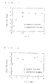
- the durability of service life of the plugs used, as well as the property of the seamless steel tubular product, were examined to obtain results as shown in Table 1 and Fig. 1.
- Table 1 also shows surface areas and thicknesses, as well as data concerning the joint portion, of the sample billets.
- the plug life ratio is expressed in terms of values standarized by the length of plug life as observed when a billet of 13Cr steel having no steel plate joined was pierced.
- the surface area of the steel plate in Table 1 was obtained actually by measuring the surface area of the steel sheet.
- the "plug bottom area" as the value (plug bottom radius) 2 ⁇ 3.14 was actually determined by measuring the projection area of the plug bottom.
- the piercing operation was conducted under the following conditions: Gorge rolling reduction 7 to 15 % Heating temperature 1050 to 1300 °C (varied according to billet steel type) Billet material 13Cr steel Billet diameter 170 ⁇ or 230 ⁇ Piercing plug Conventional plug (made of 3Cr-lNi steel) Material of joined steel plate Ordinary carbon steel
- Comparative Example 3 which largely deviates from the scope of the invention in regard to the steel plate, undesirably allowed part of the steel plate to remain on the plug bar, although it showed substantially the same effect in extending plug service life as Examples of the invention. As a consequence, problems were caused such as damaging of the pipe inner surface, resulting in impairment of the efficiency of work. Comparative Example 3 was therefore evaluated as being not good, which is marked by " ⁇ ".
- Comparative Example 2 which employed a steel plate having a size smaller than that specified by the invention could not show substantial improvement in the plug service life over Comparative Example 1 which did not employ any steel sheet and, hence, was evaluated as being not good as marked by "X ".
- Billets of 32Ni steel were pierced in Example 1 and Comparative Example 6.
- Comparative Example 6 which did not use any steel plate, piercing was impossible, which is marked by " ⁇ "
- Example 12 of the invention which employed a steel plate at least one pass of piercing could be performed, which is marked by " ⁇ ”.
- the range of the volume of the steel plate to be joined which provides appreciable plug life extending effect is broad as seen from Fig. 2. This is attributable to the fact that the volume is a function of both the joining area and the sheet thickness.
- Examples 15 to 18 which satisfy the following requirement, showed excellent results as marked by " ⁇ ", both in the aspects of piercing characteristic and the amount of the steel plate remaining on the pipe inner surface. Namely, these Examples did not cause any trouble in regard to the efficiency of work and the quality of the product.
- Examples 1 to 4 described above employ billets of high-alloy steel, the inventors also have confirmed that advantageous effects similar to those described above are obtainable even when the billets are of low-alloy steels contrasted to the above-mentioned high-alloy steel or of an alloy other than alloy steel, e.g., an Ni-based alloy.
- the present invention offers remarkable advantages from an industrial point of view, by providing a method in which, by a simple measure of joining a steel plate to an end surface of a billet to be pierced.
- the life of the piercing plug is remarkably extended to enable the plug to sustain much greater number of piercing cycles even when the billet is of a high-alloy steel which is generally difficult to pierce.
- the present invention therefore makes it possible to produce seamless steel tubular products of high-alloy steel by a process which is substantially the same as the conventional process, using a piercing plug which also has been used conventionally, thus contributing greatly to improvement in rolling efficiency and reduction in the production cost.
Landscapes
- Engineering & Computer Science (AREA)
- Mechanical Engineering (AREA)
- Pressure Welding/Diffusion-Bonding (AREA)
- Forging (AREA)
Claims (3)
- Verfahren zur Herstellung eines nahtlosen Stahlrohrproduktes, das die Schritte:Herstellen eines Stranges, der aus einem Legierungsstahl besteht, wobei der Strang eine erste und eine zweite Stirnfläche und eine äußere periphere Oberfläche hat; Warmlochen des Stranges durch ein Mannesmann-Lochen unter Verwendung eines Dorns, wobei ein Hohlmantel produziert wird; und Walzen des Hohlmantels umfaßt, dadurch gekennzeichnet, daß es außerdem den folgenden Schritt umfaßt:vor Warmlochen des Stranges Verbinden einer Stahlplatte mit der ersten Stirnfläche des Stranges, in die der Dorn einzutreiben ist, so daß die Stahlplatte nicht über die äußere periphere Oberfläche hinausragt; wobei die Stahlplatte bei der Temperatur des Warmlochens einen Oxidbelag bildet, der zum Schmieren des Dorns während des Warmlochens wirkt; die Stahlplatte eine Oberfläche (C) hat, die die Gleichung (S x 0,2) ≤ C ≤ (S x 1,2), worin S {(Dornbodenradius)2 x 3,14} darstellt, genügt, und ein Volumen (V) hat, das die Bedingung (A x 0,1 mm) ≤ V ≤ (A x 5 mm), worin A die Querschnittsfläche des Stranges darstellt, erfüllt.
- Verfahren nach Anspruch 1, wobei die Stahlplatte eine ist, die aus einem Kohlenstoffstahl hergestellt ist.
- Verfahren nach Anspruch 1, wobei die Stahlplatte eine ist, die aus einem niedrig-legierten Stahl hergestellt ist, der einen niedrigen Gehalt an anderen Elementen als Eisen hat als der Legierungsstahl als das Strangmaterial.
Priority Applications (4)
| Application Number | Priority Date | Filing Date | Title |
|---|---|---|---|
| JP6278460A JP2900804B2 (ja) | 1994-10-18 | 1994-10-18 | プラグ耐用度に優れた継目無鋼管の製造方法 |
| US08/633,169 US5816087A (en) | 1994-10-18 | 1996-04-16 | Method for producing a seamless steel tubular product |
| EP96106103A EP0801996B1 (de) | 1994-10-18 | 1996-04-18 | Verfahren zur Herstellung eines nahtlosen rohrförmigen Stahlprodukts |
| DE1996609159 DE69609159T2 (de) | 1996-04-18 | 1996-04-18 | Verfahren zur Herstellung eines nahtlosen rohrförmigen Stahlprodukts |
Applications Claiming Priority (3)
| Application Number | Priority Date | Filing Date | Title |
|---|---|---|---|
| JP6278460A JP2900804B2 (ja) | 1994-10-18 | 1994-10-18 | プラグ耐用度に優れた継目無鋼管の製造方法 |
| US08/633,169 US5816087A (en) | 1994-10-18 | 1996-04-16 | Method for producing a seamless steel tubular product |
| EP96106103A EP0801996B1 (de) | 1994-10-18 | 1996-04-18 | Verfahren zur Herstellung eines nahtlosen rohrförmigen Stahlprodukts |
Publications (2)
| Publication Number | Publication Date |
|---|---|
| EP0801996A1 EP0801996A1 (de) | 1997-10-22 |
| EP0801996B1 true EP0801996B1 (de) | 2000-07-05 |
Family
ID=27237301
Family Applications (1)
| Application Number | Title | Priority Date | Filing Date |
|---|---|---|---|
| EP96106103A Expired - Lifetime EP0801996B1 (de) | 1994-10-18 | 1996-04-18 | Verfahren zur Herstellung eines nahtlosen rohrförmigen Stahlprodukts |
Country Status (3)
| Country | Link |
|---|---|
| US (1) | US5816087A (de) |
| EP (1) | EP0801996B1 (de) |
| JP (1) | JP2900804B2 (de) |
Families Citing this family (3)
| Publication number | Priority date | Publication date | Assignee | Title |
|---|---|---|---|---|
| US5778714A (en) * | 1995-05-19 | 1998-07-14 | Nkk Corporation | Method for manufacturing seamless pipe |
| GB9919118D0 (en) * | 1999-08-14 | 1999-10-13 | Avecia Ltd | Transfer hydrogenation process |
| RU2386496C2 (ru) * | 2007-08-06 | 2010-04-20 | ОАО "Челябинский трубопрокатный завод" | Способ прокатки труб на установке с автоматическим станом |
Family Cites Families (14)
| Publication number | Priority date | Publication date | Assignee | Title |
|---|---|---|---|---|
| DE1131971B (de) * | 1958-12-03 | 1962-06-20 | Mannesmann Ag | Vorwerkstueck fuer die Herstellung von Rohren aus Vollbloecken |
| US3153482A (en) * | 1963-06-11 | 1964-10-20 | Billie J Buntz | Lubrication of mandrels for tube extrusion |
| US3818733A (en) * | 1972-07-17 | 1974-06-25 | Babcock & Wilcox Co | Piercing process |
| JPS6035205B2 (ja) * | 1979-12-19 | 1985-08-13 | 川崎製鉄株式会社 | いおう快削鋼の継目無鋼管製造方法 |
| US4353238A (en) * | 1981-05-18 | 1982-10-12 | Vallourec, Societe Anonyme | Method for manufacture of seamless metal tubing by continuous rolling |
| JPS6142404A (ja) * | 1984-08-07 | 1986-02-28 | Sumitomo Metal Ind Ltd | 継目無快削鋼鋼管の製造方法 |
| JPS6354066A (ja) * | 1986-08-25 | 1988-03-08 | Nec Corp | 画像符号・復号器 |
| JP2521940B2 (ja) * | 1987-02-05 | 1996-08-07 | 日本鋼管株式会社 | 継目無鋼管製造用プラグ |
| JP2554703B2 (ja) * | 1988-04-18 | 1996-11-13 | 新日本製鐵株式会社 | 管圧延法 |
| JPH02133106A (ja) * | 1988-11-10 | 1990-05-22 | Sumitomo Metal Ind Ltd | 製管機用プラグ |
| JPH02284708A (ja) * | 1989-04-26 | 1990-11-22 | Sumitomo Metal Ind Ltd | 穿孔プラグ |
| JPH03124305A (ja) * | 1989-10-03 | 1991-05-27 | Nippon Steel Corp | 継目無合金鋼管の押込み穿孔圧延方法 |
| JPH048498A (ja) * | 1990-04-20 | 1992-01-13 | Nec Kansai Ltd | シート積層体の切断方法 |
| JPH04274806A (ja) * | 1991-02-27 | 1992-09-30 | Nippon Steel Corp | 継目無合金鋼管の製造方法 |
-
1994
- 1994-10-18 JP JP6278460A patent/JP2900804B2/ja not_active Expired - Fee Related
-
1996
- 1996-04-16 US US08/633,169 patent/US5816087A/en not_active Expired - Lifetime
- 1996-04-18 EP EP96106103A patent/EP0801996B1/de not_active Expired - Lifetime
Also Published As
| Publication number | Publication date |
|---|---|
| JP2900804B2 (ja) | 1999-06-02 |
| JPH08117815A (ja) | 1996-05-14 |
| EP0801996A1 (de) | 1997-10-22 |
| US5816087A (en) | 1998-10-06 |
Similar Documents
| Publication | Publication Date | Title |
|---|---|---|
| EP0743106B1 (de) | Verfahren zur Herstellung eines nahtlosen Rohres | |
| EP1593441B1 (de) | Herstellungsverfahren für ein nahtloses metallrohr | |
| EP1728566B1 (de) | Vorrichtung zur herstellung nahtloser rohre und diese verwendendes verfahren zur herstellung nahtloser rohre | |
| EP0801996B1 (de) | Verfahren zur Herstellung eines nahtlosen rohrförmigen Stahlprodukts | |
| JP2007516351A (ja) | 配管システムに使用されるステンレス鋼管の製造方法 | |
| JPH03204106A (ja) | 熱間継目無管製造用プラグ | |
| JP5075575B2 (ja) | 高温加工用工具 | |
| JPH10137818A (ja) | 継目無鋼管穿孔圧延用プラグ | |
| JPS62207503A (ja) | 高合金鋼継目無管製造用プラグ | |
| JPH05185131A (ja) | 継目無ステンレス鋼管の製造方法 | |
| JP3401118B2 (ja) | シーム疵のない厚鋼板の製造方法 | |
| JP2900795B2 (ja) | プラグ耐用度に優れた高Cr継目無鋼管の製造方法 | |
| JP2911768B2 (ja) | 熱間圧延用ワークロール | |
| JP2864397B2 (ja) | クラッドパイプの製造方法 | |
| JP3085149B2 (ja) | 継目無管製造用穿孔プラグ及び継目無管製造方法 | |
| JPH01289504A (ja) | 鋼管穿孔機用プラグ | |
| JPH10235413A (ja) | 継目無鋼管の製造方法およびビレット穿孔装置 | |
| JPH08309408A (ja) | 穿孔プラグ耐用度に優れた継目無管の製造方法 | |
| JP3274382B2 (ja) | 先端部がテーパーを有する鋼片の圧延方法 | |
| JPH08332504A (ja) | 穿孔プラグ耐用度に優れた継目無管の製造方法 | |
| JP3451990B2 (ja) | 継目無鋼管穿孔圧延用プラグ | |
| JPH0866705A (ja) | 熱間加工用複合被膜形成工具 | |
| JPH0985487A (ja) | 熱間加工用孔型ロール | |
| DE69609159T2 (de) | Verfahren zur Herstellung eines nahtlosen rohrförmigen Stahlprodukts | |
| JP2880991B1 (ja) | 金属長柱体穿孔装置 |
Legal Events
| Date | Code | Title | Description |
|---|---|---|---|
| PUAI | Public reference made under article 153(3) epc to a published international application that has entered the european phase |
Free format text: ORIGINAL CODE: 0009012 |
|
| 17P | Request for examination filed |
Effective date: 19960418 |
|
| AK | Designated contracting states |
Kind code of ref document: A1 Designated state(s): DE FR IT |
|
| 17Q | First examination report despatched |
Effective date: 19980506 |
|
| GRAG | Despatch of communication of intention to grant |
Free format text: ORIGINAL CODE: EPIDOS AGRA |
|
| GRAG | Despatch of communication of intention to grant |
Free format text: ORIGINAL CODE: EPIDOS AGRA |
|
| GRAH | Despatch of communication of intention to grant a patent |
Free format text: ORIGINAL CODE: EPIDOS IGRA |
|
| GRAH | Despatch of communication of intention to grant a patent |
Free format text: ORIGINAL CODE: EPIDOS IGRA |
|
| GRAH | Despatch of communication of intention to grant a patent |
Free format text: ORIGINAL CODE: EPIDOS IGRA |
|
| GRAA | (expected) grant |
Free format text: ORIGINAL CODE: 0009210 |
|
| AK | Designated contracting states |
Kind code of ref document: B1 Designated state(s): DE FR IT |
|
| REF | Corresponds to: |
Ref document number: 69609159 Country of ref document: DE Date of ref document: 20000810 |
|
| ET | Fr: translation filed | ||
| ITF | It: translation for a ep patent filed | ||
| PLBE | No opposition filed within time limit |
Free format text: ORIGINAL CODE: 0009261 |
|
| STAA | Information on the status of an ep patent application or granted ep patent |
Free format text: STATUS: NO OPPOSITION FILED WITHIN TIME LIMIT |
|
| 26N | No opposition filed | ||
| REG | Reference to a national code |
Ref country code: FR Ref legal event code: TP |
|
| REG | Reference to a national code |
Ref country code: FR Ref legal event code: PLFP Year of fee payment: 20 |
|
| PGFP | Annual fee paid to national office [announced via postgrant information from national office to epo] |
Ref country code: DE Payment date: 20150414 Year of fee payment: 20 |
|
| PGFP | Annual fee paid to national office [announced via postgrant information from national office to epo] |
Ref country code: IT Payment date: 20150410 Year of fee payment: 20 Ref country code: FR Payment date: 20150408 Year of fee payment: 20 |
|
| REG | Reference to a national code |
Ref country code: DE Ref legal event code: R071 Ref document number: 69609159 Country of ref document: DE |