EP0794830B1 - Device for mixing particulate material and liquid - Google Patents
Device for mixing particulate material and liquid Download PDFInfo
- Publication number
- EP0794830B1 EP0794830B1 EP95939453A EP95939453A EP0794830B1 EP 0794830 B1 EP0794830 B1 EP 0794830B1 EP 95939453 A EP95939453 A EP 95939453A EP 95939453 A EP95939453 A EP 95939453A EP 0794830 B1 EP0794830 B1 EP 0794830B1
- Authority
- EP
- European Patent Office
- Prior art keywords
- container
- particulate material
- discs
- liquid
- flue gases
- Prior art date
- Legal status (The legal status is an assumption and is not a legal conclusion. Google has not performed a legal analysis and makes no representation as to the accuracy of the status listed.)
- Expired - Lifetime
Links
Images
Classifications
-
- B—PERFORMING OPERATIONS; TRANSPORTING
- B01—PHYSICAL OR CHEMICAL PROCESSES OR APPARATUS IN GENERAL
- B01F—MIXING, e.g. DISSOLVING, EMULSIFYING OR DISPERSING
- B01F23/00—Mixing according to the phases to be mixed, e.g. dispersing or emulsifying
- B01F23/50—Mixing liquids with solids
-
- B—PERFORMING OPERATIONS; TRANSPORTING
- B01—PHYSICAL OR CHEMICAL PROCESSES OR APPARATUS IN GENERAL
- B01F—MIXING, e.g. DISSOLVING, EMULSIFYING OR DISPERSING
- B01F23/00—Mixing according to the phases to be mixed, e.g. dispersing or emulsifying
- B01F23/50—Mixing liquids with solids
- B01F23/54—Mixing liquids with solids wetting solids
-
- B—PERFORMING OPERATIONS; TRANSPORTING
- B01—PHYSICAL OR CHEMICAL PROCESSES OR APPARATUS IN GENERAL
- B01F—MIXING, e.g. DISSOLVING, EMULSIFYING OR DISPERSING
- B01F27/00—Mixers with rotary stirring devices in fixed receptacles; Kneaders
- B01F27/60—Mixers with rotary stirring devices in fixed receptacles; Kneaders with stirrers rotating about a horizontal or inclined axis
- B01F27/73—Mixers with rotary stirring devices in fixed receptacles; Kneaders with stirrers rotating about a horizontal or inclined axis with rotary discs
-
- B—PERFORMING OPERATIONS; TRANSPORTING
- B01—PHYSICAL OR CHEMICAL PROCESSES OR APPARATUS IN GENERAL
- B01F—MIXING, e.g. DISSOLVING, EMULSIFYING OR DISPERSING
- B01F33/00—Other mixers; Mixing plants; Combinations of mixers
- B01F33/40—Mixers using gas or liquid agitation, e.g. with air supply tubes
- B01F33/402—Mixers using gas or liquid agitation, e.g. with air supply tubes comprising supplementary stirring elements
-
- B—PERFORMING OPERATIONS; TRANSPORTING
- B01—PHYSICAL OR CHEMICAL PROCESSES OR APPARATUS IN GENERAL
- B01F—MIXING, e.g. DISSOLVING, EMULSIFYING OR DISPERSING
- B01F33/00—Other mixers; Mixing plants; Combinations of mixers
- B01F33/40—Mixers using gas or liquid agitation, e.g. with air supply tubes
- B01F33/406—Mixers using gas or liquid agitation, e.g. with air supply tubes in receptacles with gas supply only at the bottom
-
- B—PERFORMING OPERATIONS; TRANSPORTING
- B01—PHYSICAL OR CHEMICAL PROCESSES OR APPARATUS IN GENERAL
- B01F—MIXING, e.g. DISSOLVING, EMULSIFYING OR DISPERSING
- B01F23/00—Mixing according to the phases to be mixed, e.g. dispersing or emulsifying
- B01F23/50—Mixing liquids with solids
- B01F23/565—Mixing liquids with solids by introducing liquids in solid material, e.g. to obtain slurries
- B01F23/566—Mixing liquids with solids by introducing liquids in solid material, e.g. to obtain slurries by introducing liquids in a fluidised bed
Definitions
- This invention concerns a device for mixing particulate material and liquid, for instance for mixing water and absorbent material which is reactive with gaseous pollutants in flue gases and which, during cleaning of the flue gases, is to be introduced into these gases in moistened state in order to convert the gaseous pollutants to separable dust, said device comprising a container, an inlet for the introduction of particulate material into the container, a spraying means for spraying liquid over the particulate material in the container, an agitator arranged in the container, and an outlet for discharging material mixed with liquid from the container.
- a mixing device of this kind is revealed in US-PS 4,049,240 for the purpose of moisturizing dry material during removal from a storage bin to avoid dust pollution which could occur during loading and transport.
- a screw conveyor feeds the material to a mixing drum circumscribing the conveyor. Stationary curved blades, inside the rotating drum, direct fine particles into a water shower located within said drum .
- gaseous pollutants such as sulphur dioxide
- the gases are conducted through a contact reactor in which particulate absorbent material reactive with the gaseous pollutants is, in moistened state, introduced into the flue gases in order to convert the gaseous pollutants to separable dust.
- the flue gases are then conducted through a dust separator, in which dust is separated from the flue gases and from which the thus-cleaned flue gases are drawn off.
- Part of the dust separated in the dust separator is conducted to a mixer, where it is mixed and moistened with water, whereupon it is recycled as absorbent material by being introduced into the flue gases along with an addition of fresh absorbent.
- fresh absorbent use is generally made of slaked lime (calcium hydroxide).
- the agitator consists of one or more shafts, on which are mounted agitating means in the form of helical flanges, blades, paddles or the like.
- these prior-art devices are not always capable of producing a homogeneous mixture in which the water is evenly distributed in the particulate material. As a result, moist lumps of material may form, especially when the particulate material contains a large proportion of hydrophobic particles, as is the case with fly ash.
- the absorbent material is supplied to the flue gases in the form of a homogeneous mixture in which the moisture is evenly distributed.
- a special object of this invention is, therefore, to provide a device which is especially adapted to be used for mixing absorbent material and water in the flue-gas-cleaning method described above and which then results in a homogeneous mixture.
- a more general object of the invention is to provide a device which not only results in a homogeneous mixture of particulate material and liquid, but which also has a lower energy consumption than equivalent prior-art devices.
- a device which is of the type mentioned by way of introduction and which is characterised in that the container has an upper bottom and a lower bottom, which between them define a chamber and of which the upper bottom is air-permeable, and there is provided an air-supply means adapted to supply air to the chamber with a view to fluidising the particulate material in the container.
- the agitator consists of at least one rotary shaft which extends along the container and on which a plurality of discs, through the centres of which extends the shaft, are mounted in inclined state at an axial distance from one another .
- these discs have an elliptic shape and are, about their minor axes, so inclined in relation to the shaft as to have a circular axial projection.
- the discs are inclined at an angle of 45-80°, preferably about 60° .
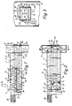
- the mixing device illustrated comprises a container 1, which essentially is in the shape of an elongate, parallelepidal box.
- the container 1 has vertical side walls 2 and 3, a vertical rear end wall 4, a vertical front end wall 5, a horizontal upper bottom 6, a horizontal lower bottom 7 and a horizontal top or lid 8.
- the container 1 has an inlet 9, through which particulate material is supplied from above (the arrow P1 in Fig. 1).
- the container 1 has an outlet 10, through which is discharged a homogeneous mixture of particulate material and water (the arrows P2 in Figs 2 and 3).
- the front end of the container 1 is inserted in a vertical flue-gas channel 11 through which flue gases containing gaseous pollutants, such as sulphur dioxide, are conducted upwards (the arrows P3 in Figs 1 and 3) in order to be cleaned in known fashion.
- the outlet 10 is an overflow formed as a result of the side walls 2 and 3 being lower in the container part inserted in the channel 11 than in the container part located outside the channel 11.
- the top 8 extends from the inlet 9 to the outlet 10, i.e. up to the flue-gas channel 11.
- the two bottoms 6 and 7 define a chamber 12 which, in the lateral direction, is delimited by the two side walls 2 and 3 and, in the longitudinal direction, is delimited by the two end walls 4 and 5.
- the ceiling of the chamber 12, i.e. the upper bottom 6, consists of an air-permeable fluidisation cloth of polyester mounted in stretched state in the container 1.
- An air-supply means, which here consists of two air inlets 13 and 14, is arranged to supply air to the chamber 12 (the arrows P4 in Figs 1 and 2), so as to fluidise the particulate material in the container 1.
- Two juxtaposed, horizontal shafts 17, 17' extend along the entire container 1 and are rotatably mounted in the two end walls 4 and 5 with the aid of bearings 18, 18' and 19, 19', respectively.
- a motor 20 is arranged to rotate the shafts 17, 17' via a transmission unit 21.
- Each shaft 17, 17' supports a plurality of elliptic discs 22, 22' which, about their minor axes, are mounted in inclined state on the shaft 17, 17' at an axial distance from one another.
- the shafts 17, 17' extend through the centres of the respective discs 22, 22'.
- each disc 22, 22' is so inclined in relation to the shaft 17, 17' that the angle ⁇ between the major axis of the disc and the shaft 17, 17' is about 60° (see Fig. 1). This angle ⁇ may vary between 45° and 80°.
- the discs 22, 22' are so inclined in relation to the respective shafts 17, 17' and have such an elliptic shape as to have a circular axial projection, as illustrated in Fig. 3.
- the discs 22, 22' are so positioned on the respective shafts 17, 17' that the discs of the one shaft project into the spaces between the discs of the other shaft.
- Each of the discs 22, 22' arranged and designed in the manner indicated above performs, during the rotation of the shafts 17, 17', a throwing movement conducive to thorough mixing of particulate material.
- the flue-gas channel 11 illustrated forms part of a system for cleaning flue gases containing gaseous pollutants, such as sulphur dioxide.
- the flue gases (P3) are passed through the flue-gas channel 11, in which particulate absorbent material reactive with the gaseous pollutants is, in moistened state, introduced into the flue gases in order to convert the gaseous pollutants to separable dust.
- the flue gases are then passed through a dust separator (not shown), in which dust is separated from the flue gases and from which the thus-cleaned flue gases are discharged into the surrounding atmosphere. Part of the dust separated in the dust separator is, along with an addition of fresh absorbent, e.g.
- particulate material (P1) supplied as particulate material (P1) to the inlet 9 of the container 1, so as to be, in the container, mixed with water sprayed over the particulate material in the container through the nozzles 16.
- P4 The particulate material in the container 1 is maintained in fluidised state by means of air (P4) which, via the air inlets 13 and 14, the chamber 12 and the fluidisation cloth 6, is introduced into the container.
- the chamber 12 is divided into a front part chamber 12a, which is situated in the flue-gas channel 11, and a rear part chamber 12b.
- the air inlet 13 opens into the rear part chamber 12b, while the air inlet 14 opens into the front part chamber 12a.
- the container 1 was filled with particulate material.
- the container 1 had a volume of 0.3 m 3 .
- the shafts 17, 17' were rotated at a speed of 200 rpm.
- the flow rate of particulate material passing through the container was 8 m 3 /h, and the flow rate of the water was 240 1/h.
- the power consumption including the power consumption of the supply of fluidisation air (0.08 m 3 /s), was found to be 2.2 kW. With no fluidisation but otherwise under the same conditions, the power consumption was 3 kW.
- the mixing device may also be used for discharging a homogeneously moistened, homogeneous mixture of particulate material into two separate channels, in which case the front end of the container 1 extends into these two channels in such a manner that the mixture is discharged into the one channel via the overflow 10 in the side wall 2 and discharged into the other channel via the overflow 10 in the side wall 3.
- the relationship between the flows of material to the two channels may be set by choosing suitable levels for the overflow 10 at the respective sides, i.e. by a suitable choice of height for the respective side walls 2, 3 in the container part inserted in the channels.
Landscapes
- Chemical & Material Sciences (AREA)
- Chemical Kinetics & Catalysis (AREA)
- Dispersion Chemistry (AREA)
- Treating Waste Gases (AREA)
- Nozzles (AREA)
- Hydrogen, Water And Hydrids (AREA)
- Devices And Processes Conducted In The Presence Of Fluids And Solid Particles (AREA)
- Package Specialized In Special Use (AREA)
- Unwinding Webs (AREA)
- Paints Or Removers (AREA)
- Mixers Of The Rotary Stirring Type (AREA)
Applications Claiming Priority (3)
| Application Number | Priority Date | Filing Date | Title |
|---|---|---|---|
| SE9404104 | 1994-11-28 | ||
| SE9404104A SE503674C2 (sv) | 1994-11-28 | 1994-11-28 | Anordning för blandning av partikelformigt material och vätska |
| PCT/SE1995/001401 WO1996016727A1 (en) | 1994-11-28 | 1995-11-24 | Device for mixing particulate material and liquid |
Publications (2)
| Publication Number | Publication Date |
|---|---|
| EP0794830A1 EP0794830A1 (en) | 1997-09-17 |
| EP0794830B1 true EP0794830B1 (en) | 2002-02-06 |
Family
ID=20396124
Family Applications (1)
| Application Number | Title | Priority Date | Filing Date |
|---|---|---|---|
| EP95939453A Expired - Lifetime EP0794830B1 (en) | 1994-11-28 | 1995-11-24 | Device for mixing particulate material and liquid |
Country Status (28)
| Country | Link |
|---|---|
| US (1) | US5887973A (sv) |
| EP (1) | EP0794830B1 (sv) |
| JP (1) | JP3649290B2 (sv) |
| KR (1) | KR100425997B1 (sv) |
| CN (1) | CN1076980C (sv) |
| AT (1) | ATE212875T1 (sv) |
| AU (1) | AU699500B2 (sv) |
| BR (1) | BR9509828A (sv) |
| CA (1) | CA2205059C (sv) |
| CZ (1) | CZ287812B6 (sv) |
| DE (1) | DE69525370T2 (sv) |
| DK (1) | DK0794830T3 (sv) |
| EE (1) | EE9700119A (sv) |
| ES (1) | ES2172602T3 (sv) |
| FI (1) | FI972232A (sv) |
| HU (1) | HU221802B1 (sv) |
| MD (1) | MD1228G2 (sv) |
| PL (1) | PL178051B1 (sv) |
| PT (1) | PT794830E (sv) |
| RO (1) | RO115424B1 (sv) |
| RU (1) | RU2137535C1 (sv) |
| SE (1) | SE503674C2 (sv) |
| SI (1) | SI9520142B (sv) |
| SK (1) | SK282040B6 (sv) |
| TR (1) | TR199501493A1 (sv) |
| UA (1) | UA32603C2 (sv) |
| WO (1) | WO1996016727A1 (sv) |
| ZA (1) | ZA959875B (sv) |
Families Citing this family (28)
| Publication number | Priority date | Publication date | Assignee | Title |
|---|---|---|---|---|
| SE508868C2 (sv) * | 1997-03-17 | 1998-11-09 | Flaekt Ab | Anordning för blandning av partikelformigt material och vätska |
| US6685886B2 (en) * | 1998-12-17 | 2004-02-03 | Genencor International, Inc. | Agitation system for a fluid bed processing system and a method thereof |
| SE523667C2 (sv) * | 2002-09-20 | 2004-05-11 | Alstom Switzerland Ltd | Förfarande och anordning för avskiljning av gasformiga föroreningar från varma gaser medelst partikelformigt absorbentmaterial samt blandare för befuktning av absorbentmaterialet |
| US20040085856A1 (en) * | 2002-10-30 | 2004-05-06 | Murosako James K. | Mixer |
| GB0322358D0 (en) * | 2003-09-24 | 2003-10-22 | Bioprogress Technology Ltd | Improvements in powder compaction and enrobing |
| AT504426B8 (de) * | 2006-10-24 | 2008-09-15 | Scheuch Gmbh | Vorrichtung zum befeuchten eines sorptionsmittels |
| ITTO20070084A1 (it) * | 2007-02-06 | 2008-08-07 | K & E Srl | Dispositivi di miscelazione radiale per reattori inclinati rotanti. |
| DE102007057401A1 (de) * | 2007-11-27 | 2009-05-28 | Friedrich Hellmich | Verfahren zur Aufbereitung von Sorptionsmaterial bei der Rauchgasreinigung in Ziegeleien |
| EP2990094A1 (en) | 2010-11-24 | 2016-03-02 | Alstom Technology Ltd | Method of cleaning a carbon dioxide rich flue gas and a boiler system |
| US10343098B2 (en) | 2013-05-13 | 2019-07-09 | General Electric Company | Cleaning valve with dampening mechanism |
| US9993762B2 (en) | 2013-05-13 | 2018-06-12 | General Electric Technology Gmbh | Quiet pulse valve |
| CN103239958A (zh) * | 2013-05-27 | 2013-08-14 | 芜湖华洁环保设备有限公司 | 加湿机 |
| US9108152B2 (en) | 2013-11-26 | 2015-08-18 | Alstom Technology Ltd | Dry scrubber system with low load distributor device |
| US8906333B1 (en) | 2013-11-27 | 2014-12-09 | Alstom Technology Ltd | Dry scrubber system with air preheater protection |
| US9084964B1 (en) | 2014-05-08 | 2015-07-21 | Alstom Technology | Radial fabric filter for particulate collection |
| CN104069770A (zh) * | 2014-06-30 | 2014-10-01 | 张家港市锦明机械有限公司 | 一种新型整体脱硫混合器 |
| US10092872B2 (en) | 2014-09-17 | 2018-10-09 | General Electric Technology Gmbh | Valve with small vessel penetration diameter |
| DK3002051T3 (da) | 2014-10-03 | 2020-03-30 | General Electric Technology Gmbh | Støvseparator, som er nyttig med tørskrubbersystem |
| US20160175793A1 (en) * | 2014-12-18 | 2016-06-23 | General Electric Company | Material transporting devices and systems |
| EP3269692A1 (en) * | 2016-07-11 | 2018-01-17 | General Electric Technology GmbH | Integrated lime hydrator |
| CN106000159A (zh) * | 2016-07-15 | 2016-10-12 | 智胜化工股份有限公司 | 一种粉灰加湿机水分布器装置 |
| US10232310B2 (en) | 2016-10-05 | 2019-03-19 | General Electric Technology Gmbh | Multi-function duct for dry scrubber system |
| US11092980B2 (en) | 2016-11-16 | 2021-08-17 | General Electric Technology Gmbh | Pulse valve with pressure vessel penetration |
| EP3323496B1 (en) | 2016-11-18 | 2020-09-16 | General Electric Technology GmbH | Apparatus and method for reducing acid gas emissions with zero liquid discharge of waste water |
| PL3403709T3 (pl) | 2017-05-19 | 2020-08-10 | General Electric Technology Gmbh | Filtr tkaninowy przeciw emisji niskiej zawartości cząstek stałych |
| CN111468026B (zh) * | 2020-04-13 | 2022-04-12 | 中冶长天国际工程有限责任公司 | 一种物料加湿控制系统及控制方法 |
| US11890782B2 (en) * | 2020-06-05 | 2024-02-06 | Vermeer Manufacturing Company | Mixing systems having disk assemblies |
| US11439947B2 (en) | 2020-08-28 | 2022-09-13 | Andritz Aktiebolag | System and method for mixing recirculating combustion ash with hydrated lime and water |
Family Cites Families (14)
| Publication number | Priority date | Publication date | Assignee | Title |
|---|---|---|---|---|
| US1247153A (en) * | 1914-11-04 | 1917-11-20 | Sherman C Roberts | Apparatus for producing animal-fodder. |
| US1420008A (en) * | 1920-09-25 | 1922-06-20 | Henry S Wikel | Apparatus for preparing stock food |
| DE409844C (de) * | 1922-06-20 | 1925-02-12 | Farbenfab Vorm Bayer F & Co | Vorrichtung zur Herbeifuehrung einer innigen Mischung zwischen Gasen und Fluessigkeiten |
| US2320469A (en) * | 1940-06-24 | 1943-06-01 | Smidth & Co As F L | Mixing and homogenizing apparatus |
| GB710306A (en) * | 1951-12-21 | 1954-06-09 | Amalgamated Limestone Corp Ltd | Improvements relating to the mixing and conveying of powdered materials |
| US2946574A (en) * | 1957-08-30 | 1960-07-26 | Wibau Gmbh | Installation for making briquettes |
| US3202281A (en) * | 1964-10-01 | 1965-08-24 | Weston David | Method for the flotation of finely divided minerals |
| FR1412119A (fr) * | 1964-10-19 | 1965-09-24 | Dispositif pour la dispersion de particules solides en suspension de façon à les amener à l'état de finesse colloïdale | |
| US3343814A (en) * | 1965-06-01 | 1967-09-26 | Bahre Metallwerk K G Fa | Device for coating chips with glue |
| USRE29387E (en) * | 1971-08-26 | 1977-09-06 | Pettibone Corporation | Apparatus for the continuous mixing of granular materials |
| US3997689A (en) * | 1975-07-17 | 1976-12-14 | Uop Inc. | Preparation of semiconducting pyropolymeric inorganic refractory oxide materials |
| DE2602454B2 (de) * | 1976-01-23 | 1980-12-11 | Claudius Peters Ag, 2000 Hamburg | Vorrichtung zum Behandeln pulvriger oder körniger Stoffe mit einer Flüssigkeit |
| US4049240A (en) * | 1976-06-16 | 1977-09-20 | Ecolaire Incorporated | Continuous mixer and unloader |
| US4306815A (en) * | 1979-07-12 | 1981-12-22 | Urad Predsednictva Slovenskej Akademie Ved | Apparatus for processing materials which are difficult to expand with gas and/or liquid, in an expanded layer |
-
1994
- 1994-11-28 SE SE9404104A patent/SE503674C2/sv not_active IP Right Cessation
-
1995
- 1995-11-21 ZA ZA959875A patent/ZA959875B/xx unknown
- 1995-11-24 RO RO97-00950A patent/RO115424B1/ro unknown
- 1995-11-24 DE DE69525370T patent/DE69525370T2/de not_active Expired - Fee Related
- 1995-11-24 HU HU9800495A patent/HU221802B1/hu not_active IP Right Cessation
- 1995-11-24 JP JP51716896A patent/JP3649290B2/ja not_active Expired - Lifetime
- 1995-11-24 CA CA002205059A patent/CA2205059C/en not_active Expired - Fee Related
- 1995-11-24 PT PT95939453T patent/PT794830E/pt unknown
- 1995-11-24 AT AT95939453T patent/ATE212875T1/de not_active IP Right Cessation
- 1995-11-24 RU RU97110654A patent/RU2137535C1/ru not_active IP Right Cessation
- 1995-11-24 KR KR1019970703615A patent/KR100425997B1/ko not_active IP Right Cessation
- 1995-11-24 SK SK660-97A patent/SK282040B6/sk unknown
- 1995-11-24 PL PL95320348A patent/PL178051B1/pl not_active IP Right Cessation
- 1995-11-24 BR BR9509828A patent/BR9509828A/pt not_active IP Right Cessation
- 1995-11-24 US US08/849,113 patent/US5887973A/en not_active Expired - Lifetime
- 1995-11-24 AU AU41262/96A patent/AU699500B2/en not_active Ceased
- 1995-11-24 CN CN95196446A patent/CN1076980C/zh not_active Expired - Lifetime
- 1995-11-24 UA UA97063093A patent/UA32603C2/uk unknown
- 1995-11-24 SI SI9520142A patent/SI9520142B/sl not_active IP Right Cessation
- 1995-11-24 ES ES95939453T patent/ES2172602T3/es not_active Expired - Lifetime
- 1995-11-24 DK DK95939453T patent/DK0794830T3/da active
- 1995-11-24 EE EE9700119A patent/EE9700119A/xx unknown
- 1995-11-24 CZ CZ19971573A patent/CZ287812B6/cs not_active IP Right Cessation
- 1995-11-24 EP EP95939453A patent/EP0794830B1/en not_active Expired - Lifetime
- 1995-11-24 WO PCT/SE1995/001401 patent/WO1996016727A1/en active IP Right Grant
- 1995-11-24 MD MD97-0234A patent/MD1228G2/ro unknown
- 1995-11-27 TR TR95/01493A patent/TR199501493A1/xx unknown
-
1997
- 1997-05-27 FI FI972232A patent/FI972232A/sv not_active IP Right Cessation
Also Published As
Similar Documents
| Publication | Publication Date | Title |
|---|---|---|
| EP0794830B1 (en) | Device for mixing particulate material and liquid | |
| EP1009523B1 (en) | Device for mixing particulate material and liquid | |
| RU97110654A (ru) | Устройство для смешивания частиц вещества с жидкостью | |
| EP0891219A1 (en) | Device for discharging and distributing an absorbent material in a flue gas duct | |
| EP0876191B1 (en) | Method for separating dust from hot process gases | |
| CN201572600U (zh) | 一种垃圾焚烧烟气净化干法脱酸系统 | |
| US3991480A (en) | Method of and apparatus for the drying of odoriferous organic substances | |
| US4584179A (en) | Apparatus for treating cement kiln dust | |
| CA2033372C (en) | S02 control using moving granular beds | |
| CZ325499A3 (cs) | Zařízení pro směšování částicovitého materiálu a kapaliny |
Legal Events
| Date | Code | Title | Description |
|---|---|---|---|
| PUAI | Public reference made under article 153(3) epc to a published international application that has entered the european phase |
Free format text: ORIGINAL CODE: 0009012 |
|
| 17P | Request for examination filed |
Effective date: 19970602 |
|
| AK | Designated contracting states |
Kind code of ref document: A1 Designated state(s): AT BE CH DE DK ES FR GB GR IE IT LI NL PT |
|
| AX | Request for extension of the european patent |
Free format text: LT PAYMENT 970602;LV PAYMENT 970602 |
|
| 17Q | First examination report despatched |
Effective date: 19991020 |
|
| GRAG | Despatch of communication of intention to grant |
Free format text: ORIGINAL CODE: EPIDOS AGRA |
|
| GRAG | Despatch of communication of intention to grant |
Free format text: ORIGINAL CODE: EPIDOS AGRA |
|
| GRAH | Despatch of communication of intention to grant a patent |
Free format text: ORIGINAL CODE: EPIDOS IGRA |
|
| GRAH | Despatch of communication of intention to grant a patent |
Free format text: ORIGINAL CODE: EPIDOS IGRA |
|
| GRAA | (expected) grant |
Free format text: ORIGINAL CODE: 0009210 |
|
| REG | Reference to a national code |
Ref country code: GB Ref legal event code: IF02 |
|
| AK | Designated contracting states |
Kind code of ref document: B1 Designated state(s): AT BE CH DE DK ES FR GB GR IE IT LI NL PT |
|
| AX | Request for extension of the european patent |
Free format text: LT PAYMENT 19970602;LV PAYMENT 19970602 |
|
| REF | Corresponds to: |
Ref document number: 212875 Country of ref document: AT Date of ref document: 20020215 Kind code of ref document: T |
|
| REG | Reference to a national code |
Ref country code: CH Ref legal event code: EP |
|
| REF | Corresponds to: |
Ref document number: 69525370 Country of ref document: DE Date of ref document: 20020321 |
|
| REG | Reference to a national code |
Ref country code: DK Ref legal event code: T3 |
|
| RAP2 | Party data changed (patent owner data changed or rights of a patent transferred) |
Owner name: ALSTOM POWER SWEDEN HOLDING AB |
|
| REG | Reference to a national code |
Ref country code: CH Ref legal event code: NV Representative=s name: PATENTANWAELTE FELDMANN & PARTNER AG |
|
| REG | Reference to a national code |
Ref country code: GB Ref legal event code: 732E |
|
| REG | Reference to a national code |
Ref country code: PT Ref legal event code: SC4A Free format text: AVAILABILITY OF NATIONAL TRANSLATION Effective date: 20020423 Ref country code: PT Ref legal event code: PC4A Free format text: ALSTOM POWER SWEDEN HOLDING AB SE Effective date: 20020503 |
|
| NLT2 | Nl: modifications (of names), taken from the european patent patent bulletin |
Owner name: ALSTOM POWER SWEDEN HOLDING AB |
|
| ET | Fr: translation filed | ||
| REG | Reference to a national code |
Ref country code: GR Ref legal event code: EP Ref document number: 20020401546 Country of ref document: GR |
|
| REG | Reference to a national code |
Ref country code: ES Ref legal event code: FG2A Ref document number: 2172602 Country of ref document: ES Kind code of ref document: T3 |
|
| REG | Reference to a national code |
Ref country code: FR Ref legal event code: TP |
|
| NLS | Nl: assignments of ep-patents |
Owner name: ALSTOM POWER SWEDEN HOLDING AB |
|
| PLBE | No opposition filed within time limit |
Free format text: ORIGINAL CODE: 0009261 |
|
| STAA | Information on the status of an ep patent application or granted ep patent |
Free format text: STATUS: NO OPPOSITION FILED WITHIN TIME LIMIT |
|
| BECA | Be: change of holder's address |
Free format text: 20020206 *ALSTOM POWER SWEDEN HOLDING AB:612 82 FINSPANG |
|
| BECH | Be: change of holder |
Free format text: 20020206 *ALSTOM POWER SWEDEN HOLDING AB |
|
| 26N | No opposition filed |
Effective date: 20021107 |
|
| PGFP | Annual fee paid to national office [announced via postgrant information from national office to epo] |
Ref country code: GR Payment date: 20040928 Year of fee payment: 10 |
|
| PGFP | Annual fee paid to national office [announced via postgrant information from national office to epo] |
Ref country code: NL Payment date: 20041103 Year of fee payment: 10 |
|
| PGFP | Annual fee paid to national office [announced via postgrant information from national office to epo] |
Ref country code: IE Payment date: 20041111 Year of fee payment: 10 Ref country code: AT Payment date: 20041111 Year of fee payment: 10 |
|
| PGFP | Annual fee paid to national office [announced via postgrant information from national office to epo] |
Ref country code: DK Payment date: 20041116 Year of fee payment: 10 |
|
| PGFP | Annual fee paid to national office [announced via postgrant information from national office to epo] |
Ref country code: PT Payment date: 20041118 Year of fee payment: 10 Ref country code: DE Payment date: 20041118 Year of fee payment: 10 |
|
| PGFP | Annual fee paid to national office [announced via postgrant information from national office to epo] |
Ref country code: CH Payment date: 20041129 Year of fee payment: 10 |
|
| PGFP | Annual fee paid to national office [announced via postgrant information from national office to epo] |
Ref country code: ES Payment date: 20041214 Year of fee payment: 10 |
|
| PGFP | Annual fee paid to national office [announced via postgrant information from national office to epo] |
Ref country code: BE Payment date: 20050215 Year of fee payment: 10 |
|
| PG25 | Lapsed in a contracting state [announced via postgrant information from national office to epo] |
Ref country code: IE Free format text: LAPSE BECAUSE OF NON-PAYMENT OF DUE FEES Effective date: 20051124 Ref country code: AT Free format text: LAPSE BECAUSE OF NON-PAYMENT OF DUE FEES Effective date: 20051124 |
|
| PG25 | Lapsed in a contracting state [announced via postgrant information from national office to epo] |
Ref country code: ES Free format text: LAPSE BECAUSE OF NON-PAYMENT OF DUE FEES Effective date: 20051125 |
|
| PG25 | Lapsed in a contracting state [announced via postgrant information from national office to epo] |
Ref country code: LI Free format text: LAPSE BECAUSE OF NON-PAYMENT OF DUE FEES Effective date: 20051130 Ref country code: DK Free format text: LAPSE BECAUSE OF NON-PAYMENT OF DUE FEES Effective date: 20051130 Ref country code: CH Free format text: LAPSE BECAUSE OF NON-PAYMENT OF DUE FEES Effective date: 20051130 Ref country code: BE Free format text: LAPSE BECAUSE OF NON-PAYMENT OF DUE FEES Effective date: 20051130 |
|
| PG25 | Lapsed in a contracting state [announced via postgrant information from national office to epo] |
Ref country code: PT Free format text: LAPSE BECAUSE OF NON-PAYMENT OF DUE FEES Effective date: 20060524 |
|
| PG25 | Lapsed in a contracting state [announced via postgrant information from national office to epo] |
Ref country code: NL Free format text: LAPSE BECAUSE OF NON-PAYMENT OF DUE FEES Effective date: 20060601 Ref country code: DE Free format text: LAPSE BECAUSE OF NON-PAYMENT OF DUE FEES Effective date: 20060601 |
|
| REG | Reference to a national code |
Ref country code: DK Ref legal event code: EBP |
|
| REG | Reference to a national code |
Ref country code: CH Ref legal event code: PL |
|
| REG | Reference to a national code |
Ref country code: PT Ref legal event code: MM4A Effective date: 20060524 |
|
| NLV4 | Nl: lapsed or anulled due to non-payment of the annual fee |
Effective date: 20060601 |
|
| REG | Reference to a national code |
Ref country code: IE Ref legal event code: MM4A |
|
| REG | Reference to a national code |
Ref country code: ES Ref legal event code: FD2A Effective date: 20051125 |
|
| BERE | Be: lapsed |
Owner name: *ALSTOM POWER SWEDEN HOLDING AB Effective date: 20051130 |
|
| REG | Reference to a national code |
Ref country code: FR Ref legal event code: CD |
|
| PG25 | Lapsed in a contracting state [announced via postgrant information from national office to epo] |
Ref country code: GR Free format text: LAPSE BECAUSE OF NON-PAYMENT OF DUE FEES Effective date: 20020206 |
|
| REG | Reference to a national code |
Ref country code: FR Ref legal event code: TP Owner name: ALSTOM TECHNOLOGY LTD., CH Effective date: 20130213 |
|
| REG | Reference to a national code |
Ref country code: GB Ref legal event code: 732E Free format text: REGISTERED BETWEEN 20130418 AND 20130424 |
|
| PGFP | Annual fee paid to national office [announced via postgrant information from national office to epo] |
Ref country code: FR Payment date: 20141119 Year of fee payment: 20 Ref country code: GB Payment date: 20141119 Year of fee payment: 20 |
|
| PGFP | Annual fee paid to national office [announced via postgrant information from national office to epo] |
Ref country code: IT Payment date: 20141125 Year of fee payment: 20 |
|
| REG | Reference to a national code |
Ref country code: GB Ref legal event code: PE20 Expiry date: 20151123 |
|
| PG25 | Lapsed in a contracting state [announced via postgrant information from national office to epo] |
Ref country code: GB Free format text: LAPSE BECAUSE OF EXPIRATION OF PROTECTION Effective date: 20151123 |