EP0787460A2 - Anschlussstück eines Filterbeutels für Staubsauger - Google Patents
Anschlussstück eines Filterbeutels für Staubsauger Download PDFInfo
- Publication number
- EP0787460A2 EP0787460A2 EP96120553A EP96120553A EP0787460A2 EP 0787460 A2 EP0787460 A2 EP 0787460A2 EP 96120553 A EP96120553 A EP 96120553A EP 96120553 A EP96120553 A EP 96120553A EP 0787460 A2 EP0787460 A2 EP 0787460A2
- Authority
- EP
- European Patent Office
- Prior art keywords
- material layer
- base body
- perforation
- ring
- slide
- Prior art date
- Legal status (The legal status is an assumption and is not a legal conclusion. Google has not performed a legal analysis and makes no representation as to the accuracy of the status listed.)
- Granted
Links
Images

Classifications
-
- A—HUMAN NECESSITIES
- A47—FURNITURE; DOMESTIC ARTICLES OR APPLIANCES; COFFEE MILLS; SPICE MILLS; SUCTION CLEANERS IN GENERAL
- A47L—DOMESTIC WASHING OR CLEANING; SUCTION CLEANERS IN GENERAL
- A47L9/00—Details or accessories of suction cleaners, e.g. mechanical means for controlling the suction or for effecting pulsating action; Storing devices specially adapted to suction cleaners or parts thereof; Carrying-vehicles specially adapted for suction cleaners
- A47L9/10—Filters; Dust separators; Dust removal; Automatic exchange of filters
- A47L9/14—Bags or the like; Rigid filtering receptacles; Attachment of, or closures for, bags or receptacles
- A47L9/1427—Means for mounting or attaching bags or filtering receptacles in suction cleaners; Adapters
- A47L9/1436—Connecting plates, e.g. collars, end closures
- A47L9/1445—Connecting plates, e.g. collars, end closures with closure means
Definitions
- the invention relates to a connection piece of a filter bag for vacuum cleaners, with a fixed, substantially plate-shaped base body, which has an inner material layer facing the bag and an outer material layer facing away from the bag, these material layers, in particular made of cardboard material, which are arranged one above the other and one between them
- Existing, open-ended guide slot are connected to each other, in which a locking slide projecting from the base body is guided, the base body having a connection opening formed by aligned perforations in the material layers and the locking slide having a through opening and the locking slide from an open position releasing the connection opening, in its Through opening is arranged in alignment with the connection opening, can be moved into a closed position closing the connection opening and the base body on its side facing away from the bag n forms a peripheral contact surface around the connection opening, which abuts a sealing body of the vacuum cleaner when inserted into the vacuum cleaner.
- filter bags - including larger filter bags or the like - are used to collect the dust that accumulates.
- a suction flow is generated by means of a vacuum cleaner fan, which draws the dust into a suction channel, suction hose or the like and from there conveys it through the dust inlet opening into the filter bag in question.
- the dust contained in the sucked-in air is retained by the filter bag wall, while the dust-free air flow penetrates the filter bag wall and is then blown out into the environment. If the filter bag is full, it is removed and can be thrown away.
- the filter bag is attached to the vacuum cleaner by means of the connector attached to the filter bag in the area of its inlet opening, which is attached in such a way that the connection opening formed by its base body coincides with the inlet opening of the actual filter bag, so that the dust air can be introduced.
- the mentioned connection opening and thus also the inlet opening of the filter bag can then be closed when the filter bag is removed from the vacuum cleaner. In this way, no dust can escape into the environment from the removed filter bag.
- the vacuum cleaner-side sealing body is used, which is arranged in such a way that it lies on the outside of the connecting piece around the connecting opening, so that there is an annular sealing of the dust path at this point.
- the guide slot of the connecting piece receiving the slide valve is open at its ends corresponding to the direction of movement of the slide valve, since the slide valve protrudes from the base body here so that it can be gripped by hand. It is indeed a very flat guide slot which corresponds essentially to the material thickness of the closure slide. Nevertheless, dust particles, especially if it is fine dust, can escape to the outside via the open guide slot ends and contaminate the filter bag receiving space of the vacuum cleaner.
- the present invention is therefore based on the object to provide a connector of the type mentioned, in which the tightness against dust leakage is improved. This is to be achieved with the simplest possible means, which is particularly important in view of the fact that this is a mass article.
- this object is achieved in that at the connection opening a starting point from the inner material layer, in or through the perforation of the outer layer of material projecting contact ring is arranged, which forms the contact surface or holds the sealing surface forming the contact surface in position, the base body with the contact ring and / or the locking slide being so flexible that the locking slide over the contact ring in its closed position is movable.
- This contact ring or the sealing part held by it thus seals on the one hand on the end face against the vacuum cleaner-side sealing body and on the other circumferentially around the guide slot of the closure slide, so that no dust can get into the vacuum cleaner via the guide slot.
- the bearing ring is expediently connected in one piece to the inner material layer of the base body in that the perforation of the inner material layer has a smaller diameter than the perforation of the outer material layer, so that an annular region of the inner material layer projecting radially inward beyond the perforated edge of the perforation of the outer material layer is formed is formed, which is formed in or through the perforation of the outer layer of material bearing ring.
- This is a very simple solution in terms of construction and costs.
- the ring area of the inner layer of material forming the contact ring can be pressed at the hole edge of the outer layer of material. In this way, the hole edge of the outer layer of material can be used, so to speak, as a shaping part when pressing in the abutment ring.
- the sealing part can be a perforated sealing membrane which is fixed between the two material layers of the base body.
- connection piece 1 is regularly attached to the filter bag front wall 2 by gluing.
- the filter bag consists of air-permeable filter material (paper, fleece, etc.) and is used in a dust-extracting device, i.e. in a vacuum cleaner.
- the connector 1 is used to connect the filter bag to the vacuum cleaner.
- the connecting piece 1 is essentially formed by a base body 5, which is fixed to the filter bag, has an essentially plate-like shape, and a closure slide 6 mounted thereon.
- the outline of the base body 5 can be shaped like a rectangle or in some other way, so that an adaptation to the respective device type of the vacuum cleaner is obtained.
- the base body 5 has two superposed, cardboard-like rigid layers of material 7, 8, which regularly consist of cardboard material.
- One of the material layers, the material layer 7 (hereinafter referred to as the inner material layer) faces the filter bag front wall 2 and is glued to it, while the other material layer, the outer material layer 8, faces away from the filter bag and forms the outside of the connector 1 facing away from the bag.
- the base body 5 also contains the connection opening 4 already mentioned, with which the connection piece 1 can be plugged onto a connection piece seated on the vacuum cleaner.
- the connection opening 4 is produced by a corresponding perforation of the two material layers 7, 8, so that there is a perforation 9 on the inner material layer 7 and a perforation 10 aligned with the perforation 9 is provided on the outer material layer 8.
- the slide valve 6 is slidably guided in the longitudinal direction L between the two base material layers 7, 8 and can consist of thin, flexible material in the form of a film, the slide valve 6 also in its longitudinal direction L. can be composed of several areas of different strength, which is of no further interest in the present context.
- the two material layers 7, 8 form a guide slot 11 between them.
- the material layers 7, 8 are firmly connected to each other in the areas 12, 13 on both sides of the guide slot 11, ie on both sides of the slide slide 6 guided therein, which is regular done by gluing. Between the two areas 12, 13, the two layers of material 7, 8 are not connected, so that the locking slide 6 can be received and moved in the longitudinal direction L.
- the closure slide 6 contains a through opening 14 assigned to the connection opening 4 of the base body 5.
- the closure slide 6 In its initial position, which it assumes when the connection piece 1 is inserted into the vacuum cleaner, the closure slide 6 is in its open position (FIG. 1) in which its through opening 14 is located the location of the connection opening 4 of the base body is arranged so that this and thus also the inlet opening 3 of the filter bag is free. From this open position, the closure slide 6 can be moved into a closed position (FIG. 2) in which it closes the connection opening 4. This movement takes place in the exemplary embodiment by pulling the slide slide 6 in the longitudinal direction L.
- the closure slide 6 has on the one hand the through opening 14 a closure region 15 and, on the other hand, the through-opening 14 has a handle 16 arranged outside the base body 5, which handle can be gripped by hand. If one pulls to the left in FIG. 1 on the handle 16, the closure region 15 takes the place of the connection opening 4 of the base body and closes it.
- the locking slide 6 can, but need not necessarily, also protrude from the base body 5 with its locking region 15, specifically on the side of the base body opposite the handle 16.
- the closure slide 6 cannot be pulled completely out of the base body 5 when it is moved into the closed position, it runs against an abutment on the base body 5.
- These punch tongues 19, 20 thus pass through the guide slot 11 for the closure slide 6. In the closed position according to FIG. 2, the relevant edge of the through opening 14 comes to bear against these punch tongues 19, 20 or slides onto them.
- the two base body material layers 7, 8 are wider than the closure slide 6 and are glued together on both sides of it at the side regions 12, 13 over the length of the base body.
- the area guiding the slide valve at least one of the material layers can be set off somewhat by means of embossing lines 21, 22 attached to the slide valve on both sides, i. H. be somewhat distant from the other material layer.
- the sliding game for the slide gate could also be achieved in other ways. However, this is of no further interest in the present context.
- the guide slot 11 is open at both ends 23, 24, i. H. the two layers of material 7, 8 are not glued to one another here so that the slide 6 can emerge. If necessary, if the locking slide should not protrude from the base body with its end opposite the handle, the guide slot could also be closed at the end in question. In any case, the guide slot is open at least at the end facing the handle 16.
- the interior of the filter bag is therefore not dust-tight, so that when the filter bag is inserted into the vacuum cleaner, when the closure slide is in its open position, dust particles sucked in on the closure slide without the measures explained below pass into the space of the vacuum cleaner that holds the filter bag and can contaminate it.
- the vacuum cleaner for which the filter bag shown is intended has a fixed sealing body, which is associated with a contact surface that extends around the connection opening 4 on the outside of the base body 5 of the connection piece 1 and which is in the vacuum cleaner inserted state rests on the facing sealing surface 25 of the sealing body arranged on the vacuum cleaner, so that here an annular seal is formed around the connection opening 4.
- the connection piece 1 is plugged with its connection opening 4 onto a connection piece on the vacuum cleaner side, the base body outside coming into contact with the sealing surface 25.
- connection ring 26 which extends from the inner material layer 7 and projects into or through the perforation 10 of the outer material layer 8, is arranged at the connection opening 4 of the connecting piece 1 Forms sealing surface 25 laying contact surface 27 (embodiment according to FIGS. 1 to 3) or holds a sealing part 28 forming contact surface 27a in position (embodiment according to FIG. 4).
- the abutment ring 26 In the open position of the closure slide 6, the abutment ring 26 thus passes through its through opening 14 and extends as far as the filter bag facing away Outside of the connector 1 in front, so that the connection opening 4 over its axial length and thus also over the guide slot 11 is bounded by the abutment ring 26, which thus forms a seal preventing the entry of dust particles into the guide slot 11.
- the sealing body forming the sealing surface 25 can be made of elastic sealing material.
- the closure region 15 of the closure slide 6 must lie over the connection opening 4.
- the base body 5 with the contact ring 26 and / or the locking slide 6 is designed so flexibly that the locking slide 6 can be moved over the contact ring 26 into its closed position.
- the slide valve deflects from its otherwise occupied level in accordance with the axial dimension of the abutment ring 26.
- the contact ring 26 thus forms, so to speak, an annular seat which extends through the outer material layer 8 and acts as a sealing seat for the sealing surface 25 on the device side.
- the sealing part 28 present in the exemplary embodiment according to FIG. 4 is formed by a sealing membrane 29 perforated at the location of the connection opening 4, which is fixed between the two material layers 7, 8 of the base body 5, and is advantageously glued to the inside of the outer material layer 8.
- This sealing membrane 29 protrudes like a ring into the perforation 10 of the outer material layer 8 and covers the contact ring 26.
- the sealing membrane 29 consists of elastic sealing material.
- the bearing ring 26 is expediently connected in one piece to the inner material layer 7 of the base body 5.
- the perforation 9 of the inner layer of material 7 has a smaller diameter than the perforation 10 of the outer layer of material 8, so that an annular region of the inner layer of material 7 protruding radially inward beyond the hole edge 30 of the outer layer of material 8 is formed or is formed by the perforation 10 of the outer material layer projecting abutment ring 26.
- the contact ring 26 is thus, as it were, somewhat protruded from the other level of the inner material layer 7 or the like.
- the ring area of the inner material layer 7 forming the contact ring 26 at the hole edge 30 of the outer material layer 8 can be pressed into the perforation 10 of the outer material layer 8.
- the procedure can thus be such that, with an otherwise finished connecting piece, the hole edge 30 of the outer material layer 8 is taken as a form, so to speak, into which the ring region of the inner material layer 7 forming the contact ring 26 is pressed.
Abstract
Description
- Die Erfindung betrifft ein Anschlußstück eines Filterbeutels für Staubsauger, mit einem feststehenden, im wesentlichen plattenförmigen Grundkörper, der eine dem Beutel zugewandte innere Materiallage und eine dem Beutel abgewandte äußere Materiallage, diese Materiallagen insbesondere aus Kartonmaterial, aufweist, die übereinander angeordnet und beiderseits eines zwischen ihnen vorhandenen, endseitig offenen Führungsschlitzes miteinander verbunden sind, in dem ein aus dem Grundkörper ragender Verschlußschieber geführt ist, wobei der Grundkörper eine von fluchtenden Lochungen der Materiallagen gebildete Anschlußöffnung und der Verschlußschieber eine Durchgangsöffnung aufweist und der Verschlußschieber aus einer die Anschlußöffnung freigebenden Offenstellung, in der seine Durchgangsöffnung fluchtend zur Anschlußöffnung angeordnet ist, in eine die Anschlußöffnung verschließende Schließstellung bewegbar ist und wobei der Grundkörper an seiner dem Beutel abgewandten Außenseite eine um die Anschlußöffnung umlaufende Anlagefläche bildet, die im in den Staubsauger eingesetzten Zustand an einem Dichtkörper des Staubsaugers anliegt.
- Sowohl bei Haushaltsstaubsaugern als auch bei größeren, gewerblich eingesetzten Staubsaugern werden zum Sammeln des anfallenden Staubes Filterbeutel - hierunter sind auch größere Filtersäcke oder dergleichen zu verstehen - verwendet. Dabei wird mittels eines Staubsaugergebläses ein Saugstrom erzeugt, der den Staub in einen Saugkanal, Saugschlauch oder dergleichen zieht und von dort durch die Staubeintrittsöffnung in den betreffenden Filterbeutel fördert. Der in der angesaugten Luft enthaltene Staub wird von der Filterbeutelwand zurückgehalten, während der vom Staub befreite Luftstrom die Filterbeutelwand durchdringt und anschließend in die Umgebung ausgeblasen wird. Ist der Filtersack voll, wird er entnommen und kann weggeworfen werden.
- Das Festlegen des Filterbeutels am Staubsauger erfolgt mittels des am Filterbeutel im Bereich von dessen Eintrittsöffnung befestigten Anschlußstücks, das so angebracht ist, daß sich die von seinem Grundkörper gebildete Anschlußöffnung mit der Eintrittsöffnung des eigentlichen Filterbeutels deckt, so daß die Staubluft eingeleitet werden kann. Mit Hilfe des Verschlußschiebers kann dann die genannte Anschlußöffnung und somit auch die Eintrittsöffnung des Filterbeutels verschlossen werden, wenn der Filterbeutel vom Staubsauger weggenommen wird. Auf diese Weise kann aus dem weggenommenen Filterbeutel kein Staub in die Umgebung entweichen.
- Auch im in den Staubsauger eingesetzten Zustand soll ein Staubaustritt in den den Filterbeutel aufnehmenden Raum des Staubsaugers vermieden werden. Hierzu dient bei bekannten Anschlußstücken der eingangs genannten Art der staubsaugerseitige Dichtkörper, der so angeordnet ist, daß er außen am Anschlußstück um die Anschlußöffnung herum anliegt, so daß sich eine ringförmige Abdichtung des Staubwegs an dieser Stelle ergibt.
- Der den Verschlußschieber aufnehmende Führungsschlitz des Anschlußstücks ist jedoch an seinen der Bewegungsrichtung des Verschlußschiebers entsprechenden Enden offen, da der Verschlußschieber hier aus dem Grundkörper ragt, damit er mit der Hand ergriffen werden kann. Es handelt sich zwar um einen sehr flachen, im wesentlichen der Materialdicke des Verschlußschiebers entsprechenden Führungsschlitz. Trotzdem können Staubpartikel, insbesondere wenn es sich um einen feinen Staub handelt, über die offenen Führungsschlitzenden nach außen gelangen und den Filterbeutel-Aufnahmeraum des Staubsaugers verschmutzen.
- Der vorliegenden Erfindung liegt deshalb die Aufgabe zugrunde, ein Anschlußstück der eingangs genannten Art zu schaffen, bei dem die Dichtheit gegen einen Staubaustritt verbessert wird. Dies soll mit möglichst einfachen Mitteln erreicht werden, was insbesondere auch im Hinblick darauf von großer Bedeutung ist, daß es sich hier um einen Massenartikel handelt.
- Diese Aufgabe wird erfindungsgemäß dadurch gelöst, daß an der Anschlußöffnung ein von der inneren Materiallage ausgehender, in oder durch die Lochung der äußeren Materiallage ragender Anlagering angeordnet ist, der die Anlagefläche bildet oder ein die Anlagefläche bildendes Dichtteil in Stellung hält, wobei der Grundkörper mit dem Anlagering und/oder der Verschlußschieber so flexibel sind, daß der Verschlußschieber über den Anlagering hinweg in seine Schließstellung bewegbar ist.
- Dieser Anlagering bzw. das von ihm in Stellung gehaltene Dichtteil dichtet also zum einen stirnseitig gegen den staubsaugerseitigen Dichtkörper und zum anderen umfangsseitig rundum den Führungsschlitz des Verschlußschiebers ab, so daß auch über den Führungsschlitz kein Staub in den Staubsauger gelangen kann.
- Zweckmäßigerweise ist der Anlagering einstückig mit der inneren Materiallage des Grundkörpers verbunden, indem die Lochung der inneren Materiallage einen kleineren Durchmesser als die Lochung der äußeren Materiallage aufweist, so daß ein nach radial innen über den Lochrand der Lochung der äußeren Materiallage vorstehender Ringbereich der inneren Materiallage gebildet wird, der zum in oder durch die Lochung der äußeren Materiallage ragenden Anlagering geformt ist. Dies ist eine konstruktiv und kostenmäßig sehr einfache Lösung. Dabei kann der den Anlagering bildende Ringbereich der inneren Materiallage am Lochrand der äußeren Materiallage gedrückt sein. Auf diese Weise kann bei der Herstellung der Lochrand der äußeren Materiallage sozusagen als formgebendes Teil beim Eindrücken des Anlagerings verwendet werden.
- Liegt der Anlagering bei in den Staubsauger eingesetztem Filterbeutel nicht unmittelbar sondern über ein von ihm in Stellung gehaltenes Dichtteil am staubsaugerseitigen Dichtkörper an, kann das Dichtteil eine gelochte Dichtmembran sein, die zwischen den beiden Materiallagen des Grundkörpers festgelegt ist.
- Ein Ausführungsbeispiel der Erfindung wird nun anhand der Zeichnung erläutert. Es zeigen:
- Figur 1
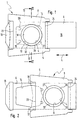
- ein erfindungsgemäßes Anschlußstück in Draufsicht auf seine dem Filterbeutel abgewandte Aussenseite (der Filterbeutel ist hier nicht dargestellt), wobei sich der Verschlußschieber in seiner der Offenstellung entsprechenden Ausgangsstellung befindet,
- Figur 2
- das Anschlußstück gemäß Figur 1, wobei der Verschlußschieber in seine Schließstellung gezogen worden ist,
- Figur 3
- die Anordnung nach Figur 1 im Querschnitt gemäß der Schnittlinie III-III in schematischer Darstellung, wobei auch die Filterbeutel-Vorderwand, auf die das Anschlußstück aufgeklebt ist, eingezeichnet und außerdem der staubsaugerseitige Dichtkörper angedeutet ist, und
- Figur 4
- eine Variante des Anschlußstücks gemäß den Figuren 1 bis 3 im der Figur 3 entsprechenden Querschnitt, bei der zwischen den beiden Materiallagen des Grundkörpers eine gelochte Dichtmembran angeordnet ist, die von dem Anlagering in der die Anlagefläche bildenden Stellung gehalten wird; ansonsten besteht Übereinstimmung mit dem Ausführungsbeispiel nach den Figuren 1 bis 3, so daß in Figur 4 mit Ausnahme der zusätzlichen Dichtmembran die gleichen Bezugsziffern eingetragen sind.
- In der Zeichnung ist von dem Filterbeutel, für den das Anschlußstück 1 gedacht ist bzw. an dem das Anschlußstück sitzt, nur die Vorderwand 2 angedeutet, die eine Eintrittsöffnung 3 enthält, in deren Bereich außen am Filterbeutel das Anschlußstück 1 so befestigt ist, daß sich eine vom Anschlußstück 1 gebildete Anschlußöffnung 4 an der Stelle der Eintrittsöffnung 3 befindet. Das Befestigen des Anschlußstücks 1 an der Filterbeutel-Vorderwand 2 erfolgt regelmäßig durch Ankleben.
- Der Filterbeutel besteht aus luftdurchlässigem Filtermaterial (Papier, Vlies usw.) und wird in ein staubabsaugendes Gerät, also in einen Staubsauger, eingesetzt. Dabei dient das Anschlußstück 1 zum Herstellen der Verbindung des Filterbeutels mit dem Staubsauger.
- Das Anschlußstück 1 wird im wesentlichen von einem am Filterbeutel feststehenden, im wesentlichen plattenförmige Gestalt aufweisenden Grundkörper 5 und einem an diesem gelagerten Verschlußschieber 6 gebildet. Der Umriß des Grundkörpers 5 kann rechteckähnlich oder in anderer Weise geformt sein, so daß man eine Anpassung an den jeweiligen Gerätetyp des Staubsaugers erhält.
- Der Grundkörper 5 weist zwei übereinander angeordnete, kartonartig steife Materiallagen 7, 8 auf, die regelmäßig aus Kartonmaterial bestehen. Eine der Materiallagen, die Materiallage 7 (nachstehend innere Materiallage genannt) ist der Filterbeutel-Vorderwand 2 zugewandt und an diese angeklebt, während die andere Materiallage, die äußere Materiallage 8, dem Filterbeutel abgewandt ist und die dem Beutel abgewandte Außenseite des Anschlußstücks 1 bildet. Der Grundkörper 5 enthält ferner die bereits erwähnte Anschlußöffnung 4, mit der das Anschlußstück 1 auf einen am Staubsauger sitzenden Anschlußstutzen aufgesteckt werden kann. Die Anschlußöffnung 4 wird durch eine entsprechende Lochung der beiden Materiallagen 7, 8 hergestellt, so daß an der inneren Materiallage 7 eine Lochung 9 und an der äußeren Materiallage 8 eine mit der Lochung 9 fluchtende Lochung 10 vorhanden ist.
- Der Verschlußschieber 6 ist zwischen den beiden Grundkörper-Materiallagen 7, 8 in seiner Längsrichtung L verschiebbar geführt und kann aus folienartig dünnem, flexiblem Material bestehen, wobei der Verschlußschieber 6 in seiner Längsrichtung L auch aus mehreren Bereichen unterschiedlicher Festigkeit zusammengesetzt sein kann, was im vorliegenden Zusammenhang jedoch nicht weiter interessiert. Zur Lagerung des Verschlußschiebers 6 bilden die beiden Materiallagen 7, 8 zwischen sich einen Führungsschlitz 11. Die Materiallagen 7, 8 sind beiderseits des Führungsschlitzes 11, d. h. beiderseits des in diesem geführten Verschlußschiebers 6, in den Bereichen 12, 13 fest miteinander verbunden, was regelmäßig durch Kleben erfolgt. Zwischen den beiden Bereichen 12, 13 sind die beiden Materiallagen 7, 8 unverbunden, so daß der Verschlußschieber 6 aufgenommen und in Längsrichtung L bewegt werden kann.
- Der Verschlußschieber 6 enthält eine der Anschlußöffnung 4 des Grundkörpers 5 zugeordnete Durchgangsöffnung 14. In seiner Ausgangsstellung, die er beim Einsetzen des Anschlußstücks 1 in den Staubsauger einnimmt, befindet sich der Verschlußschieber 6 in seiner Offenstellung (Figur 1), in der seine Durchgangsöffnung 14 an der Stelle der Anschlußöffnung 4 des Grundkörpers angeordnet ist, so daß diese und somit auch die Eintrittsöffnung 3 des Filterbeutels frei ist. Aus dieser Offenstellung kann der Verschlußschieber 6 in eine Schließstellung (Figur 2) bewegt werden, in der er die Anschlußöffnung 4 verschließt. Dieses Bewegen erfolgt beim Ausführungsbeispiel durch Ziehen des Verschlußschiebers 6 in Längsrichtung L.
- Der Verschlußschieber 6 weist in seiner beim Ausführungsbeispiel mit der Längsrichtung L zusammenfallenden Bewegungsrichtung einerseits der Durchgangsöffnung 14 einen Verschlußbereich 15 und andererseits der Durchgangsöffnung 14 einen außerhalb des Grundkörpers 5 angeordneten Handgriff 16 auf, der mit der Hand ergriffen werden kann. Zieht man in Figur 1 am Handgriff 16 nach links, gelangt der Verschlußbereich 15 an die Stelle der Anschlußöffnung 4 des Grundkörpers und verschließt diese. Der Verschlußschieber 6 kann, muß jedoch nicht unbedingt, auch mit seinem Verschlußbereich 15 aus dem Grundkörper 5 ragen, und zwar an der dem Handgriff 16 entgegengesetzten Grundkörperseite.
- In der Querschnittsdarstellung gemäß den Figuren 3 und 4 sind vom Verschlußschieber 6 nur die beiden beiderseits der Durchgangsöffnung 14 liegenden, stegartigen Verschlußschieberbereiche 17, 18 sichtbar.
- Damit der Verschlußschieber 6 beim Überführen in die Schließstellung nicht ganz aus dem Grundkörper 5 herausgezogen werden kann, läuft er gegen einen am Grundkörper 5 vorhandenen Anschlag. Beim Ausführungsbeispiel sind hierzu an der äußeren Materiallage 8 im Bereich der Durchgangsöffnung 14 des Verschlußschiebers 6 zwei Stanzzugen 19, 20 vorhanden, die durch die Durchgangsöffnung 14 des Verschlußschiebers 6 hindurch zur inneren Materiallage 7 hin abgebogen sind und dort jeweils in eine entsprechend angebrachte Ausnehmung eingreifen. Diese Stanzzungen 19, 20 durchqueren also den Führungsschlitz 11 für den Verschlußschieber 6. In der Schließstellung gemäß Figur 2 gelangt der betreffende Rand der Durchgangsöffnung 14 zur Anlage an diese Stanzzungen 19, 20 bzw. gleitet auf diese auf.
- Wie bereits erwähnt, sind die beiden Grundkörper-Materiallagen 7, 8 breiter als der Verschlußschieber 6 und beiderseits von diesem an den Seitenbereichen 12, 13 über die Grundkörperlänge hinweg miteinander verklebt. Um die Reibung zwischen den Grundkörper-Materiallagen 7, 8 und dem Verschlußschieber 6 zu verringern, kann der den Verschlußschieber führende Bereich mindestens einer der Materiallagen mittels beidseitig vom Verschlußschieber angebrachten Prägelinien 21, 22 etwas abgesetzt, d. h. von der jeweils anderen Materiallage etwas entfernt sein. Das Verschiebespiel für den Verschlußschieber könnte man jedoch auch auf andere Weise erreichen. Dies ist im vorliegenden Zusammenhang jedoch nicht weiter von Interesse.
- Der Führungsschlitz 11 ist an seinen beiden Enden 23, 24 offen, d. h. die beiden Materiallagen 7, 8 sind hier nicht aufeinander geklebt, damit der Verschlußschieber 6 austreten kann. Gegebenenfalls, wenn der Verschlußschieber mit seinem dem Handgriff entgegengesetzten Ende nicht aus dem Grundkörper ragen sollte, könnte man den Führungsschlitz an dem betreffenden Ende ebenfalls verschließen. In jedem Falle ist der Führungsschlitz aber zumindest am dem Handgriff 16 zugewandeten Ende offen.
- An den Führungsschlitzenden 23, 24 ist also das Filterbeutelinnere nicht staubdicht abgeschlossen, so daß hier bei in den Staubsauger eingesetztem Filterbeutel, wenn sich der Verschlußschieber in seiner Offenstellung befindet, ohne die nachstehend erläuterten Maßnahmen angesaugte Staubpartikel am Verschlußschieber vorbei in den den Filterbeutel aufnehmenden Raum des Staubsaugers gelangen und ihn verschmutzen können.
- In diesem Zusammenhang ist zunächst von Bedeutung, daß der Staubsauger, für den der dargestellte Filterbeutel gedacht ist, einen feststehenden Dichtkörper aufweist, dem eine an der Aussenseite des Grundkörpers 5 des Anschlußstücks 1 um die Anschlußöffnung 4 umlaufende Anlagefläche zugeordnet ist, die im in den Staubsauger eingesetzten Zustand an der zugewandten Dichtfläche 25 des am Staubsauger angeordneten Dichtkörpers anliegt, so daß hier eine um die Anschlußöffnung 4 umlaufende Ringdichtung gebildet wird. Beim Einsetzen des Filterbeutels in den Staubsauger wird das Anschlußstück 1 mit seiner Anschlußöffnung 4 auf einen staubsaugerseitigen Anschlußstutzen aufgesteckt, wobei die Grundkörper-Außenseite an der Dichtfläche 25 zur Anlage gelangt.
- Um nun einen endseitigen Staubaustritt an den Führungsschlitzenden zu vermeiden, ist an der Anschlußöffnung 4 des Anschlußstücks 1 an diesem ein von der inneren Materiallage 7 ausgehender, in oder durch die Lochung 10 der äußeren Materiallage 8 ragender Anlagering 26 angeordnet, der die sich gegen die geräteseitige Dichtfläche 25 legende Anlagefläche 27 bildet (Ausführungsbeispiel nach den Figuren 1 bis 3) oder ein die Anlagefläche 27a bildendes Dichtteil 28 in Stellung hält (Ausführungsbeispiel nach Figur 4). Der Anlagering 26 durchgreift also in der Offenstellung des Verschlußschiebers 6 dessen Durchgangsöffnung 14 und ragt bis zur dem Filterbeutel abgewandten Außenseite des Anschlußstücks 1 vor, so daß die Anschlußöffnung 4 über ihre axiale Länge und somit auch über den Führungsschlitz 11 hinweg umlaufend vom Anlagering 26 begrenzt wird, der somit eine den Eintritt von Staubpartikel in den Führungsschlitz 11 verhindernde Abdichtung bildet.
- Der etwa in der Ebene der von der äußeren Materiallage 8 gebildeten Anschlußstück-Außenseite liegende Bereich des Anlagerings 26 bildet also die Anlagefläche, die im in den Staubsauger eingesetzten Zustand an der geräteseitigen Dichtfläche 25 anliegt bzw. das Dichtteil 28 gegen die Dichtfläche 25 hält, so daß auch hier eine staubdichte Anordnung vorliegt. Der die Dichtfläche 25 bildende Dichtkörper kann aus elastischem Dichtmaterial sein.
- Beim Überführen des Verschlußschiebers 6 aus seiner Offenstellung in die Schließstellung muß sich der Verschlußbereich 15 des Verschlußschiebers 6 über die Anschlußöffnung 4 legen. Hierzu ist der Grundkörper 5 mit dem Anlagering 26 und/oder der Verschlußschieber 6 so flexibel gestaltet, daß der Verschlußschieber 6 über den Anlagering 26 hinweg in seine Schließstellung bewegt werden kann. Der Verschlußschieber lenkt dabei aus seiner ansonsten eingenommenen Ebene der axialen Abmessung des Anlagerings 26 entsprechend aus.
- Der Anlagering 26 bildet also sozusagen einen Ringsitz, der durch die äußere Materiallage 8 hindurch reicht und als Dichtsitz für die geräteseitige Dichtfläche 25 wirkt.
- Das bei dem Ausführungsbeispiel nach Figur 4 vorhandene Dichtteil 28 wird von einer an der Stelle der Anschlußöffnung 4 gelochten Dichtmembran 29 gebildet, die zwischen den beiden Materiallagen 7, 8 des Grundkörpers 5 festgelegt, zweckmäßigerweise an die Innenseite der äußeren Materiallage 8 geklebt ist. Diese Dichtmembran 29 steht ringartig in die Lochung 10 der äußeren Materiallage 8 vor und überdeckt den Anlagering 26. Die Dichtmembran 29 besteht aus elastischem Dichtmaterial.
- Der Anlagering 26 ist zweckmäßigerweise einstückig mit der inneren Materiallage 7 des Grundkörpers 5 verbunden. In diesem Zusammenhang weist die Lochung 9 der inneren Materiallage 7 einen kleineren Durchmesser als die Lochung 10 der äußeren Materiallage 8 auf, so daß ein nach radial innen über den Lochrand 30 der äußeren Materiallage 8 vorstehender Ringbereich der inneren Materiallage 7 gebildet wird, der zum in oder durch die Lochung 10 der äußeren Materiallage ragenden Anlagering 26 geformt ist. Der Anlagering 26 ist also sozusagen aus der sonstigen Ebene der inneren Materiallage 7 etwas ausgestülpt oder dergleichen. Dabei kann der den Anlagering 26 bildende Ringbereich der inneren Materiallage 7 am Lochrand 30 der äußeren Materiallage 8 in die Lochung 10 der äußeren Materiallage 8 gedrückt sein. Bei der Herstellung kann also so vorgegangen werden, daß man bei ansonsten fertigem Anschlußstück den Lochrand 30 der äußeren Materiallage 8 sozusagen als Form nimmt, in die man den den Anlagering 26 bildenden Ringbereich der inneren Materiallage 7 drückt.
Claims (4)
- Anschlußstück eines Filterbeuteis für Staubsauger, mit einem feststehenden, im wesentlichen plattenförmigen Grundkörper, der eine dem Beutel zugewandte innere Materiallage und eine dem Beutel abgewandte äußere Materiallage, diese Materiallagen insbesondere aus Kartonmaterial, aufweist, die übereinander angeordnet und beiderseits eines zwischen ihnen vorhandenen, endseitig offenen Führungsschlitzes miteinander verbunden sind, in dem ein aus dem Grundkörper ragender Verschlußschieber geführt ist, wobei der Grundkörper eine von fluchtenden Lochungen der Materiallagen gebildete Anschlußöffnung und der Verschlußschieber eine Durchgangsöffnung aufweist und der Verschlußschieber aus einer die Anschlußöffnung freigebenden Offenstellung, in der seine Durchgangsöffnung fluchtend zur Anschlußöffnung angeordnet ist, in eine die Anschlußöffnung verschließende Schließstellung bewegbar ist und wobei der Grundkörper an seiner dem Beutel abgewandten Außenseite eine um die Anschlußöffnung umlaufende Anlagefläche bildet, die im in den Staubsauger eingesetzten Zustand an einem Dichtkörper des Staubsaugers anliegt, dadurch gekennzeichnet, daß an der Anschlußöffnung (4) ein von der inneren Materiallage (7) ausgehender, in oder durch die Lochung (10) der äußeren Materiallage (8) ragender Anlagering (26) angeordnet ist, der die Anlagefläche (27) bildet oder ein die Anlagefläche (27a) bildendes Dichtteil (28) in Stellung hält, wobei der Grundkörper (5) mit dem Anlagering (26) und/oder der Verschlußschieber (6) so flexibel sind, daß der Verschlußschieber (6) über den Anlagering (26) hinweg in seine Schließstellung bewegbar ist.
- Anschlußstück nach Anspruch 1, dadurch gekennzeichnet, daß der Anlagering (26) einstückig mit der inneren Materiallage (7) des Grundkörpers (5) verbunden ist, indem die Lochung der inneren Materiallage (7) einen kleineren Durchmesser als die Lochung (10) der äußeren Materiallage (8) aufweist, so daß ein nach radial innen über den Lochrand (30) der Lochung (10) der äußeren Materiallage (8) vorstehender Ringbereich der inneren Materiallage (7) gebildet wird, der zum in oder durch die Lochung (10) der äußeren Materiallage (8) ragenden Anlagering (26) geformt ist.
- Anschlußstück nach Anspruch 2, dadurch gekennzeichnet, daß der den Anlagering (26) bildende Ringbereich der inneren Materiallage (7) am Lochrand (30) der äußeren Materiallage (8) in die Lochung (10) der äußeren Materiallage (8) gedrückt ist.
- Anschlußstück nach einem der Ansprüche 1 bis 3, dadurch gekennzeichnet, daß das Dichtteil (28) eine gelochte Dichtmembran (29) ist, die zwischen den beiden Materiallagen (7, 8) des Grundkörpers (5) festgelegt ist.
Applications Claiming Priority (2)
| Application Number | Priority Date | Filing Date | Title |
|---|---|---|---|
| DE29601812U DE29601812U1 (de) | 1996-02-03 | 1996-02-03 | Anschlußstück eines Filterbeutels für Staubsauger |
| DE29601812U | 1996-02-03 |
Publications (3)
| Publication Number | Publication Date |
|---|---|
| EP0787460A2 true EP0787460A2 (de) | 1997-08-06 |
| EP0787460A3 EP0787460A3 (de) | 1998-08-19 |
| EP0787460B1 EP0787460B1 (de) | 2001-07-18 |
Family
ID=8018912
Family Applications (1)
| Application Number | Title | Priority Date | Filing Date |
|---|---|---|---|
| EP96120553A Expired - Lifetime EP0787460B1 (de) | 1996-02-03 | 1996-12-20 | Anschlussstück eines Filterbeutels für Staubsauger |
Country Status (2)
| Country | Link |
|---|---|
| EP (1) | EP0787460B1 (de) |
| DE (2) | DE29601812U1 (de) |
Cited By (3)
| Publication number | Priority date | Publication date | Assignee | Title |
|---|---|---|---|---|
| EP2044874A2 (de) | 2007-10-01 | 2009-04-08 | BRANOfilter GmbH | Filterbeutel für Staubsauger |
| US7799107B2 (en) | 2006-03-15 | 2010-09-21 | Techtronic Floor Care Technology Limited | Self-sealing bag arrangement for a floor cleaning device |
| WO2015024513A1 (zh) * | 2013-08-20 | 2015-02-26 | 科沃斯机器人有限公司 | 自移动装置 |
Families Citing this family (2)
| Publication number | Priority date | Publication date | Assignee | Title |
|---|---|---|---|---|
| DE102005027078B4 (de) * | 2005-06-11 | 2007-12-13 | Jan-Robert Wulbrandt | Vorrichtung zur Befestigung von Filterbeuteln in Geräten |
| DE102007013279A1 (de) * | 2007-03-16 | 2008-09-25 | Gebrüder Voit GmbH | Halteplatte für Filtereinsatzbeutel, Faltzuschnitt für eine derartige Halteplatte, Filtereinsatzbeutel sowie Verfahren zum Verbinden einer Halteplatte mit einem Filtereinsatzbeutel |
Citations (4)
| Publication number | Priority date | Publication date | Assignee | Title |
|---|---|---|---|---|
| CH497165A (de) * | 1969-03-10 | 1970-10-15 | Siemens Elektrogeraete Gmbh | Filterbefestigung für Staubsauger |
| EP0179950A1 (de) * | 1984-11-01 | 1986-05-07 | Raymond Leslie Woodley | Dichtungsanordnungen |
| DE4237035A1 (de) * | 1992-11-03 | 1994-05-05 | Vorwerk Co Interholding | Staubfilterbeutel für einen Staubsauger |
| EP0623305A1 (de) * | 1993-05-07 | 1994-11-09 | Branofilter Gmbh | Filterbeutel für Staubsauger |
-
1996
- 1996-02-03 DE DE29601812U patent/DE29601812U1/de not_active Expired - Lifetime
- 1996-12-20 DE DE59607314T patent/DE59607314D1/de not_active Expired - Fee Related
- 1996-12-20 EP EP96120553A patent/EP0787460B1/de not_active Expired - Lifetime
Patent Citations (4)
| Publication number | Priority date | Publication date | Assignee | Title |
|---|---|---|---|---|
| CH497165A (de) * | 1969-03-10 | 1970-10-15 | Siemens Elektrogeraete Gmbh | Filterbefestigung für Staubsauger |
| EP0179950A1 (de) * | 1984-11-01 | 1986-05-07 | Raymond Leslie Woodley | Dichtungsanordnungen |
| DE4237035A1 (de) * | 1992-11-03 | 1994-05-05 | Vorwerk Co Interholding | Staubfilterbeutel für einen Staubsauger |
| EP0623305A1 (de) * | 1993-05-07 | 1994-11-09 | Branofilter Gmbh | Filterbeutel für Staubsauger |
Cited By (4)
| Publication number | Priority date | Publication date | Assignee | Title |
|---|---|---|---|---|
| US7799107B2 (en) | 2006-03-15 | 2010-09-21 | Techtronic Floor Care Technology Limited | Self-sealing bag arrangement for a floor cleaning device |
| EP2044874A2 (de) | 2007-10-01 | 2009-04-08 | BRANOfilter GmbH | Filterbeutel für Staubsauger |
| EP2044874A3 (de) * | 2007-10-01 | 2009-09-30 | BRANOfilter GmbH | Filterbeutel für Staubsauger |
| WO2015024513A1 (zh) * | 2013-08-20 | 2015-02-26 | 科沃斯机器人有限公司 | 自移动装置 |
Also Published As
| Publication number | Publication date |
|---|---|
| EP0787460A3 (de) | 1998-08-19 |
| DE29601812U1 (de) | 1996-03-14 |
| EP0787460B1 (de) | 2001-07-18 |
| DE59607314D1 (de) | 2001-08-23 |
Similar Documents
| Publication | Publication Date | Title |
|---|---|---|
| EP1917897B1 (de) | Anschlussstück für einen Staubfilterbeutel sowie mit einem solchen Anschlussstück ausgestatteter Staubfilterbeutel | |
| DE4315203C2 (de) | Filterbeutel für Staubsauger | |
| DE4339298C1 (de) | Filterbeutel für Staubsauger | |
| DE4002868C1 (en) | Vacuum cleaner filter bag - has connector made of several layers of cardboard with central opening and sliding closure | |
| EP0362624B1 (de) | Filter für Staubsauger | |
| EP2044874B1 (de) | Filterbeutel für Staubsauger | |
| EP1607034A1 (de) | Staubfilterbeutel und zugeordnete Adapterplatte | |
| DE3714388A1 (de) | Saugnapf | |
| DE202013103508U1 (de) | Staubsaugerbeutel | |
| DE102005041811A1 (de) | Staubsaugerbeutel mit Kunststoffflansch | |
| EP0787460B1 (de) | Anschlussstück eines Filterbeutels für Staubsauger | |
| EP0655217B1 (de) | Elektro-Staubsauger mit einer Aufnahmekammer für einen Staubbeutel | |
| DE202012102080U1 (de) | Mit einem luftdichten Behälter mit ebener Innenwand zusammenschliessbarer Deckel | |
| DE10203405B4 (de) | Filtervorrichtung für einen Staubsauger | |
| DE10138752C1 (de) | Vorrichtung zur Halterung eines Staubbeutels | |
| DE102019102357B4 (de) | Vorrichtung zur Absperrung oder Steuerung des Durchflusses von schmutzbeladener Luft, Reinigungsgerät und Behältnis zum Abtrennen und/oder Sammeln von Schmutz mit einer solchen Vorrichtung | |
| DE202004008971U1 (de) | Staubfilterbeutel | |
| EP3909487B1 (de) | Anordnung und verfahren zum betreiben einer anordnung | |
| EP0563869B1 (de) | Filtersackmuffe für einen Schmutzsauger | |
| DE102016220252A1 (de) | Staubfilterbeutel für einen Staubsauger | |
| DE202007014163U1 (de) | Filterbeutel für einen Staubsauger | |
| DE202008016299U1 (de) | Halteplatte | |
| DE4429342A1 (de) | Anschlußstück eines Filterbeutels für Staubsauger | |
| EP2910169B1 (de) | Staubsauger | |
| DE202011000084U1 (de) | Evakuierbares Aufbewahrungsbehältnis |
Legal Events
| Date | Code | Title | Description |
|---|---|---|---|
| PUAI | Public reference made under article 153(3) epc to a published international application that has entered the european phase |
Free format text: ORIGINAL CODE: 0009012 |
|
| AK | Designated contracting states |
Kind code of ref document: A2 Designated state(s): BE DE FR GB IT NL SE |
|
| PUAL | Search report despatched |
Free format text: ORIGINAL CODE: 0009013 |
|
| AK | Designated contracting states |
Kind code of ref document: A3 Designated state(s): BE DE FR GB IT NL SE |
|
| 17P | Request for examination filed |
Effective date: 19980720 |
|
| 17Q | First examination report despatched |
Effective date: 19991007 |
|
| GRAG | Despatch of communication of intention to grant |
Free format text: ORIGINAL CODE: EPIDOS AGRA |
|
| GRAG | Despatch of communication of intention to grant |
Free format text: ORIGINAL CODE: EPIDOS AGRA |
|
| GRAH | Despatch of communication of intention to grant a patent |
Free format text: ORIGINAL CODE: EPIDOS IGRA |
|
| GRAH | Despatch of communication of intention to grant a patent |
Free format text: ORIGINAL CODE: EPIDOS IGRA |
|
| GRAA | (expected) grant |
Free format text: ORIGINAL CODE: 0009210 |
|
| AK | Designated contracting states |
Kind code of ref document: B1 Designated state(s): BE DE FR GB IT NL SE |
|
| GBT | Gb: translation of ep patent filed (gb section 77(6)(a)/1977) |
Effective date: 20010718 |
|
| REF | Corresponds to: |
Ref document number: 59607314 Country of ref document: DE Date of ref document: 20010823 |
|
| ET | Fr: translation filed | ||
| REG | Reference to a national code |
Ref country code: GB Ref legal event code: IF02 |
|
| PLBE | No opposition filed within time limit |
Free format text: ORIGINAL CODE: 0009261 |
|
| STAA | Information on the status of an ep patent application or granted ep patent |
Free format text: STATUS: NO OPPOSITION FILED WITHIN TIME LIMIT |
|
| 26N | No opposition filed | ||
| PGFP | Annual fee paid to national office [announced via postgrant information from national office to epo] |
Ref country code: BE Payment date: 20051031 Year of fee payment: 10 |
|
| PGFP | Annual fee paid to national office [announced via postgrant information from national office to epo] |
Ref country code: DE Payment date: 20051122 Year of fee payment: 10 |
|
| PGFP | Annual fee paid to national office [announced via postgrant information from national office to epo] |
Ref country code: GB Payment date: 20051201 Year of fee payment: 10 |
|
| PGFP | Annual fee paid to national office [announced via postgrant information from national office to epo] |
Ref country code: SE Payment date: 20051207 Year of fee payment: 10 |
|
| PGFP | Annual fee paid to national office [announced via postgrant information from national office to epo] |
Ref country code: NL Payment date: 20051219 Year of fee payment: 10 |
|
| PGFP | Annual fee paid to national office [announced via postgrant information from national office to epo] |
Ref country code: FR Payment date: 20051220 Year of fee payment: 10 |
|
| PG25 | Lapsed in a contracting state [announced via postgrant information from national office to epo] |
Ref country code: SE Free format text: LAPSE BECAUSE OF NON-PAYMENT OF DUE FEES Effective date: 20061221 |
|
| PG25 | Lapsed in a contracting state [announced via postgrant information from national office to epo] |
Ref country code: BE Free format text: LAPSE BECAUSE OF NON-PAYMENT OF DUE FEES Effective date: 20061231 |
|
| PGFP | Annual fee paid to national office [announced via postgrant information from national office to epo] |
Ref country code: IT Payment date: 20061231 Year of fee payment: 11 |
|
| PG25 | Lapsed in a contracting state [announced via postgrant information from national office to epo] |
Ref country code: NL Free format text: LAPSE BECAUSE OF NON-PAYMENT OF DUE FEES Effective date: 20070701 |
|
| PG25 | Lapsed in a contracting state [announced via postgrant information from national office to epo] |
Ref country code: DE Free format text: LAPSE BECAUSE OF NON-PAYMENT OF DUE FEES Effective date: 20070703 |
|
| EUG | Se: european patent has lapsed | ||
| GBPC | Gb: european patent ceased through non-payment of renewal fee |
Effective date: 20061220 |
|
| NLV4 | Nl: lapsed or anulled due to non-payment of the annual fee |
Effective date: 20070701 |
|
| REG | Reference to a national code |
Ref country code: FR Ref legal event code: ST Effective date: 20070831 |
|
| PG25 | Lapsed in a contracting state [announced via postgrant information from national office to epo] |
Ref country code: GB Free format text: LAPSE BECAUSE OF NON-PAYMENT OF DUE FEES Effective date: 20061220 |
|
| BERE | Be: lapsed |
Owner name: *BRANOFILTER G.M.B.H. Effective date: 20061231 |
|
| PG25 | Lapsed in a contracting state [announced via postgrant information from national office to epo] |
Ref country code: FR Free format text: LAPSE BECAUSE OF NON-PAYMENT OF DUE FEES Effective date: 20070102 |
|
| PG25 | Lapsed in a contracting state [announced via postgrant information from national office to epo] |
Ref country code: IT Free format text: LAPSE BECAUSE OF NON-PAYMENT OF DUE FEES Effective date: 20071220 |