EP0787460A2 - Pièce de raccordement pour sac à poussière d'aspirateur - Google Patents
Pièce de raccordement pour sac à poussière d'aspirateur Download PDFInfo
- Publication number
- EP0787460A2 EP0787460A2 EP96120553A EP96120553A EP0787460A2 EP 0787460 A2 EP0787460 A2 EP 0787460A2 EP 96120553 A EP96120553 A EP 96120553A EP 96120553 A EP96120553 A EP 96120553A EP 0787460 A2 EP0787460 A2 EP 0787460A2
- Authority
- EP
- European Patent Office
- Prior art keywords
- material layer
- base body
- perforation
- ring
- slide
- Prior art date
- Legal status (The legal status is an assumption and is not a legal conclusion. Google has not performed a legal analysis and makes no representation as to the accuracy of the status listed.)
- Granted
Links
Images

Classifications
-
- A—HUMAN NECESSITIES
- A47—FURNITURE; DOMESTIC ARTICLES OR APPLIANCES; COFFEE MILLS; SPICE MILLS; SUCTION CLEANERS IN GENERAL
- A47L—DOMESTIC WASHING OR CLEANING; SUCTION CLEANERS IN GENERAL
- A47L9/00—Details or accessories of suction cleaners, e.g. mechanical means for controlling the suction or for effecting pulsating action; Storing devices specially adapted to suction cleaners or parts thereof; Carrying-vehicles specially adapted for suction cleaners
- A47L9/10—Filters; Dust separators; Dust removal; Automatic exchange of filters
- A47L9/14—Bags or the like; Rigid filtering receptacles; Attachment of, or closures for, bags or receptacles
- A47L9/1427—Means for mounting or attaching bags or filtering receptacles in suction cleaners; Adapters
- A47L9/1436—Connecting plates, e.g. collars, end closures
- A47L9/1445—Connecting plates, e.g. collars, end closures with closure means
Definitions
- the invention relates to a connection piece of a filter bag for vacuum cleaners, with a fixed, substantially plate-shaped base body, which has an inner material layer facing the bag and an outer material layer facing away from the bag, these material layers, in particular made of cardboard material, which are arranged one above the other and one between them
- Existing, open-ended guide slot are connected to each other, in which a locking slide projecting from the base body is guided, the base body having a connection opening formed by aligned perforations in the material layers and the locking slide having a through opening and the locking slide from an open position releasing the connection opening, in its Through opening is arranged in alignment with the connection opening, can be moved into a closed position closing the connection opening and the base body on its side facing away from the bag n forms a peripheral contact surface around the connection opening, which abuts a sealing body of the vacuum cleaner when inserted into the vacuum cleaner.
- filter bags - including larger filter bags or the like - are used to collect the dust that accumulates.
- a suction flow is generated by means of a vacuum cleaner fan, which draws the dust into a suction channel, suction hose or the like and from there conveys it through the dust inlet opening into the filter bag in question.
- the dust contained in the sucked-in air is retained by the filter bag wall, while the dust-free air flow penetrates the filter bag wall and is then blown out into the environment. If the filter bag is full, it is removed and can be thrown away.
- the filter bag is attached to the vacuum cleaner by means of the connector attached to the filter bag in the area of its inlet opening, which is attached in such a way that the connection opening formed by its base body coincides with the inlet opening of the actual filter bag, so that the dust air can be introduced.
- the mentioned connection opening and thus also the inlet opening of the filter bag can then be closed when the filter bag is removed from the vacuum cleaner. In this way, no dust can escape into the environment from the removed filter bag.
- the vacuum cleaner-side sealing body is used, which is arranged in such a way that it lies on the outside of the connecting piece around the connecting opening, so that there is an annular sealing of the dust path at this point.
- the guide slot of the connecting piece receiving the slide valve is open at its ends corresponding to the direction of movement of the slide valve, since the slide valve protrudes from the base body here so that it can be gripped by hand. It is indeed a very flat guide slot which corresponds essentially to the material thickness of the closure slide. Nevertheless, dust particles, especially if it is fine dust, can escape to the outside via the open guide slot ends and contaminate the filter bag receiving space of the vacuum cleaner.
- the present invention is therefore based on the object to provide a connector of the type mentioned, in which the tightness against dust leakage is improved. This is to be achieved with the simplest possible means, which is particularly important in view of the fact that this is a mass article.
- this object is achieved in that at the connection opening a starting point from the inner material layer, in or through the perforation of the outer layer of material projecting contact ring is arranged, which forms the contact surface or holds the sealing surface forming the contact surface in position, the base body with the contact ring and / or the locking slide being so flexible that the locking slide over the contact ring in its closed position is movable.
- This contact ring or the sealing part held by it thus seals on the one hand on the end face against the vacuum cleaner-side sealing body and on the other circumferentially around the guide slot of the closure slide, so that no dust can get into the vacuum cleaner via the guide slot.
- the bearing ring is expediently connected in one piece to the inner material layer of the base body in that the perforation of the inner material layer has a smaller diameter than the perforation of the outer material layer, so that an annular region of the inner material layer projecting radially inward beyond the perforated edge of the perforation of the outer material layer is formed is formed, which is formed in or through the perforation of the outer layer of material bearing ring.
- This is a very simple solution in terms of construction and costs.
- the ring area of the inner layer of material forming the contact ring can be pressed at the hole edge of the outer layer of material. In this way, the hole edge of the outer layer of material can be used, so to speak, as a shaping part when pressing in the abutment ring.
- the sealing part can be a perforated sealing membrane which is fixed between the two material layers of the base body.
- connection piece 1 is regularly attached to the filter bag front wall 2 by gluing.
- the filter bag consists of air-permeable filter material (paper, fleece, etc.) and is used in a dust-extracting device, i.e. in a vacuum cleaner.
- the connector 1 is used to connect the filter bag to the vacuum cleaner.
- the connecting piece 1 is essentially formed by a base body 5, which is fixed to the filter bag, has an essentially plate-like shape, and a closure slide 6 mounted thereon.
- the outline of the base body 5 can be shaped like a rectangle or in some other way, so that an adaptation to the respective device type of the vacuum cleaner is obtained.
- the base body 5 has two superposed, cardboard-like rigid layers of material 7, 8, which regularly consist of cardboard material.
- One of the material layers, the material layer 7 (hereinafter referred to as the inner material layer) faces the filter bag front wall 2 and is glued to it, while the other material layer, the outer material layer 8, faces away from the filter bag and forms the outside of the connector 1 facing away from the bag.
- the base body 5 also contains the connection opening 4 already mentioned, with which the connection piece 1 can be plugged onto a connection piece seated on the vacuum cleaner.
- the connection opening 4 is produced by a corresponding perforation of the two material layers 7, 8, so that there is a perforation 9 on the inner material layer 7 and a perforation 10 aligned with the perforation 9 is provided on the outer material layer 8.
- the slide valve 6 is slidably guided in the longitudinal direction L between the two base material layers 7, 8 and can consist of thin, flexible material in the form of a film, the slide valve 6 also in its longitudinal direction L. can be composed of several areas of different strength, which is of no further interest in the present context.
- the two material layers 7, 8 form a guide slot 11 between them.
- the material layers 7, 8 are firmly connected to each other in the areas 12, 13 on both sides of the guide slot 11, ie on both sides of the slide slide 6 guided therein, which is regular done by gluing. Between the two areas 12, 13, the two layers of material 7, 8 are not connected, so that the locking slide 6 can be received and moved in the longitudinal direction L.
- the closure slide 6 contains a through opening 14 assigned to the connection opening 4 of the base body 5.
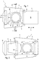
- the closure slide 6 In its initial position, which it assumes when the connection piece 1 is inserted into the vacuum cleaner, the closure slide 6 is in its open position (FIG. 1) in which its through opening 14 is located the location of the connection opening 4 of the base body is arranged so that this and thus also the inlet opening 3 of the filter bag is free. From this open position, the closure slide 6 can be moved into a closed position (FIG. 2) in which it closes the connection opening 4. This movement takes place in the exemplary embodiment by pulling the slide slide 6 in the longitudinal direction L.
- the closure slide 6 has on the one hand the through opening 14 a closure region 15 and, on the other hand, the through-opening 14 has a handle 16 arranged outside the base body 5, which handle can be gripped by hand. If one pulls to the left in FIG. 1 on the handle 16, the closure region 15 takes the place of the connection opening 4 of the base body and closes it.
- the locking slide 6 can, but need not necessarily, also protrude from the base body 5 with its locking region 15, specifically on the side of the base body opposite the handle 16.
- the closure slide 6 cannot be pulled completely out of the base body 5 when it is moved into the closed position, it runs against an abutment on the base body 5.
- These punch tongues 19, 20 thus pass through the guide slot 11 for the closure slide 6. In the closed position according to FIG. 2, the relevant edge of the through opening 14 comes to bear against these punch tongues 19, 20 or slides onto them.
- the two base body material layers 7, 8 are wider than the closure slide 6 and are glued together on both sides of it at the side regions 12, 13 over the length of the base body.
- the area guiding the slide valve at least one of the material layers can be set off somewhat by means of embossing lines 21, 22 attached to the slide valve on both sides, i. H. be somewhat distant from the other material layer.
- the sliding game for the slide gate could also be achieved in other ways. However, this is of no further interest in the present context.
- the guide slot 11 is open at both ends 23, 24, i. H. the two layers of material 7, 8 are not glued to one another here so that the slide 6 can emerge. If necessary, if the locking slide should not protrude from the base body with its end opposite the handle, the guide slot could also be closed at the end in question. In any case, the guide slot is open at least at the end facing the handle 16.
- the interior of the filter bag is therefore not dust-tight, so that when the filter bag is inserted into the vacuum cleaner, when the closure slide is in its open position, dust particles sucked in on the closure slide without the measures explained below pass into the space of the vacuum cleaner that holds the filter bag and can contaminate it.
- the vacuum cleaner for which the filter bag shown is intended has a fixed sealing body, which is associated with a contact surface that extends around the connection opening 4 on the outside of the base body 5 of the connection piece 1 and which is in the vacuum cleaner inserted state rests on the facing sealing surface 25 of the sealing body arranged on the vacuum cleaner, so that here an annular seal is formed around the connection opening 4.
- the connection piece 1 is plugged with its connection opening 4 onto a connection piece on the vacuum cleaner side, the base body outside coming into contact with the sealing surface 25.
- connection ring 26 which extends from the inner material layer 7 and projects into or through the perforation 10 of the outer material layer 8, is arranged at the connection opening 4 of the connecting piece 1 Forms sealing surface 25 laying contact surface 27 (embodiment according to FIGS. 1 to 3) or holds a sealing part 28 forming contact surface 27a in position (embodiment according to FIG. 4).
- the abutment ring 26 In the open position of the closure slide 6, the abutment ring 26 thus passes through its through opening 14 and extends as far as the filter bag facing away Outside of the connector 1 in front, so that the connection opening 4 over its axial length and thus also over the guide slot 11 is bounded by the abutment ring 26, which thus forms a seal preventing the entry of dust particles into the guide slot 11.
- the sealing body forming the sealing surface 25 can be made of elastic sealing material.
- the closure region 15 of the closure slide 6 must lie over the connection opening 4.
- the base body 5 with the contact ring 26 and / or the locking slide 6 is designed so flexibly that the locking slide 6 can be moved over the contact ring 26 into its closed position.
- the slide valve deflects from its otherwise occupied level in accordance with the axial dimension of the abutment ring 26.
- the contact ring 26 thus forms, so to speak, an annular seat which extends through the outer material layer 8 and acts as a sealing seat for the sealing surface 25 on the device side.
- the sealing part 28 present in the exemplary embodiment according to FIG. 4 is formed by a sealing membrane 29 perforated at the location of the connection opening 4, which is fixed between the two material layers 7, 8 of the base body 5, and is advantageously glued to the inside of the outer material layer 8.
- This sealing membrane 29 protrudes like a ring into the perforation 10 of the outer material layer 8 and covers the contact ring 26.
- the sealing membrane 29 consists of elastic sealing material.
- the bearing ring 26 is expediently connected in one piece to the inner material layer 7 of the base body 5.
- the perforation 9 of the inner layer of material 7 has a smaller diameter than the perforation 10 of the outer layer of material 8, so that an annular region of the inner layer of material 7 protruding radially inward beyond the hole edge 30 of the outer layer of material 8 is formed or is formed by the perforation 10 of the outer material layer projecting abutment ring 26.
- the contact ring 26 is thus, as it were, somewhat protruded from the other level of the inner material layer 7 or the like.
- the ring area of the inner material layer 7 forming the contact ring 26 at the hole edge 30 of the outer material layer 8 can be pressed into the perforation 10 of the outer material layer 8.
- the procedure can thus be such that, with an otherwise finished connecting piece, the hole edge 30 of the outer material layer 8 is taken as a form, so to speak, into which the ring region of the inner material layer 7 forming the contact ring 26 is pressed.
Landscapes
- Engineering & Computer Science (AREA)
- Mechanical Engineering (AREA)
- Filters For Electric Vacuum Cleaners (AREA)
Applications Claiming Priority (2)
| Application Number | Priority Date | Filing Date | Title |
|---|---|---|---|
| DE29601812U | 1996-02-03 | ||
| DE29601812U DE29601812U1 (de) | 1996-02-03 | 1996-02-03 | Anschlußstück eines Filterbeutels für Staubsauger |
Publications (3)
| Publication Number | Publication Date |
|---|---|
| EP0787460A2 true EP0787460A2 (fr) | 1997-08-06 |
| EP0787460A3 EP0787460A3 (fr) | 1998-08-19 |
| EP0787460B1 EP0787460B1 (fr) | 2001-07-18 |
Family
ID=8018912
Family Applications (1)
| Application Number | Title | Priority Date | Filing Date |
|---|---|---|---|
| EP96120553A Expired - Lifetime EP0787460B1 (fr) | 1996-02-03 | 1996-12-20 | Pièce de raccordement pour sac à poussière d'aspirateur |
Country Status (2)
| Country | Link |
|---|---|
| EP (1) | EP0787460B1 (fr) |
| DE (2) | DE29601812U1 (fr) |
Cited By (3)
| Publication number | Priority date | Publication date | Assignee | Title |
|---|---|---|---|---|
| EP2044874A2 (fr) | 2007-10-01 | 2009-04-08 | BRANOfilter GmbH | Sac filtrant pour aspirateur |
| US7799107B2 (en) | 2006-03-15 | 2010-09-21 | Techtronic Floor Care Technology Limited | Self-sealing bag arrangement for a floor cleaning device |
| WO2015024513A1 (fr) * | 2013-08-20 | 2015-02-26 | 科沃斯机器人有限公司 | Dispositif automoteur |
Families Citing this family (2)
| Publication number | Priority date | Publication date | Assignee | Title |
|---|---|---|---|---|
| DE102005027078B4 (de) * | 2005-06-11 | 2007-12-13 | Jan-Robert Wulbrandt | Vorrichtung zur Befestigung von Filterbeuteln in Geräten |
| DE102007013279A1 (de) * | 2007-03-16 | 2008-09-25 | Gebrüder Voit GmbH | Halteplatte für Filtereinsatzbeutel, Faltzuschnitt für eine derartige Halteplatte, Filtereinsatzbeutel sowie Verfahren zum Verbinden einer Halteplatte mit einem Filtereinsatzbeutel |
Citations (4)
| Publication number | Priority date | Publication date | Assignee | Title |
|---|---|---|---|---|
| CH497165A (de) * | 1969-03-10 | 1970-10-15 | Siemens Elektrogeraete Gmbh | Filterbefestigung für Staubsauger |
| EP0179950A1 (fr) * | 1984-11-01 | 1986-05-07 | Raymond Leslie Woodley | Agencement d'étanchéité |
| DE4237035A1 (de) * | 1992-11-03 | 1994-05-05 | Vorwerk Co Interholding | Staubfilterbeutel für einen Staubsauger |
| EP0623305A1 (fr) * | 1993-05-07 | 1994-11-09 | Branofilter Gmbh | Sac à poussières pour aspirateur |
-
1996
- 1996-02-03 DE DE29601812U patent/DE29601812U1/de not_active Expired - Lifetime
- 1996-12-20 EP EP96120553A patent/EP0787460B1/fr not_active Expired - Lifetime
- 1996-12-20 DE DE59607314T patent/DE59607314D1/de not_active Expired - Fee Related
Patent Citations (4)
| Publication number | Priority date | Publication date | Assignee | Title |
|---|---|---|---|---|
| CH497165A (de) * | 1969-03-10 | 1970-10-15 | Siemens Elektrogeraete Gmbh | Filterbefestigung für Staubsauger |
| EP0179950A1 (fr) * | 1984-11-01 | 1986-05-07 | Raymond Leslie Woodley | Agencement d'étanchéité |
| DE4237035A1 (de) * | 1992-11-03 | 1994-05-05 | Vorwerk Co Interholding | Staubfilterbeutel für einen Staubsauger |
| EP0623305A1 (fr) * | 1993-05-07 | 1994-11-09 | Branofilter Gmbh | Sac à poussières pour aspirateur |
Cited By (4)
| Publication number | Priority date | Publication date | Assignee | Title |
|---|---|---|---|---|
| US7799107B2 (en) | 2006-03-15 | 2010-09-21 | Techtronic Floor Care Technology Limited | Self-sealing bag arrangement for a floor cleaning device |
| EP2044874A2 (fr) | 2007-10-01 | 2009-04-08 | BRANOfilter GmbH | Sac filtrant pour aspirateur |
| EP2044874A3 (fr) * | 2007-10-01 | 2009-09-30 | BRANOfilter GmbH | Sac filtrant pour aspirateur |
| WO2015024513A1 (fr) * | 2013-08-20 | 2015-02-26 | 科沃斯机器人有限公司 | Dispositif automoteur |
Also Published As
| Publication number | Publication date |
|---|---|
| EP0787460A3 (fr) | 1998-08-19 |
| EP0787460B1 (fr) | 2001-07-18 |
| DE59607314D1 (de) | 2001-08-23 |
| DE29601812U1 (de) | 1996-03-14 |
Similar Documents
| Publication | Publication Date | Title |
|---|---|---|
| EP1917897B1 (fr) | Pièce de raccordement pour un sac antipoussière ainsi que sac antipoussière doté d'une telle pièce de raccordement | |
| DE4315203C2 (de) | Filterbeutel für Staubsauger | |
| DE4339298C1 (de) | Filterbeutel für Staubsauger | |
| DE4002868C1 (en) | Vacuum cleaner filter bag - has connector made of several layers of cardboard with central opening and sliding closure | |
| EP1607034A1 (fr) | Sac filtrant à poussière et sa plaque adaptatrice associée | |
| DE3714388A1 (de) | Saugnapf | |
| DE102014109596A1 (de) | Staubsaugerbeutel | |
| DE3833799A1 (de) | Filter fuer staubsauger | |
| DE102005041811A1 (de) | Staubsaugerbeutel mit Kunststoffflansch | |
| EP0787460B1 (fr) | Pièce de raccordement pour sac à poussière d'aspirateur | |
| DE10203405B4 (de) | Filtervorrichtung für einen Staubsauger | |
| DE202012102080U1 (de) | Mit einem luftdichten Behälter mit ebener Innenwand zusammenschliessbarer Deckel | |
| EP0655217A1 (fr) | Aspirateur avec conteneur pour sac à poussières | |
| DE20005448U1 (de) | Halteplatte eines Staubsauger-Filterbeutels | |
| DE10138752C1 (de) | Vorrichtung zur Halterung eines Staubbeutels | |
| EP3749160B1 (fr) | Dispositif de reception de particules, dispositif et procede pour faire fonctionner un dispositif | |
| DE202004008971U1 (de) | Staubfilterbeutel | |
| DE102016220252A1 (de) | Staubfilterbeutel für einen Staubsauger | |
| DE202007014163U1 (de) | Filterbeutel für einen Staubsauger | |
| DE202008016299U1 (de) | Halteplatte | |
| DE4429342A1 (de) | Anschlußstück eines Filterbeutels für Staubsauger | |
| EP2910169B1 (fr) | Aspirateur | |
| EP0563869A1 (fr) | Sac à poussières pour aspirateur | |
| DE29511029U1 (de) | Anschlußstück eines Filterbeutels für Staubsauger | |
| DE20200551U1 (de) | Anschlussstück eines Staubfilterbeutels |
Legal Events
| Date | Code | Title | Description |
|---|---|---|---|
| PUAI | Public reference made under article 153(3) epc to a published international application that has entered the european phase |
Free format text: ORIGINAL CODE: 0009012 |
|
| AK | Designated contracting states |
Kind code of ref document: A2 Designated state(s): BE DE FR GB IT NL SE |
|
| PUAL | Search report despatched |
Free format text: ORIGINAL CODE: 0009013 |
|
| AK | Designated contracting states |
Kind code of ref document: A3 Designated state(s): BE DE FR GB IT NL SE |
|
| 17P | Request for examination filed |
Effective date: 19980720 |
|
| 17Q | First examination report despatched |
Effective date: 19991007 |
|
| GRAG | Despatch of communication of intention to grant |
Free format text: ORIGINAL CODE: EPIDOS AGRA |
|
| GRAG | Despatch of communication of intention to grant |
Free format text: ORIGINAL CODE: EPIDOS AGRA |
|
| GRAH | Despatch of communication of intention to grant a patent |
Free format text: ORIGINAL CODE: EPIDOS IGRA |
|
| GRAH | Despatch of communication of intention to grant a patent |
Free format text: ORIGINAL CODE: EPIDOS IGRA |
|
| GRAA | (expected) grant |
Free format text: ORIGINAL CODE: 0009210 |
|
| AK | Designated contracting states |
Kind code of ref document: B1 Designated state(s): BE DE FR GB IT NL SE |
|
| GBT | Gb: translation of ep patent filed (gb section 77(6)(a)/1977) |
Effective date: 20010718 |
|
| REF | Corresponds to: |
Ref document number: 59607314 Country of ref document: DE Date of ref document: 20010823 |
|
| ET | Fr: translation filed | ||
| REG | Reference to a national code |
Ref country code: GB Ref legal event code: IF02 |
|
| PLBE | No opposition filed within time limit |
Free format text: ORIGINAL CODE: 0009261 |
|
| STAA | Information on the status of an ep patent application or granted ep patent |
Free format text: STATUS: NO OPPOSITION FILED WITHIN TIME LIMIT |
|
| 26N | No opposition filed | ||
| PGFP | Annual fee paid to national office [announced via postgrant information from national office to epo] |
Ref country code: BE Payment date: 20051031 Year of fee payment: 10 |
|
| PGFP | Annual fee paid to national office [announced via postgrant information from national office to epo] |
Ref country code: DE Payment date: 20051122 Year of fee payment: 10 |
|
| PGFP | Annual fee paid to national office [announced via postgrant information from national office to epo] |
Ref country code: GB Payment date: 20051201 Year of fee payment: 10 |
|
| PGFP | Annual fee paid to national office [announced via postgrant information from national office to epo] |
Ref country code: SE Payment date: 20051207 Year of fee payment: 10 |
|
| PGFP | Annual fee paid to national office [announced via postgrant information from national office to epo] |
Ref country code: NL Payment date: 20051219 Year of fee payment: 10 |
|
| PGFP | Annual fee paid to national office [announced via postgrant information from national office to epo] |
Ref country code: FR Payment date: 20051220 Year of fee payment: 10 |
|
| PG25 | Lapsed in a contracting state [announced via postgrant information from national office to epo] |
Ref country code: SE Free format text: LAPSE BECAUSE OF NON-PAYMENT OF DUE FEES Effective date: 20061221 |
|
| PG25 | Lapsed in a contracting state [announced via postgrant information from national office to epo] |
Ref country code: BE Free format text: LAPSE BECAUSE OF NON-PAYMENT OF DUE FEES Effective date: 20061231 |
|
| PGFP | Annual fee paid to national office [announced via postgrant information from national office to epo] |
Ref country code: IT Payment date: 20061231 Year of fee payment: 11 |
|
| PG25 | Lapsed in a contracting state [announced via postgrant information from national office to epo] |
Ref country code: NL Free format text: LAPSE BECAUSE OF NON-PAYMENT OF DUE FEES Effective date: 20070701 |
|
| PG25 | Lapsed in a contracting state [announced via postgrant information from national office to epo] |
Ref country code: DE Free format text: LAPSE BECAUSE OF NON-PAYMENT OF DUE FEES Effective date: 20070703 |
|
| EUG | Se: european patent has lapsed | ||
| GBPC | Gb: european patent ceased through non-payment of renewal fee |
Effective date: 20061220 |
|
| NLV4 | Nl: lapsed or anulled due to non-payment of the annual fee |
Effective date: 20070701 |
|
| REG | Reference to a national code |
Ref country code: FR Ref legal event code: ST Effective date: 20070831 |
|
| PG25 | Lapsed in a contracting state [announced via postgrant information from national office to epo] |
Ref country code: GB Free format text: LAPSE BECAUSE OF NON-PAYMENT OF DUE FEES Effective date: 20061220 |
|
| BERE | Be: lapsed |
Owner name: *BRANOFILTER G.M.B.H. Effective date: 20061231 |
|
| PG25 | Lapsed in a contracting state [announced via postgrant information from national office to epo] |
Ref country code: FR Free format text: LAPSE BECAUSE OF NON-PAYMENT OF DUE FEES Effective date: 20070102 |
|
| PG25 | Lapsed in a contracting state [announced via postgrant information from national office to epo] |
Ref country code: IT Free format text: LAPSE BECAUSE OF NON-PAYMENT OF DUE FEES Effective date: 20071220 |