EP0787460B1 - Pièce de raccordement pour sac à poussière d'aspirateur - Google Patents
Pièce de raccordement pour sac à poussière d'aspirateur Download PDFInfo
- Publication number
- EP0787460B1 EP0787460B1 EP96120553A EP96120553A EP0787460B1 EP 0787460 B1 EP0787460 B1 EP 0787460B1 EP 96120553 A EP96120553 A EP 96120553A EP 96120553 A EP96120553 A EP 96120553A EP 0787460 B1 EP0787460 B1 EP 0787460B1
- Authority
- EP
- European Patent Office
- Prior art keywords
- material layer
- base body
- perforation
- slide
- vacuum cleaner
- Prior art date
- Legal status (The legal status is an assumption and is not a legal conclusion. Google has not performed a legal analysis and makes no representation as to the accuracy of the status listed.)
- Expired - Lifetime
Links
Images

Classifications
-
- A—HUMAN NECESSITIES
- A47—FURNITURE; DOMESTIC ARTICLES OR APPLIANCES; COFFEE MILLS; SPICE MILLS; SUCTION CLEANERS IN GENERAL
- A47L—DOMESTIC WASHING OR CLEANING; SUCTION CLEANERS IN GENERAL
- A47L9/00—Details or accessories of suction cleaners, e.g. mechanical means for controlling the suction or for effecting pulsating action; Storing devices specially adapted to suction cleaners or parts thereof; Carrying-vehicles specially adapted for suction cleaners
- A47L9/10—Filters; Dust separators; Dust removal; Automatic exchange of filters
- A47L9/14—Bags or the like; Rigid filtering receptacles; Attachment of, or closures for, bags or receptacles
- A47L9/1427—Means for mounting or attaching bags or filtering receptacles in suction cleaners; Adapters
- A47L9/1436—Connecting plates, e.g. collars, end closures
- A47L9/1445—Connecting plates, e.g. collars, end closures with closure means
Definitions
- the invention relates to a connector of a filter bag for vacuum cleaners, with a fixed, essentially plate-shaped Basic body, the inner one facing the bag Material layer and an outer material layer facing away from the bag, has these layers of material, in particular of cardboard material, which are arranged one above the other and on both sides one between their existing, open end guide slot are connected to one another in which a protruding from the base body Locking slide is guided, the base body a connection opening formed by aligned perforations in the material layers and the slide valve has a through opening has and the slide valve from a connection opening releasing open position, in its through opening is aligned with the connection opening, in a connection opening closing position is movable and the base body on its outside facing away from the bag forms a contact surface surrounding the connection opening, the one in the state in the vacuum cleaner Sealing body of the vacuum cleaner rests.
- Vacuum cleaners are used to collect the accumulated Dusty filter bags - including larger filter bags or to understand - used. Doing so generates a suction flow by means of a vacuum cleaner fan, which the dust into a suction channel, suction hose or the like pulls and from there through the dust inlet opening in the concerned Filter bag promotes. The one in the sucked air dust contained is retained by the filter bag wall, during the dust-free air flow the filter bag wall penetrated and then blown into the environment. If the filter bag is full, it is removed and can be thrown away become.
- a exclusion piece of the type mentioned is from the EP-A-0 623 305 known. This is done Fix the filter bag on the vacuum cleaner using the attached to the filter bag in the area of its inlet opening Connector that is attached so that the from its base body formed connection opening with the inlet opening of the actual filter bag, so that the Dust air can be introduced. With the help of the slide can then the mentioned connection opening and thus also the inlet opening of the filter bag is closed, when the filter bag is removed from the vacuum cleaner. On this way no dust can be removed from the removed filter bag escape into the environment.
- the guide slot of the connector receiving the slide is however at its the direction of movement of the Slider corresponding ends open because of the slider protrudes from the base here so that it Hand can be taken. Although it is a very flat, essentially the material thickness of the slide gate corresponding guide slot. Nevertheless, dust particles, especially if the dust is fine, get out through the open guide slot ends and contaminate the filter bag receiving area of the vacuum cleaner.
- the present invention is therefore based on the object to create a connector of the type mentioned at which improves the tightness against dust leakage. This should be achieved with the simplest possible means, what is particularly important with regard to this, that this is a mass article.
- connection opening of a starting from the inner material layer bearing ring protruding in or through the perforation of the outer material layer is arranged, which forms the contact surface or a holds the sealing surface forming part in position, whereby the base body with the contact ring and / or the locking slide are so flexible that the locking slide over the bearing ring is movable away into its closed position.
- This contact ring or the sealing part held by it in position seals on the one hand against the vacuum cleaner side Sealing body and the other around the circumference Guide slot of the slide gate, so that also on the Guide slot no dust can get into the vacuum cleaner.
- the bearing ring is expediently in one piece with the inner ring Material layer of the base body connected by the perforation of the inner material layer a smaller diameter than the perforation the outer layer of material, so that a radial inside over the perforated edge of the perforation of the outer material layer protruding ring area of the inner material layer is formed becomes that in or through the perforation of the outer material layer projecting bearing ring is shaped.
- the ring can forming ring area of the inner material layer at the edge of the hole the outer layer of material. In this way can in the manufacture of the hole edge of the outer layer of material so to speak as a shaping part when pressing the bearing ring be used.
- the sealing part can be a perforated sealing membrane which between the two material layers of the base body is.
- the filter bag is made of air-permeable filter material (Paper, fleece, etc.) and is placed in a dust-extracting device, so used in a vacuum cleaner.
- the connector serves 1 for connecting the filter bag with the vacuum cleaner.
- the connector 1 is essentially one of the filter bag fixed, essentially plate-like shape having base body 5 and a locking slide mounted on this 6 formed.
- the outline of the base body 5 can be shaped like a rectangle or in another way, so that one receives an adaptation to the respective device type of the vacuum cleaner.
- the base body 5 has two cardboard-like ones arranged one above the other rigid material layers 7, 8, which are regularly made of cardboard material consist.
- One of the material layers, the material layer 7 (hereinafter referred to as the inner material layer) is the filter bag front wall 2 facing and glued to this while the other Material layer, the outer material layer 8, the filter bag is facing away and the outside of the connector facing away from the bag 1 forms.
- the base body 5 also contains the already Mentioned port 4 with which the connector 1 plugged onto a connecting piece on the vacuum cleaner can be.
- connection opening 4 is through a corresponding Perforation of the two layers of material 7, 8 produced, see above that on the inner layer of material 7 a perforation 9 and on the outer Material layer 8 a perforation aligned with the perforation 9 10 is present.
- the closure slide 6 is between the two base material layers 7, 8 guided in its longitudinal direction L. and can be made of film-like thin, flexible material, the slide 6 in its longitudinal direction L also composed of several areas of different strength can be, but not in the present context interested.
- Form for storage of the slide 6 the two layers of material 7, 8 have a guide slot between them 11.
- the material layers 7, 8 are on both sides of the guide slot 11, d. H. on both sides of the guided in this Locking slide 6, in the areas 12, 13 firmly together connected, which is done regularly by gluing. Between the two material layers 7, 8 are not connected to the two areas 12, 13, so that the slide 6 is added and in Longitudinal direction L can be moved.
- the slide valve 6 contains one of the connection opening 4 of the Main body 5 assigned through opening 14.
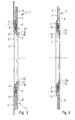
- the slide 6 In its initial position, which he when inserting the connector 1 in occupies the vacuum cleaner, there is the slide 6 in its open position (Figure 1), in the through opening 14 at the location of the connection opening 4 of the base body is arranged so that this and thus also the inlet opening 3 of the filter bag is free. From this open position can the slide 6 in a closed position ( Figure 2) are moved in which it closes the connection opening 4. In the exemplary embodiment, this movement is carried out by pulling of the slide 6 in the longitudinal direction L.
- the slide valve 6 has in its in the embodiment direction of movement coinciding with the longitudinal direction L. on the one hand the through opening 14 has a closure area 15 and on the other hand the through opening 14 one outside of the base body 5 arranged handle 16, which with the Hand can be taken. You pull the handle in Figure 1 16 to the left, the closure area 15 comes into place the connection opening 4 of the base body and closes it.
- the slide 6 can, but not necessarily, also protrude with its closure region 15 from the base body 5, and on the side of the body opposite the handle 16.
- 3 and 4 are in the cross-sectional illustration from the slide 6 only the two on both sides of the through opening 14 horizontal, web-like locking slide areas 17, 18 visible.
- the two basic material layers are 7, 8 wider than the slide 6 and on both sides of this on the side areas 12, 13 over the base body length glued together.
- the area leading the slide can at least one of the material layers by means of the slide slide on both sides attached embossing lines 21, 22 somewhat offset, d. H. be somewhat distant from the other material layer.
- the Sliding game for the slide gate could be reach in other ways. This is in the present context but of no further interest.
- the guide slot 11 is open at both ends 23, 24, d. H. the two layers of material 7, 8 are not on top of each other here glued so that the slide 6 can emerge. Possibly, when the slide gate with its handle opposite end should not protrude from the main body, you could also use the guide slot at that end close. In any case, the guide slot is open at least at the end facing the handle 16.
- the Vacuum cleaner for which the filter bag shown is intended has a fixed sealing body, one on the outside of the base body 5 of the connector 1 around the connection opening 4 circumferential contact surface is assigned, which in inserted in the vacuum cleaner state on the facing Sealing surface 25 of the sealing body arranged on the vacuum cleaner rests, so that here one around the connection opening 4 Ring seal is formed.
- the base body outside on the sealing surface 25 comes to the plant.
- connection opening 4 of the connector 1 is at the connection opening 4 of the connector 1 on this one, starting from the inner layer of material 7, in or through the perforation 10 of the outer material layer 8 projecting abutment ring 26 which is against the device side Sealing surface 25 forming contact surface 27 forms (embodiment according to Figures 1 to 3) or the contact surface 27a forming sealing part 28 holds in position (embodiment according to Figure 4).
- the bearing ring 26 thus penetrates in the open position of the slide 6, its through opening 14 and extends to the side facing away from the filter bag Outside of the connector 1 in front, so that the connection opening 4 over its axial length and thus also over the guide slot 11 is delimited all around by the bearing ring 26, which prevents dust particles from entering the guide slot 11 forms a preventive seal.
- the sealing surface 25 sealing body can be made of elastic sealing material his.
- the locking area 15 place the slide 6 over the connection opening 4.
- the base body 5 with the contact ring 26 and / or the Locking slide 6 designed so flexible that the locking slide 6 over the bearing ring 26 in its closed position can be moved.
- the slide gate deflects its otherwise occupied level of the axial dimension of the Bearing rings 26 accordingly.
- the bearing ring 26 thus forms a ring seat, so to speak extends through the outer layer of material 8 and as a sealing seat acts on the device-side sealing surface 25.
- the sealing part present in the exemplary embodiment according to FIG. 4 28 is perforated at the location of the connection opening 4 Sealing membrane 29 formed between the two layers of material 7, 8 of the base body 5 fixed, expediently is glued to the inside of the outer layer of material 8.
- This Sealing membrane 29 is ring-like in the perforation 10 of the outer Material layer 8 in front and covers the contact ring 26.
- the sealing membrane 29 consists of elastic sealing material.
- the bearing ring 26 is expediently in one piece with the inner one Material layer 7 of the base body 5 connected.
- the perforation 9 of the inner material layer 7 has a connection a smaller diameter than the perforation 10 of the outer layer of material 8 so that a radially inward over the edge of the hole 30 of the outer layer of material 8 projecting ring area of the inner layer of material 7 is formed, the in or through the Perforation 10 of the outer material layer projecting bearing ring 26 is formed is.
- the bearing ring 26 is, so to speak, from the other Level of the inner layer of material 7 slightly or the like.
- the ring area forming the abutment ring 26 can the inner layer of material 7 at the hole edge 30 of the outer layer of material 8 pressed into the perforation 10 of the outer layer of material 8 his.
- the manufacturing process can thus be as follows that with an otherwise finished connector, the hole edge 30 of the outer layer of material 8 takes, so to speak, as a shape in which the ring area of the inner material layer forming the abutment ring 26 7 presses.
Landscapes
- Engineering & Computer Science (AREA)
- Mechanical Engineering (AREA)
- Filters For Electric Vacuum Cleaners (AREA)
Claims (4)
- Raccord (1) d'un sac filtrant pour aspirateur, comportant un corps de base (5) sensiblement en forme de plaque et fixe, qui présente une couche de matière intérieure (7) tournée vers le sac et une couche de matière extérieure (8) tournée à l'opposé du sac, ces couches de matière (7, 8), notamment en carton, étant disposées l'une au-dessus de l'autre et reliées entre elles des deux côtés d'une fente de guidage (11) qui se trouve entre elles et qui est ouverte côté extrémité, fente dans laquelle est guidé un tiroir de fermeture (6) qui dépasse du corps de base (5), dans lequel le corps de base (5) présente une ouverture de raccordement (4), formée par des perforations (9, 10) alignées des couches de matière (7, 8), le tiroir de fermeture (6) présente une ouverture de passage (14), et le tiroir de fermeture (6) est déplaçable depuis une position ouverte qui libère l'ouverture de raccordement (4), dans laquelle son ouverture de passage (14) est alignée avec l'ouverture de raccordement (4), dans une position fermée qui ferme l'ouverture de raccordement (4), et dans lequel le corps de base (5) forme, sur son côté extérieur tourné à l'opposé du sac, une surface de contact (27, 27a) qui entoure l'ouverture de raccordement (4) et qui s'applique contre un corps d'étanchéité (25) de l'aspirateur, à l'état inséré dans l'aspirateur, caractérisé en ce qu'une bague de contact (26), qui part de la couche de matière intérieure (7), qui pénètre dans ou à travers la perforation (10) de la couche de matière extérieure (8) et qui forme la surface de contact (27) ou qui maintient en position un élément d'étanchéité (28) formant la surface de contact (27a), est disposée sur l'ouverture de raccordement (4), le corps de base (5) avec la bague de contact (26) et/ou le tiroir de fermeture (6) étant flexible, au point que le tiroir de fermeture (6) est déplaçable dans sa position de fermeture, au-delà de la bague de contact (26).
- Raccord selon la revendication 1, caractérisé en ce que la bague de contact (26) est reliée d'une seule pièce à la couche de matière intérieure (7) du corps de base (5), par le fait que la perforation de la couche de matière intérieure (7) présente un plus petit diamètre que la perforation (10) de la couche extérieure de matière (8), ce qui fait qu'il est formé une zone annulaire de la couche de matière intérieure (7), qui dépasse radialement vers l'intérieur du bord (30) de la perforation (10) de la couche de matière extérieure (8), et qui est formée vers la bague de contact qui s'engage dans ou à travers la perforation (10) de la couche de matière extérieure (8).
- Raccord selon la revendication 2, caractérisé en ce que la zone annulaire de la couche de matière intérieure (7), qui forme la bague de contact (26), est enfoncée sur le bord (30) de la couche de matière extérieure (8), dans la perforation (10) de la couche de matière extérieure (8).
- Raccord selon l'une des revendications 1 à 3, caractérisé en ce que l'élément d'étanchéité (28) est une membrane d'étanchéité (29) perforée, qui est fixée entre les deux couches de matière (7, 8) du corps de base (5).
Applications Claiming Priority (2)
| Application Number | Priority Date | Filing Date | Title |
|---|---|---|---|
| DE29601812U DE29601812U1 (de) | 1996-02-03 | 1996-02-03 | Anschlußstück eines Filterbeutels für Staubsauger |
| DE29601812U | 1996-02-03 |
Publications (3)
| Publication Number | Publication Date |
|---|---|
| EP0787460A2 EP0787460A2 (fr) | 1997-08-06 |
| EP0787460A3 EP0787460A3 (fr) | 1998-08-19 |
| EP0787460B1 true EP0787460B1 (fr) | 2001-07-18 |
Family
ID=8018912
Family Applications (1)
| Application Number | Title | Priority Date | Filing Date |
|---|---|---|---|
| EP96120553A Expired - Lifetime EP0787460B1 (fr) | 1996-02-03 | 1996-12-20 | Pièce de raccordement pour sac à poussière d'aspirateur |
Country Status (2)
| Country | Link |
|---|---|
| EP (1) | EP0787460B1 (fr) |
| DE (2) | DE29601812U1 (fr) |
Families Citing this family (5)
| Publication number | Priority date | Publication date | Assignee | Title |
|---|---|---|---|---|
| DE102005027078B4 (de) * | 2005-06-11 | 2007-12-13 | Jan-Robert Wulbrandt | Vorrichtung zur Befestigung von Filterbeuteln in Geräten |
| US7799107B2 (en) | 2006-03-15 | 2010-09-21 | Techtronic Floor Care Technology Limited | Self-sealing bag arrangement for a floor cleaning device |
| DE102007013279A1 (de) * | 2007-03-16 | 2008-09-25 | Gebrüder Voit GmbH | Halteplatte für Filtereinsatzbeutel, Faltzuschnitt für eine derartige Halteplatte, Filtereinsatzbeutel sowie Verfahren zum Verbinden einer Halteplatte mit einem Filtereinsatzbeutel |
| DE202007014164U1 (de) | 2007-10-01 | 2007-12-13 | Branofilter Gmbh | Filterbeutel für Staubsauger |
| CN104414570B (zh) * | 2013-08-20 | 2017-08-15 | 科沃斯机器人股份有限公司 | 自移动装置 |
Family Cites Families (4)
| Publication number | Priority date | Publication date | Assignee | Title |
|---|---|---|---|---|
| DE6909603U (de) * | 1969-03-10 | 1969-06-11 | Siemens Elektrogeraete Gmbh | Filterbefestigung fuer staubsauger. |
| EP0179950A1 (fr) * | 1984-11-01 | 1986-05-07 | Raymond Leslie Woodley | Agencement d'étanchéité |
| DE4237035A1 (de) * | 1992-11-03 | 1994-05-05 | Vorwerk Co Interholding | Staubfilterbeutel für einen Staubsauger |
| DE4315203C2 (de) * | 1993-05-07 | 1995-05-24 | Branofilter Gmbh | Filterbeutel für Staubsauger |
-
1996
- 1996-02-03 DE DE29601812U patent/DE29601812U1/de not_active Expired - Lifetime
- 1996-12-20 DE DE59607314T patent/DE59607314D1/de not_active Expired - Fee Related
- 1996-12-20 EP EP96120553A patent/EP0787460B1/fr not_active Expired - Lifetime
Also Published As
| Publication number | Publication date |
|---|---|
| DE29601812U1 (de) | 1996-03-14 |
| DE59607314D1 (de) | 2001-08-23 |
| EP0787460A3 (fr) | 1998-08-19 |
| EP0787460A2 (fr) | 1997-08-06 |
Similar Documents
| Publication | Publication Date | Title |
|---|---|---|
| EP1917897B1 (fr) | Pièce de raccordement pour un sac antipoussière ainsi que sac antipoussière doté d'une telle pièce de raccordement | |
| DE4002868C1 (en) | Vacuum cleaner filter bag - has connector made of several layers of cardboard with central opening and sliding closure | |
| EP2044874B1 (fr) | Sac filtrant pour aspirateur | |
| DE4315203C2 (de) | Filterbeutel für Staubsauger | |
| EP2046184B1 (fr) | Procede pour nettoyer le filtre d'un aspirateur et aspirateur pour mettre en oeuvre le procede | |
| DE4339298C1 (de) | Filterbeutel für Staubsauger | |
| EP1607034A1 (fr) | Sac filtrant à poussière et sa plaque adaptatrice associée | |
| DE102005017702A1 (de) | Verfahren zum Abreinigen der Filter eines Staubsaugers sowie Staubsauger zur Durchführung des Verfahrens | |
| DE3714388A1 (de) | Saugnapf | |
| DE1151905B (de) | Papierfilterbeutel fuer Staubsauger | |
| EP0873075B1 (fr) | Dispositif d'aspiration a des fins de nettoyage | |
| EP0787460B1 (fr) | Pièce de raccordement pour sac à poussière d'aspirateur | |
| DE202006017084U1 (de) | Anschlussstück für einen Staubfilterbeutel sowie mit einem solchen Anschlussstück ausgestatteter Staubfilterbeutel | |
| DE202004008972U1 (de) | Staubfilterbeutel | |
| EP1627589B1 (fr) | Appareil d'aspiration, notamment pour poussière | |
| DE102019102357B4 (de) | Vorrichtung zur Absperrung oder Steuerung des Durchflusses von schmutzbeladener Luft, Reinigungsgerät und Behältnis zum Abtrennen und/oder Sammeln von Schmutz mit einer solchen Vorrichtung | |
| DE102006029059A1 (de) | Filtereinrichtung für Staubsauger und Verfahren zur Herstellung der Filtereinrichtung | |
| DE202004008971U1 (de) | Staubfilterbeutel | |
| DE202007014163U1 (de) | Filterbeutel für einen Staubsauger | |
| DE19608798A1 (de) | Tastventil | |
| DE102017123660A1 (de) | Staubsauger und Umschaltventil zum Umschalten von Luftströmen für einen Staubsauger | |
| DE4429342A1 (de) | Anschlußstück eines Filterbeutels für Staubsauger | |
| DE4221700C2 (de) | Anschlußstück eines Filtersacks für staubabsaugende Geräte | |
| DE202011000084U1 (de) | Evakuierbares Aufbewahrungsbehältnis | |
| WO2020011828A1 (fr) | Dispositif de réception de particules, ensemble et procédé pour faire fonctionner un ensemble |
Legal Events
| Date | Code | Title | Description |
|---|---|---|---|
| PUAI | Public reference made under article 153(3) epc to a published international application that has entered the european phase |
Free format text: ORIGINAL CODE: 0009012 |
|
| AK | Designated contracting states |
Kind code of ref document: A2 Designated state(s): BE DE FR GB IT NL SE |
|
| PUAL | Search report despatched |
Free format text: ORIGINAL CODE: 0009013 |
|
| AK | Designated contracting states |
Kind code of ref document: A3 Designated state(s): BE DE FR GB IT NL SE |
|
| 17P | Request for examination filed |
Effective date: 19980720 |
|
| 17Q | First examination report despatched |
Effective date: 19991007 |
|
| GRAG | Despatch of communication of intention to grant |
Free format text: ORIGINAL CODE: EPIDOS AGRA |
|
| GRAG | Despatch of communication of intention to grant |
Free format text: ORIGINAL CODE: EPIDOS AGRA |
|
| GRAH | Despatch of communication of intention to grant a patent |
Free format text: ORIGINAL CODE: EPIDOS IGRA |
|
| GRAH | Despatch of communication of intention to grant a patent |
Free format text: ORIGINAL CODE: EPIDOS IGRA |
|
| GRAA | (expected) grant |
Free format text: ORIGINAL CODE: 0009210 |
|
| AK | Designated contracting states |
Kind code of ref document: B1 Designated state(s): BE DE FR GB IT NL SE |
|
| GBT | Gb: translation of ep patent filed (gb section 77(6)(a)/1977) |
Effective date: 20010718 |
|
| REF | Corresponds to: |
Ref document number: 59607314 Country of ref document: DE Date of ref document: 20010823 |
|
| ET | Fr: translation filed | ||
| REG | Reference to a national code |
Ref country code: GB Ref legal event code: IF02 |
|
| PLBE | No opposition filed within time limit |
Free format text: ORIGINAL CODE: 0009261 |
|
| STAA | Information on the status of an ep patent application or granted ep patent |
Free format text: STATUS: NO OPPOSITION FILED WITHIN TIME LIMIT |
|
| 26N | No opposition filed | ||
| PGFP | Annual fee paid to national office [announced via postgrant information from national office to epo] |
Ref country code: BE Payment date: 20051031 Year of fee payment: 10 |
|
| PGFP | Annual fee paid to national office [announced via postgrant information from national office to epo] |
Ref country code: DE Payment date: 20051122 Year of fee payment: 10 |
|
| PGFP | Annual fee paid to national office [announced via postgrant information from national office to epo] |
Ref country code: GB Payment date: 20051201 Year of fee payment: 10 |
|
| PGFP | Annual fee paid to national office [announced via postgrant information from national office to epo] |
Ref country code: SE Payment date: 20051207 Year of fee payment: 10 |
|
| PGFP | Annual fee paid to national office [announced via postgrant information from national office to epo] |
Ref country code: NL Payment date: 20051219 Year of fee payment: 10 |
|
| PGFP | Annual fee paid to national office [announced via postgrant information from national office to epo] |
Ref country code: FR Payment date: 20051220 Year of fee payment: 10 |
|
| PG25 | Lapsed in a contracting state [announced via postgrant information from national office to epo] |
Ref country code: SE Free format text: LAPSE BECAUSE OF NON-PAYMENT OF DUE FEES Effective date: 20061221 |
|
| PG25 | Lapsed in a contracting state [announced via postgrant information from national office to epo] |
Ref country code: BE Free format text: LAPSE BECAUSE OF NON-PAYMENT OF DUE FEES Effective date: 20061231 |
|
| PGFP | Annual fee paid to national office [announced via postgrant information from national office to epo] |
Ref country code: IT Payment date: 20061231 Year of fee payment: 11 |
|
| PG25 | Lapsed in a contracting state [announced via postgrant information from national office to epo] |
Ref country code: NL Free format text: LAPSE BECAUSE OF NON-PAYMENT OF DUE FEES Effective date: 20070701 |
|
| PG25 | Lapsed in a contracting state [announced via postgrant information from national office to epo] |
Ref country code: DE Free format text: LAPSE BECAUSE OF NON-PAYMENT OF DUE FEES Effective date: 20070703 |
|
| EUG | Se: european patent has lapsed | ||
| GBPC | Gb: european patent ceased through non-payment of renewal fee |
Effective date: 20061220 |
|
| NLV4 | Nl: lapsed or anulled due to non-payment of the annual fee |
Effective date: 20070701 |
|
| REG | Reference to a national code |
Ref country code: FR Ref legal event code: ST Effective date: 20070831 |
|
| PG25 | Lapsed in a contracting state [announced via postgrant information from national office to epo] |
Ref country code: GB Free format text: LAPSE BECAUSE OF NON-PAYMENT OF DUE FEES Effective date: 20061220 |
|
| BERE | Be: lapsed |
Owner name: *BRANOFILTER G.M.B.H. Effective date: 20061231 |
|
| PG25 | Lapsed in a contracting state [announced via postgrant information from national office to epo] |
Ref country code: FR Free format text: LAPSE BECAUSE OF NON-PAYMENT OF DUE FEES Effective date: 20070102 |
|
| PG25 | Lapsed in a contracting state [announced via postgrant information from national office to epo] |
Ref country code: IT Free format text: LAPSE BECAUSE OF NON-PAYMENT OF DUE FEES Effective date: 20071220 |