EP0786363B1 - Configuration des conduits d'air pour l'aération ou le chauffage du fond d'un véhicule automobile - Google Patents
Configuration des conduits d'air pour l'aération ou le chauffage du fond d'un véhicule automobile Download PDFInfo
- Publication number
- EP0786363B1 EP0786363B1 EP97100163A EP97100163A EP0786363B1 EP 0786363 B1 EP0786363 B1 EP 0786363B1 EP 97100163 A EP97100163 A EP 97100163A EP 97100163 A EP97100163 A EP 97100163A EP 0786363 B1 EP0786363 B1 EP 0786363B1
- Authority
- EP
- European Patent Office
- Prior art keywords
- air
- air duct
- arrangement according
- duct arrangement
- opening
- Prior art date
- Legal status (The legal status is an assumption and is not a legal conclusion. Google has not performed a legal analysis and makes no representation as to the accuracy of the status listed.)
- Expired - Lifetime
Links
Images


Classifications
-
- B—PERFORMING OPERATIONS; TRANSPORTING
- B60—VEHICLES IN GENERAL
- B60H—ARRANGEMENTS OF HEATING, COOLING, VENTILATING OR OTHER AIR-TREATING DEVICES SPECIALLY ADAPTED FOR PASSENGER OR GOODS SPACES OF VEHICLES
- B60H1/00—Heating, cooling or ventilating [HVAC] devices
- B60H1/24—Devices purely for ventilating or where the heating or cooling is irrelevant
- B60H1/241—Devices purely for ventilating or where the heating or cooling is irrelevant characterised by the location of ventilation devices in the vehicle
- B60H1/246—Devices purely for ventilating or where the heating or cooling is irrelevant characterised by the location of ventilation devices in the vehicle located in the interior of the vehicle or in or below the floor
-
- B—PERFORMING OPERATIONS; TRANSPORTING
- B60—VEHICLES IN GENERAL
- B60H—ARRANGEMENTS OF HEATING, COOLING, VENTILATING OR OTHER AIR-TREATING DEVICES SPECIALLY ADAPTED FOR PASSENGER OR GOODS SPACES OF VEHICLES
- B60H1/00—Heating, cooling or ventilating [HVAC] devices
- B60H1/24—Devices purely for ventilating or where the heating or cooling is irrelevant
- B60H1/247—Disposition of several air-diffusers in a vehicle for ventilation-air circulation in a vehicle cabin
Definitions
- the invention relates to an air duct arrangement for rear ventilation and / or heating a motor vehicle, especially a passenger car.
- Heating and / or air conditioning systems for the interior of motor vehicles, also in the rear room Air outlet openings are known.
- EP-0 458 705-A2 describes a car ventilation and heating system with one Ventilation and heating device with a distribution device, each for the front and Side windows, the foot area and the interior separate exits or connections has, with a connection for an air duct being provided for the rear area divides into two subchannels at a distance from the connection area, each one Rear side equally ventilated or heated.
- EP-0 170 177-A1 and EP-0 210 548-A2 each describe a heating and Air conditioning for the interior of passenger cars, including the rear compartment driver's side and the rear passenger side by separately arranged Air ducts are connected to the heating and air conditioning unit.
- a comparable solution is known from EP-0 059 424-A2.
- DE-30 43 548-C2 describes separately from each other adjustable air outlet devices in the area of the dashboard Motor vehicle are arranged and one of which is provided for the rear, on the an air duct that extends in a fork-shaped manner to the two rear sides over a Connection is connected, which ventilates both sides of the fund and equally heated.
- the object of the invention is to provide an air duct arrangement for rear ventilation and / or to provide heating for a motor vehicle, in particular a passenger car, with which the two fund sides can be ventilated and / or heated differently and in which the construction and assembly work is reduced.
- the measure according to claim 2 prevents air passage in a simple manner between the air inlet ports of the two rear side channels.
- the ventilation and / or heater side fixation of the air duct arrangement is advantageously carried out by a each of the two rear side channels arranged locking and fixing bolt with a mounting element arranged on the vehicle tunnel can be brought into engagement.
- the two bolts is also the predetermined mutual location assignment and arrangement the air inlet nozzle in the connection nozzle is defined.
- each with a hold freedom have a locking projection for engaging in a seat cross member recess and
- Haltedom represents a fixed camp for the respective fund side channel Rear side channels screwlessly attached to the vehicle body in a predetermined manner become.
- the insertion point of the connector in the connector can be easily airtight thanks to a flexible bellows hose or a spout are enclosed so that the ventilation and / or heater to the air duct arrangement controlled air flows flow into the rear side channels without loss.
- the rear side channels can be in the area of the respective front footwell on the side facing away from the tunnel have an opening for ventilation and / or Heating the relevant footwell can be used.
- the opening of the rear side channel running on the passenger side as ventilation and / or to use the heating opening and that of the one running on the driver's side Cover the rear side channel through the vehicle carpet or the damping covering.
- the opening of each rear side channel through the vehicle carpet arranged on the driver's side or the damping covering are covered.
- the measure according to claim 8 is used in a simple way a defined air flow at the ventilation opening.
- claim 9 can be arranged according to claim 8 aperture in a simple manner a spreading clip on the respective fund side channel by attaching to this in a hole is arranged in the area of the opening of the tunnel-side wall, the Border is issued in the channel in which the spreading clip locked on the panel is pressed and engages behind the hole, while covering the panel with the vehicle carpet fixed to the fund side channel.
- the panel can be provided with adjustable ventilation slats according to claim 10 that the ventilation and / or heater side for the rear side channel with regard to temperature and air flow regulated air flow in addition to its outlet direction can be changed.
- the forked air duct for the vehicle rear divided into the two rear side ducts advantageously consists of polypropylene or polyethylene, which is its manufacture simplified by the locking and fixing bolts according to claim 3, but also the Dome according to claim 4 can be attached to the blow molding.
- Fig. 1 is an air duct arrangement according to the invention made of polypropylene for the rear ventilation and / or heating a passenger car shown. It has an air inlet side Connector 1 for a connecting piece (not shown) one Ventilation and / or heater, two of which are fork-shaped on the rear side Extend fund side channels 2 and 3 on both fund sides. These fund side channels 2 and 3 are on both sides of the vehicle tunnel (not shown), on this adjacent, led to the rear footwell and have an air outlet at the end 4 and 5.
- connection piece 1 is made of the air inlet connections 6 and 7 on the ventilation unit side educated. These are aligned parallel to each other and each have a counter-soapy Attachable wall 8 and 9 on that facing away from the vehicle tunnel Side are connected by a film hinge 10, the extent of which here does not quite reach the front edges of the air inlet connection.
- This franking enables the formation of partially circumferential locking beads 6a and 7a with which a bellows to be pushed on and preferably held on the connecting piece can be locked.
- the rear side channels 2, 3 achieved a better sealing effect.
- the air inlet nozzle 6 and 7 In the walls 8 and 9 is at a short distance from the air inlet opening perpendicular to the longitudinal axis the air inlet nozzle 6 and 7 and trained to the right side of the vehicle preferably bulge-like bulge 11 or 12 for mutual Intervention arranged (Fig. 2 and 3).
- the fund side channels 2, 3 secured against axial displacement. It also becomes one Labyrinth seal creates the air passage between the walls 8, 9 almost completely prevented.
- On both rear side channels 2 and 3 is below their air inlet connection 6 and 7 each have a locking and fixing bolt in the direction of their longitudinal axis 13 and 14 for engaging in a tunnel-fixed mounting element (not shown) educated.
- Both fund side channels 2 and 3 point in the fund end area
- Seat cross member 19 in which a corresponding recess is present (Fig. 4).
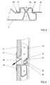
- Both rear side channels 2 and 3 are facing the front footwell Wall an opening 20 and 21 and in the facing the tunnel Wall 22 and 23 in the area of the respective opening 20, 21, a hole 24 and 25 respectively arranged, the border 26 and 27 in the interior of the respective rear side channel 2 or 3 is issued.
- the assembly is carried out in such a way that the two through the film hinge 10 together connected air inlet nozzle 6, 7 of the rear side channels 2, 3 with their walls 8, 9 merged and then in the (not shown) connecting piece of the ventilation and / or heater are introduced, with the locking and fixing bolts 13 and 14 in the tunnel-fixed mounting element (not shown) intervention. Then the fund-side end areas of the two fund-side channels 2 and 3 fixed to the vehicle body by the arranged on these Holding domes 15 and 16 pressed into the respective seat cross member 19 and there by the on the retaining domes 15, 16 arranged locking projections 17 and 18 are fixed. This means that the air duct with its two rear side ducts 2 and 3 is screwless, however firmly arranged on the vehicle body.
- the Opening 20 covers, while opening 21 through a corresponding recess in the cushioning surface D for ventilation and / or heating of the passenger footwell remains uncovered.
- this opening 21 there is a diaphragm over the damping coating D. 28 arranged, which can be fixed with an expansion clip 29 in the hole 25 by this issued border 27 of the hole engages behind.
- the inside of the rear side channel 3 located side wall 31 of the panel 28 is to the tunnel-side wall 23 angled towards to allow air outlet.
- the bezel 28 also instructs on its side facing the footwell, two reaching into the rear side channel 3, air guiding blades arranged at a distance behind one another - if necessary also adjustable 30 on the exiting air flow in a predetermined direction of exit to steer.
Claims (11)
- Configuration des conduits d'air pour l'aération et/ou le chauffage de l'arrière comprenant une pièce de connexion (1) du côté de l'entrée d'air pour une tubulure de connexion d'un appareil d'aération et/ou de chauffage et deux conduits pour les côtés arrière (2 et 3) partant, du côté arrière, depuis la pièce de connexion (1), et s'étendant en forme de fourche de chaque côté du tunnel du véhicule vers les deux côtés arrière, avec à chaque fois une ouverture de sortie d'air (5) du côté de l'extrémité, caractérisée en ce que la pièce de connexion (1) est formée par des tubulures d'entrée d'air (6 et 7) des deux conduits pour les côtés arrière (2 et 3) du côté de l'appareil d'aération et/ou de chauffage, qui sont orientées essentiellement parallèlement l'une à l'autre et présentent à chaque fois au moins une paroi (8, 9) pouvant s'appliquer l'une contre l'autre, et en ce que les tubulures d'entrée d'air (6, 7) sont connectées l'une à l'autre sur leur côté opposé au tunnel du véhicule le long des parois (8, 9) par au moins une charnière à film (10).
- Configuration des conduits d'air selon la revendication 1, caractérisée en ce que les parois (8) et (9) présentent, à une faible distance de l'ouverture d'entrée d'air respective, à chaque fois une convexité (11, 12) en forme de moulure disposée essentiellement perpendiculairement par rapport à l'axe longitudinal de la tubulure d'entrée d'air (6, 7), en vue d'un engagement mutuel.
- Configuration des conduits d'air selon la revendication 1 ou 2, caractérisée en ce que les conduits pour les côtés arrière (2, 3) présentent, sous les tubulures d'entrée d'air (6, 7), un boulon de blocage et de fixation (13, 14) pour l'engagement dans un élément de fixation fixé au tunnel.
- Configuration des conduits d'air selon la revendication 1, 2 ou 3, caractérisée en ce que les conduits pour les côtés arrière (2, 3) présentent, dans la région de l'extrémité du côté arrière, du côté du fond du véhicule, à chaque fois un dôme de fixation (15, 16) avec une saillie d'encliquetage (17, 18) pour l'engagement dans un logement d'une glissière de siège.
- Configuration des conduits d'air selon la revendication 1 ou l'une quelconque des revendications subséquentes, caractérisée en ce que la région d'enfoncement de la pièce de connexion (1) dans les tubulures de connexion est entourée par un boyau plissé souple.
- Configuration des conduits d'air selon la revendication 1 ou l'une quelconque des revendications subséquentes, caractérisée en ce que les conduits pour les côtés arrière (2, 3) présentent, dans la région de l'espace avant pour les pieds, dans leur paroi opposée au tunnel, une ouverture (20, 21).
- Configuration des conduits d'air selon la revendication 6, caractérisée en ce que l'ouverture (20, 21) du conduit respectif pour le côté arrière (2 ou 3) s'étendant du côté du passager peut être utilisée en tant qu'ouverture d'aération, et celle du conduit pour le côté arrière (3 ou 2) s'étendant du côté du conducteur peut être recouverte par la garniture d'atténuation (D).
- Configuration des conduits d'air selon la revendication 6 ou 7, caractérisée en ce que l'ouverture d'aération (20, 21) débouche à travers un évidement dans la garniture d'atténuation (D) dans l'espace pour les pieds, et est pourvue d'un diaphragme (28) pouvant être inséré et fixé du côté de l'atténuation, avec des lamelles de guidage de l'air (30) atteignant le conduit pour le côté arrière (2, 3).
- Configuration des conduits d'air selon la revendication 8, caractérisée en ce que le diaphragme (28) peut être fixé avec un clip d'écartement (29) dans un trou (24, 25) disposé dans la paroi (22, 23) du côté du tunnel du conduit respectif pour le côté arrière (2, 3) en face de l'ouverture (20, 21), avec une exposition de la périphérie du trou du côté du conduit pour le côté arrière (2, 3).
- Configuration des conduits d'air selon la revendication 8, caractérisée en ce que les lamelles de guidage d'air (30) sont ajustables.
- Configuration des conduits d'air selon la revendication 1 ou l'une ou plusieurs des revendications subséquentes, caractérisée en ce que les conduits pour les côtés arrière (2, 3) sont fabriqués en propylène ou en polyéthylène.
Applications Claiming Priority (2)
| Application Number | Priority Date | Filing Date | Title |
|---|---|---|---|
| DE19602956 | 1996-01-27 | ||
| DE19602956 | 1996-01-27 |
Publications (3)
| Publication Number | Publication Date |
|---|---|
| EP0786363A2 EP0786363A2 (fr) | 1997-07-30 |
| EP0786363A3 EP0786363A3 (fr) | 1999-06-16 |
| EP0786363B1 true EP0786363B1 (fr) | 2002-05-29 |
Family
ID=7783874
Family Applications (1)
| Application Number | Title | Priority Date | Filing Date |
|---|---|---|---|
| EP97100163A Expired - Lifetime EP0786363B1 (fr) | 1996-01-27 | 1997-01-08 | Configuration des conduits d'air pour l'aération ou le chauffage du fond d'un véhicule automobile |
Country Status (2)
| Country | Link |
|---|---|
| EP (1) | EP0786363B1 (fr) |
| DE (1) | DE59707343D1 (fr) |
Families Citing this family (8)
| Publication number | Priority date | Publication date | Assignee | Title |
|---|---|---|---|---|
| JP2003034115A (ja) * | 2001-07-23 | 2003-02-04 | Mitsubishi Heavy Ind Ltd | 自動車用空調ダクト |
| FR2836659B1 (fr) * | 2002-03-01 | 2004-05-28 | Renault | Grille d'aeration d'habitacle de vehicule automobile prevue pour etre montee sur un plancher de vehicule automobile |
| FR2871101A1 (fr) * | 2004-06-02 | 2005-12-09 | Renault Sas | Dispositif d'habillage pour un habitacle de vehicule automobile |
| DE102005011832B4 (de) * | 2005-03-15 | 2011-01-20 | Audi Ag | Luftführungseinrichtung für ein Fahrzeug |
| DE102009008274A1 (de) * | 2009-02-10 | 2010-08-12 | GM Global Technology Operations, Inc., Detroit | Ablaufschlauchsystem für eine Kraftfahrzeug-Klimaanlage |
| DE102012106402A1 (de) | 2012-07-17 | 2014-05-15 | Dr. Ing. H.C. F. Porsche Aktiengesellschaft | Kraftfahrzeug mit einem einteilig ausgestalteten Luftführungskanal |
| JP7295049B2 (ja) * | 2020-01-30 | 2023-06-20 | トヨタ自動車株式会社 | 車両構造 |
| EP3964372A1 (fr) * | 2020-09-03 | 2022-03-09 | TI Automotive Technology Center GmbH | Agencement de conduites pour le transport des milieux de mise à la température |
Family Cites Families (10)
| Publication number | Priority date | Publication date | Assignee | Title |
|---|---|---|---|---|
| US2882809A (en) * | 1957-09-17 | 1959-04-21 | Glenn J Nelson | Air duct for motor vehicles |
| US4191242A (en) * | 1977-03-28 | 1980-03-04 | Mitsubishi Jidosha Kogyo Kabushiki Kaisha | Air conditioner operating apparatus |
| JPS5674551A (en) | 1979-11-20 | 1981-06-20 | Nissan Motor Co Ltd | Fluid blowing-off structure |
| JPS57144116A (en) | 1981-02-27 | 1982-09-06 | Nissan Motor Co Ltd | Room heater for vehicle |
| JPS59186117U (ja) * | 1983-05-31 | 1984-12-11 | 日産車体株式会社 | 自動車用空調装置 |
| DE3427292A1 (de) | 1984-07-24 | 1986-01-30 | Bayerische Motoren Werke AG, 8000 München | Heiz- und klimaanlage in kraftfahrzeugen |
| EP0210548B2 (fr) | 1985-07-20 | 1994-05-04 | Bayerische Motoren Werke Aktiengesellschaft, Patentabteilung AJ-3 | Installation de chauffage et/ou de climatisation pour l'habitacle de véhicules à moteur, en particulier pour voitures |
| DE3909813A1 (de) * | 1989-03-24 | 1990-09-27 | Vogelsang Ernst Gmbh Co Kg | Kabelfuehrungsrohrbuendel aus einer mehrzahl von kunststoffrohren |
| DE3940361A1 (de) * | 1989-12-06 | 1991-06-13 | Bayerische Motoren Werke Ag | Heizungs- und/oder klimaanlage fuer kraftfahrzeuginnenraeume |
| JP2566044B2 (ja) | 1990-05-25 | 1996-12-25 | 日産自動車株式会社 | 車両用空気調和装置のヒータユニット構造 |
-
1997
- 1997-01-08 EP EP97100163A patent/EP0786363B1/fr not_active Expired - Lifetime
- 1997-01-08 DE DE59707343T patent/DE59707343D1/de not_active Expired - Lifetime
Also Published As
| Publication number | Publication date |
|---|---|
| DE59707343D1 (de) | 2002-07-04 |
| EP0786363A2 (fr) | 1997-07-30 |
| EP0786363A3 (fr) | 1999-06-16 |
Similar Documents
| Publication | Publication Date | Title |
|---|---|---|
| DE2813909C2 (de) | Instrumententafel für Kraftfahrzeuge | |
| DE3529940C3 (de) | Heiz- und Klimagerät für Kraftfahrzeuge | |
| DE3447185C2 (fr) | ||
| DE19731908B4 (de) | Heizungs- und Klimaanlage für ein Kraftfahrzeug | |
| DE60225979T2 (de) | Vorrichtung zur Erzeugung einer temperaturgeregelten Luftströmung für einen Kraftfahrzeugfahrgastraum und Heizungs- und/oder Klimaanlage mit einer solchen Sicherungsvorrichtung | |
| DE10037384B4 (de) | Heizungs- und Klimaanlage für ein Kraftfahrzeug | |
| EP1560723A1 (fr) | Dispositif et procede de repartition d'air dans un vehicule | |
| EP0200899B1 (fr) | Dispositif pour la ventilation et la climatisation des postes ou cabines de conducteur | |
| EP0663309B1 (fr) | Dispositif de chauffage ou de climatisation, en particulier pour l'installation dans un véhicule automobile | |
| EP0786363B1 (fr) | Configuration des conduits d'air pour l'aération ou le chauffage du fond d'un véhicule automobile | |
| DE10242805A1 (de) | Belüftungseinrichtung für ein Kraftfahrzeug | |
| DE19804287C1 (de) | Klimaanlage für Fahrzeuge | |
| DE102009044760B4 (de) | Klimaanlage für ein Kraftfahrzeug | |
| DE3608524A1 (de) | Heiz- und belueftungseinrichtung | |
| EP1228907B1 (fr) | Appareil de climatisation pour véhicule automobile | |
| DE4243165A1 (de) | Klimagerät für ein Kraftfahrzeug | |
| DE102007029635A1 (de) | Vorrichtung zur Kühlung von Elektronikbauteilen | |
| DE10062151B4 (de) | Instrumententafel, insbesondere für ein Kraftfahrzeug, mit einem Grundkörper und einer Abdeckung | |
| DE102007049340A1 (de) | Kraftfahrzeug-Klimaanlagenanordnung | |
| DE19540020A1 (de) | Baueinheit für ein Kraftfahrzeug | |
| DE10042683A1 (de) | Klimatisierungsbaueinheit | |
| DE19742566C1 (de) | Vorrichtung zur Luftverteilung in einem Fahrzeuginnenraum | |
| DE102018121528A1 (de) | Heiz-/Klimagerät für ein Kraftfahrzeug | |
| DE102008013450A1 (de) | Fahrgastklimatisierung in einem Fahrzeug | |
| DE19816330C1 (de) | Heizungs- oder Klimaanlage |
Legal Events
| Date | Code | Title | Description |
|---|---|---|---|
| PUAI | Public reference made under article 153(3) epc to a published international application that has entered the european phase |
Free format text: ORIGINAL CODE: 0009012 |
|
| AK | Designated contracting states |
Kind code of ref document: A2 Designated state(s): DE FR GB IT |
|
| PUAL | Search report despatched |
Free format text: ORIGINAL CODE: 0009013 |
|
| AK | Designated contracting states |
Kind code of ref document: A3 Designated state(s): DE FR GB IT |
|
| 17P | Request for examination filed |
Effective date: 19991216 |
|
| RTI1 | Title (correction) |
Free format text: AIR DUCT ARRANGEMENT FOR THE AERATION OR HEATING OF THE REAR PASSENGER COMPARTIMENT OF A VEHICLE |
|
| GRAG | Despatch of communication of intention to grant |
Free format text: ORIGINAL CODE: EPIDOS AGRA |
|
| 17Q | First examination report despatched |
Effective date: 20010605 |
|
| GRAG | Despatch of communication of intention to grant |
Free format text: ORIGINAL CODE: EPIDOS AGRA |
|
| GRAH | Despatch of communication of intention to grant a patent |
Free format text: ORIGINAL CODE: EPIDOS IGRA |
|
| GRAH | Despatch of communication of intention to grant a patent |
Free format text: ORIGINAL CODE: EPIDOS IGRA |
|
| GRAA | (expected) grant |
Free format text: ORIGINAL CODE: 0009210 |
|
| AK | Designated contracting states |
Kind code of ref document: B1 Designated state(s): DE FR GB IT |
|
| REG | Reference to a national code |
Ref country code: GB Ref legal event code: FG4D Free format text: NOT ENGLISH |
|
| REF | Corresponds to: |
Ref document number: 59707343 Country of ref document: DE Date of ref document: 20020704 |
|
| GBT | Gb: translation of ep patent filed (gb section 77(6)(a)/1977) |
Effective date: 20020729 |
|
| ET | Fr: translation filed | ||
| PLBE | No opposition filed within time limit |
Free format text: ORIGINAL CODE: 0009261 |
|
| STAA | Information on the status of an ep patent application or granted ep patent |
Free format text: STATUS: NO OPPOSITION FILED WITHIN TIME LIMIT |
|
| 26N | No opposition filed |
Effective date: 20030303 |
|
| PGFP | Annual fee paid to national office [announced via postgrant information from national office to epo] |
Ref country code: DE Payment date: 20110131 Year of fee payment: 15 |
|
| PGFP | Annual fee paid to national office [announced via postgrant information from national office to epo] |
Ref country code: GB Payment date: 20120131 Year of fee payment: 16 Ref country code: IT Payment date: 20120125 Year of fee payment: 16 |
|
| PG25 | Lapsed in a contracting state [announced via postgrant information from national office to epo] |
Ref country code: DE Free format text: LAPSE BECAUSE OF NON-PAYMENT OF DUE FEES Effective date: 20120801 |
|
| REG | Reference to a national code |
Ref country code: DE Ref legal event code: R119 Ref document number: 59707343 Country of ref document: DE Effective date: 20120801 |
|
| PGFP | Annual fee paid to national office [announced via postgrant information from national office to epo] |
Ref country code: FR Payment date: 20130219 Year of fee payment: 17 |
|
| GBPC | Gb: european patent ceased through non-payment of renewal fee |
Effective date: 20130108 |
|
| PG25 | Lapsed in a contracting state [announced via postgrant information from national office to epo] |
Ref country code: GB Free format text: LAPSE BECAUSE OF NON-PAYMENT OF DUE FEES Effective date: 20130108 |
|
| PG25 | Lapsed in a contracting state [announced via postgrant information from national office to epo] |
Ref country code: IT Free format text: LAPSE BECAUSE OF NON-PAYMENT OF DUE FEES Effective date: 20130108 |
|
| REG | Reference to a national code |
Ref country code: FR Ref legal event code: ST Effective date: 20140930 |
|
| PG25 | Lapsed in a contracting state [announced via postgrant information from national office to epo] |
Ref country code: FR Free format text: LAPSE BECAUSE OF NON-PAYMENT OF DUE FEES Effective date: 20140131 |