EP0786363B1 - Air duct arrangement for the aeration or heating of the rear passenger compartiment of a vehicle - Google Patents
Air duct arrangement for the aeration or heating of the rear passenger compartiment of a vehicle Download PDFInfo
- Publication number
- EP0786363B1 EP0786363B1 EP97100163A EP97100163A EP0786363B1 EP 0786363 B1 EP0786363 B1 EP 0786363B1 EP 97100163 A EP97100163 A EP 97100163A EP 97100163 A EP97100163 A EP 97100163A EP 0786363 B1 EP0786363 B1 EP 0786363B1
- Authority
- EP
- European Patent Office
- Prior art keywords
- air
- air duct
- arrangement according
- duct arrangement
- opening
- Prior art date
- Legal status (The legal status is an assumption and is not a legal conclusion. Google has not performed a legal analysis and makes no representation as to the accuracy of the status listed.)
- Expired - Lifetime
Links
Images


Classifications
-
- B—PERFORMING OPERATIONS; TRANSPORTING
- B60—VEHICLES IN GENERAL
- B60H—ARRANGEMENTS OF HEATING, COOLING, VENTILATING OR OTHER AIR-TREATING DEVICES SPECIALLY ADAPTED FOR PASSENGER OR GOODS SPACES OF VEHICLES
- B60H1/00—Heating, cooling or ventilating [HVAC] devices
- B60H1/24—Devices purely for ventilating or where the heating or cooling is irrelevant
- B60H1/241—Devices purely for ventilating or where the heating or cooling is irrelevant characterised by the location of ventilation devices in the vehicle
- B60H1/246—Devices purely for ventilating or where the heating or cooling is irrelevant characterised by the location of ventilation devices in the vehicle located in the interior of the vehicle or in or below the floor
-
- B—PERFORMING OPERATIONS; TRANSPORTING
- B60—VEHICLES IN GENERAL
- B60H—ARRANGEMENTS OF HEATING, COOLING, VENTILATING OR OTHER AIR-TREATING DEVICES SPECIALLY ADAPTED FOR PASSENGER OR GOODS SPACES OF VEHICLES
- B60H1/00—Heating, cooling or ventilating [HVAC] devices
- B60H1/24—Devices purely for ventilating or where the heating or cooling is irrelevant
- B60H1/247—Disposition of several air-diffusers in a vehicle for ventilation-air circulation in a vehicle cabin
Definitions
- the invention relates to an air duct arrangement for rear ventilation and / or heating a motor vehicle, especially a passenger car.
- Heating and / or air conditioning systems for the interior of motor vehicles, also in the rear room Air outlet openings are known.
- EP-0 458 705-A2 describes a car ventilation and heating system with one Ventilation and heating device with a distribution device, each for the front and Side windows, the foot area and the interior separate exits or connections has, with a connection for an air duct being provided for the rear area divides into two subchannels at a distance from the connection area, each one Rear side equally ventilated or heated.
- EP-0 170 177-A1 and EP-0 210 548-A2 each describe a heating and Air conditioning for the interior of passenger cars, including the rear compartment driver's side and the rear passenger side by separately arranged Air ducts are connected to the heating and air conditioning unit.
- a comparable solution is known from EP-0 059 424-A2.
- DE-30 43 548-C2 describes separately from each other adjustable air outlet devices in the area of the dashboard Motor vehicle are arranged and one of which is provided for the rear, on the an air duct that extends in a fork-shaped manner to the two rear sides over a Connection is connected, which ventilates both sides of the fund and equally heated.
- the object of the invention is to provide an air duct arrangement for rear ventilation and / or to provide heating for a motor vehicle, in particular a passenger car, with which the two fund sides can be ventilated and / or heated differently and in which the construction and assembly work is reduced.
- the measure according to claim 2 prevents air passage in a simple manner between the air inlet ports of the two rear side channels.
- the ventilation and / or heater side fixation of the air duct arrangement is advantageously carried out by a each of the two rear side channels arranged locking and fixing bolt with a mounting element arranged on the vehicle tunnel can be brought into engagement.
- the two bolts is also the predetermined mutual location assignment and arrangement the air inlet nozzle in the connection nozzle is defined.
- each with a hold freedom have a locking projection for engaging in a seat cross member recess and
- Haltedom represents a fixed camp for the respective fund side channel Rear side channels screwlessly attached to the vehicle body in a predetermined manner become.
- the insertion point of the connector in the connector can be easily airtight thanks to a flexible bellows hose or a spout are enclosed so that the ventilation and / or heater to the air duct arrangement controlled air flows flow into the rear side channels without loss.
- the rear side channels can be in the area of the respective front footwell on the side facing away from the tunnel have an opening for ventilation and / or Heating the relevant footwell can be used.
- the opening of the rear side channel running on the passenger side as ventilation and / or to use the heating opening and that of the one running on the driver's side Cover the rear side channel through the vehicle carpet or the damping covering.
- the opening of each rear side channel through the vehicle carpet arranged on the driver's side or the damping covering are covered.
- the measure according to claim 8 is used in a simple way a defined air flow at the ventilation opening.
- claim 9 can be arranged according to claim 8 aperture in a simple manner a spreading clip on the respective fund side channel by attaching to this in a hole is arranged in the area of the opening of the tunnel-side wall, the Border is issued in the channel in which the spreading clip locked on the panel is pressed and engages behind the hole, while covering the panel with the vehicle carpet fixed to the fund side channel.
- the panel can be provided with adjustable ventilation slats according to claim 10 that the ventilation and / or heater side for the rear side channel with regard to temperature and air flow regulated air flow in addition to its outlet direction can be changed.
- the forked air duct for the vehicle rear divided into the two rear side ducts advantageously consists of polypropylene or polyethylene, which is its manufacture simplified by the locking and fixing bolts according to claim 3, but also the Dome according to claim 4 can be attached to the blow molding.
- Fig. 1 is an air duct arrangement according to the invention made of polypropylene for the rear ventilation and / or heating a passenger car shown. It has an air inlet side Connector 1 for a connecting piece (not shown) one Ventilation and / or heater, two of which are fork-shaped on the rear side Extend fund side channels 2 and 3 on both fund sides. These fund side channels 2 and 3 are on both sides of the vehicle tunnel (not shown), on this adjacent, led to the rear footwell and have an air outlet at the end 4 and 5.
- connection piece 1 is made of the air inlet connections 6 and 7 on the ventilation unit side educated. These are aligned parallel to each other and each have a counter-soapy Attachable wall 8 and 9 on that facing away from the vehicle tunnel Side are connected by a film hinge 10, the extent of which here does not quite reach the front edges of the air inlet connection.
- This franking enables the formation of partially circumferential locking beads 6a and 7a with which a bellows to be pushed on and preferably held on the connecting piece can be locked.
- the rear side channels 2, 3 achieved a better sealing effect.
- the air inlet nozzle 6 and 7 In the walls 8 and 9 is at a short distance from the air inlet opening perpendicular to the longitudinal axis the air inlet nozzle 6 and 7 and trained to the right side of the vehicle preferably bulge-like bulge 11 or 12 for mutual Intervention arranged (Fig. 2 and 3).
- the fund side channels 2, 3 secured against axial displacement. It also becomes one Labyrinth seal creates the air passage between the walls 8, 9 almost completely prevented.
- On both rear side channels 2 and 3 is below their air inlet connection 6 and 7 each have a locking and fixing bolt in the direction of their longitudinal axis 13 and 14 for engaging in a tunnel-fixed mounting element (not shown) educated.
- Both fund side channels 2 and 3 point in the fund end area
- Seat cross member 19 in which a corresponding recess is present (Fig. 4).
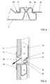
- Both rear side channels 2 and 3 are facing the front footwell Wall an opening 20 and 21 and in the facing the tunnel Wall 22 and 23 in the area of the respective opening 20, 21, a hole 24 and 25 respectively arranged, the border 26 and 27 in the interior of the respective rear side channel 2 or 3 is issued.
- the assembly is carried out in such a way that the two through the film hinge 10 together connected air inlet nozzle 6, 7 of the rear side channels 2, 3 with their walls 8, 9 merged and then in the (not shown) connecting piece of the ventilation and / or heater are introduced, with the locking and fixing bolts 13 and 14 in the tunnel-fixed mounting element (not shown) intervention. Then the fund-side end areas of the two fund-side channels 2 and 3 fixed to the vehicle body by the arranged on these Holding domes 15 and 16 pressed into the respective seat cross member 19 and there by the on the retaining domes 15, 16 arranged locking projections 17 and 18 are fixed. This means that the air duct with its two rear side ducts 2 and 3 is screwless, however firmly arranged on the vehicle body.
- the Opening 20 covers, while opening 21 through a corresponding recess in the cushioning surface D for ventilation and / or heating of the passenger footwell remains uncovered.
- this opening 21 there is a diaphragm over the damping coating D. 28 arranged, which can be fixed with an expansion clip 29 in the hole 25 by this issued border 27 of the hole engages behind.
- the inside of the rear side channel 3 located side wall 31 of the panel 28 is to the tunnel-side wall 23 angled towards to allow air outlet.
- the bezel 28 also instructs on its side facing the footwell, two reaching into the rear side channel 3, air guiding blades arranged at a distance behind one another - if necessary also adjustable 30 on the exiting air flow in a predetermined direction of exit to steer.
Description
Die Erfindung betrifft eine Luftkanalanordnung zur Fondbelüftung und/oder -heizung eines Kraftfahrzeugs, insbesondere eines Personenkraftwagens.The invention relates to an air duct arrangement for rear ventilation and / or heating a motor vehicle, especially a passenger car.
Heiz- und/oder Klimaanlagen für den Innenraum von Kraftfahrzeugen, die auch im Fondraum Luftauslaßöffnungen aufweisen, sind bekannt.Heating and / or air conditioning systems for the interior of motor vehicles, also in the rear room Air outlet openings are known.
So beschreibt die EP-0 458 705-A2 eine PKW-Belüftungs- und Heizanlage mit einem Belüftungs- und Heizgerät mit einer Verteilereinrichtung, die jeweils für die Front- und Seitenscheiben, den Fußbereich und den Innenraum getrennte Ausgänge bzw. Anschlüsse hat, wobei für den Fondbereich ein Anschluß für einen Luftkanal vorgesehen ist, der sich im Abstand vom Anschlußbereich in zwei Teilkanäle teilt, von denen jeder eine Fondseite gleichermaßen belüftet oder beheizt.For example, EP-0 458 705-A2 describes a car ventilation and heating system with one Ventilation and heating device with a distribution device, each for the front and Side windows, the foot area and the interior separate exits or connections has, with a connection for an air duct being provided for the rear area divides into two subchannels at a distance from the connection area, each one Rear side equally ventilated or heated.
Bekannt ist desweiteren, daß derartige Anlagen so ausgelegt werden können, daß beide Innenraumseitenhälften bezüglich Temperatur- und Luftdurchsatz getrennt voneinander regelbar sind. Derartige Weiterentwicklungen weisen ein Belüftungs- und/oder Heizgerät mit einem Luftgebläse, einem Steuergerät und einem Bediengerät auf, an das die erforderlichen Luftkanäle für die Frontscheiben-, die Seitenscheiben- und die Fußraumbelüftung und die Belüftung der verschiedenen Innenraumbereiche, jeweils mit entsprechenden Luftauslaßöffnungen, anschließbar sind, und über das das Mischungsverhältnis von Warm- und Kaltluft, aber auch der Luftdurchsatz für die aufgeführten Versorgungsbereiche unterschiedlich und individuell gewählt werden können.It is also known that such systems can be designed so that both Interior side halves separately in terms of temperature and air flow are adjustable. Such further developments have a ventilation and / or heating device with an air blower, a control unit and a control unit to which the required Air ducts for windscreen, side window and footwell ventilation and the ventilation of the various interior areas, each with appropriate Air outlet openings, can be connected, and the mixing ratio of warm and cold air, but also the air flow for the listed Supply areas can be selected differently and individually.
So beschreiben die EP-0 170 177-A1 und die EP-0 210 548-A2 jeweils eine Heiz- und Klimaanlage für den Innenraum von Personenkraftwagen, bei der auch die FondraumFahrerseite und die Fondraum-Beifahrerseite durch getrennt voneinander angeordnete Luftkanäle mit dem Heiz- und Klimagerät verbunden sind. Eine vergleichbare Lösung ist aus der EP-0 059 424-A2 bekannt. Die DE-30 43 548-C2 beschreibt getrennt voneinander regelbare Luftauslaßeinrichtungen, die im Bereich des Armaturenbrettes eines Kraftfahrzeugs angeordnet sind und von denen eine für den Fond vorgesehen ist, an der ein sich gabelförmig zu den beiden Fondseiten hin erstreckender Luftkanal über ein Anschlußstück angeschlosen ist, der beide Fondseiten gleichermaßen belüftet und beheizt.For example, EP-0 170 177-A1 and EP-0 210 548-A2 each describe a heating and Air conditioning for the interior of passenger cars, including the rear compartment driver's side and the rear passenger side by separately arranged Air ducts are connected to the heating and air conditioning unit. A comparable solution is known from EP-0 059 424-A2. DE-30 43 548-C2 describes separately from each other adjustable air outlet devices in the area of the dashboard Motor vehicle are arranged and one of which is provided for the rear, on the an air duct that extends in a fork-shaped manner to the two rear sides over a Connection is connected, which ventilates both sides of the fund and equally heated.
Die in den aufgeführten Lösungen gezeigten Luftkanäle und deren Anordnung zur individuellen Fondbelüftung und/oder -beheizung der beiden Fondseiten sind bezüglich ihres Erstellungs- und Montageaufwandes relativ aufwendig.The air ducts shown in the solutions listed and their arrangement for individual The rear ventilation and / or heating of the two sides of the fund are related to their Creation and assembly work relatively expensive.
Aufgabe der Erfindung ist es, eine Luftkanalanordnung zur Fondbelüftung- und/ oder - beheizung für ein Kraftfahrzeug, insbesondere einen Personenkraftwagen zu schaffen, mit der die beiden Fondseiten unterschiedlich belüftet- und/ oder beheizt werden können und bei der der Erstellungs- und Montageaufwand reduziert ist.The object of the invention is to provide an air duct arrangement for rear ventilation and / or to provide heating for a motor vehicle, in particular a passenger car, with which the two fund sides can be ventilated and / or heated differently and in which the construction and assembly work is reduced.
Diese Aufgabe wird bei einer Luftkanalanordnung nach dem Oberbegriff des Anspruchs
1 und wie aus US-A-4 681 153 bekannt, durch dessen kennzeichnende Merkmale gelöst. Dadurch, daß das Anschlußstück des
fondseitig in zwei Fondseitenkanäle geteilten und sich beidseits des Fahrzeugtunnels
erstreckenden Luftkanals zur Belüftung bzw. Beheizung der Fondseiten aus belüftungs-
und heizgeräteseitigen Lufteintrittsstutzen dieser beiden Fondseitenkanäle gebildet ist,
die dazu im Bereich des Einschubes in den Anschlußstutzen eines Belüftungs- und/oder
Heizgerätes parallel zueinander ausgerichtet sind und jeweils eine zur gegenseitigen
Anlage bringbare Wandung aufweisen, können die beiden Fondseiten unabhängig voneinander
und individuell wählbar belüftet und/ oder beheizt werden, da zwei voneinander
getrennte Lufteintrittsöffnungen gegeben sind. Außerdem sind der Fertigungs- und auch
der Montageaufwand für den Luftkanal reduziert, da dieser aus Kunststoff gefertigt und
mit seinen beiden über das Filmscharnier miteinander verbundenen Fondseitenkanälen in
einem Arbeitsgang und in einem Werkzeug vorzugsweise durch Blasformung hergestellt
werden und als Einheit transportiert und montiert werden kann.This object is achieved in an air duct arrangement according to the preamble of the
Die Maßnahme nach Anspruch 2 verhindert auf einfache Weise einen Luftdurchtritt
zwischen den Lufteintrittsstutzen der beiden Fondseitenkanäle. Die belüftungs- und/oder
heizgeräteseitige Fixierung der Luftkanalanordnung erfolgt vorteilhaft durch einen an
jedem der beiden Fondseitenkanäle angeordneten Arretierungs- und Fixierbolzen, der mit
einem am Fahrzeugtunnel angeordneten Halterungselement in Eingriff bringbar ist. Durch
die beiden Bolzen ist zugleich die vorbestimmte gegenseitige Lagezuordnung und Anordnung
der Lufteintrittsstutzen im Anschlußstutzen definiert gegeben.The measure according to
Im Zusammenhang mit der Maßnahme nach Anspruch 4, nach der die beiden Fondseitenkanäle
im fondseitigen Endbereich fahrzeugbodenseitig jeweils einen Haltedom mit
einem Rastvorsprung für den Eingriff in eine Sitzquerträgerausnehmung aufweisen und
der Haltedom ein Festlager für den jeweiligen Fondseitenkanal darstellt, können die
Fondseitenkanäle schraubenlos in vorbestimmter Weise am Fahrzeugaufbau befestigt
werden. Die Einschubstelle des Anschlußstückes in den Anschlußstutzen kann auf
einfache Weise durch einen flexiblen Faltenbalgschlauch oder eine Tülle luftdicht
umschlossen werden, so daß die vom Belüftungs- und/oder Heizgerät zur Luftkanalanordnung
gesteuerten Luftströme verlustlos in die Fondseitenkanäle einströmen.In connection with the measure according to
Die Fondseitenkanäle können im Bereich des jeweiligen vorderen Fußraumes auf der
dem Tunnel abgewandten Seite eine Öffnung aufweisen, die für die Belüftung- und/oder
Heizung des betreffenden Fußraumes benutzt werden kann. Beispielsweise ist es in
Abhängigkeit von der Fahrzeugkonzeption als Rechts- oder Linkslenker somit möglich,
die Öffnung des auf der Beifahrerseite verlaufenden Fondseitenkanals als Belüftungs-
und/ oder Heizöffnung zu nutzen und die des jeweils auf der Fahrerseite verlaufenden
Fondseitenkanals durch den Fahrzeugteppich bzw. den Dämpfungsbelag abzudecken.
Dadurch ist es möglich, auch nur den linken oder rechten vorderen Fahrzeugfußraum zu
belüften und/oder zu heizen, indem die Öffnung des jeweils anderen Fondseitenkanals
abgedeckt und damit verschlossen wird. Dadurch kann die Luftkanalanordnung ohne
zusätzlichen Aufwand gleichermaßen für als Rechts- oder als Linkslenker ausgelegte
Fahrzeuge verwendet werden. Soll also beispielsweise nur der Fußraum des Beifahrers
belüft- und/oder beheizbar ausgelegt werden, so kann nach Anspruch 7 die Öffnung des
jeweils auf der Fahrerseite angeordneten Fondseitenkanals durch den Fahrzeugteppich
bzw. den Dämpfungsbelag abgedeckt werden. Die Maßnahme nach Anspruch 8 dient
auf einfache Weise einer definierten Luftführung an der Belüftungsöffnung.The rear side channels can be in the area of the respective front footwell on the
side facing away from the tunnel have an opening for ventilation and / or
Heating the relevant footwell can be used. For example, it is in
Depending on the vehicle design as a right or left hand drive possible
the opening of the rear side channel running on the passenger side as ventilation
and / or to use the heating opening and that of the one running on the driver's side
Cover the rear side channel through the vehicle carpet or the damping covering.
This makes it possible to only close the left or right front vehicle footwell
ventilate and / or heat by opening the other rear side channel
is covered and thus closed. This allows the air duct arrangement without
additional effort equally for right-hand drive or left-hand drive
Vehicles are used. So, for example, only the footwell of the passenger
be designed to be ventilated and / or heatable, the opening of
each rear side channel through the vehicle carpet arranged on the driver's side
or the damping covering are covered. The measure according to
Nach Anspruch 9 kann die gemäß Anspruch 8 anordbare Blende auf einfache Weise mit
einem Spreizclip am jeweiligen Fondseitenkanal befestigt werden, indem an diesem in
der tunnelseitigen Wandung im Bereich der Öffnung ein Loch angeordnet ist, dessen
Umrandung in den Kanal hinein ausgestellt ist, in das der an der Blende arretierte Spreizclip
gedrückt wird und das Loch hintergreift, und dabei die Blende mit dem Fahrzeugteppich
am Fondseitenkanal fixiert. According to
Die Blende kann nach Anspruch 10 mit verstellbaren Lüftungslamellen versehen sein, so
daß der belüftungs- und/oder heizgeräteseitig für den Fondseitenkanal bezüglich Temperatur-
und Luftdurchsatz geregelte Luftstrom zusätzlich hinsichtlich seiner Auslaßrichtung
verändert werden kann.The panel can be provided with adjustable ventilation slats according to
Der in die beiden Fondseitenkanäle gabelförmig geteilte Luftkanal für den Fahrzeugfond
besteht vorteilhafterweise aus Polypropylen oder Polyethylen, was dessen Fertigung
vereinfacht, indem die Arretierungs- und Fixierbolzen nach Anspruch 3, aber auch die
Haltedome nach Anspruch 4 bei der Blasformung mit angebracht werden können.The forked air duct for the vehicle rear, divided into the two rear side ducts
advantageously consists of polypropylene or polyethylene, which is its manufacture
simplified by the locking and fixing bolts according to
Die Erfindung wird nachstehend anhand eines Ausführungsbeispiels erläutert. In der zugehörigen Zeichnung zeigen:
- Fig. 1:
- eine perspektivische Ansicht einer erfindungsgemäßen Luftkanalanordnung,
- Fig. 2:
- einen Ausschnitt der Stirnseitenansicht der Luftkanalanordnung,
- Fig. 3:
- eine Draufsicht auf das belüftungs- und/ oder heizgeräteseitige Anschlußstück des Luftkanals, teilweise geschnitten,
- Fig. 4:
- einen Schnitt durch einen Haltedom quer zur Längsrichtung des in Fahrzeugrichtung linken Fondseitenkanals und
- Fig. 5:
- einen Querschnitt durch den in Fahrzeugrichtung rechten Fondseitenkanal im Bereich der Belüftungsöffnung für den Beifahrerfußraum.
- Fig. 1:
- 2 shows a perspective view of an air duct arrangement according to the invention,
- Fig. 2:
- a detail of the end view of the air duct arrangement,
- Fig. 3:
- a top view of the ventilation duct and / or heater-side connector of the air duct, partially cut,
- Fig. 4:
- a section through a Haltedom transverse to the longitudinal direction of the left rear vehicle side channel and
- Fig. 5:
- a cross section through the right rear side channel in the vehicle direction in the area of the ventilation opening for the passenger footwell.
In Fig. 1 ist eine erfindungsgemäße Luftkanalanordnung aus Polypropylen für die Fondbelüftung
und/oder -heizung eines Personenkraftwagens dargestellt. Sie weist ein lufteintrittsseitiges
Anschlußstück 1 für einen Anschlußstutzen (nicht dargestellt) eines
Belüftungs- und/oder Heizgerätes auf, von dem fondseitig zwei sich gabelförmig zu
beiden Fondseiten hin ersteckende Fondseitenkanäle 2 und 3 ausgehen. Diese Fondseitenkanäle
2 und 3 sind beidseitig am Fahrzeugtunnel (nicht dargestellt), an diesem
anliegend, zu den Fondfußräumen geführt und weisen endseitig eine Luftauslaßöffnung
4 und 5 auf.In Fig. 1 is an air duct arrangement according to the invention made of polypropylene for the rear ventilation
and / or heating a passenger car shown. It has an air
Das Anschlußstück 1 ist aus den belüftungsgeräteseitigen Lufteintrittsstutzen 6 und 7
gebildet. Diese sind parallel zueinander ausgerichtet und weisen jeweils eine zur gegenseifigen
Anlage bringbare Wandung 8 und 9 auf, die auf ihrer dem Fahrzeugtunnel abgewandten
Seite durch ein Filmscharnier 10 miteinander verbunden sind, dessen Ausdehnung
hier nicht ganz an die Stirnkanten der Lufteintrittsstutzen heranreicht. Diese Freimachung
ermöglicht die Anformung teilumlaufender Rastwülste 6a und 7a, mit denen
ein aufzuschiebender und vorzugsweise am Anschlußstutzen gehaltener Faltenbalg
arretiert werden kann. Außderdem wird durch die verbesserte Anlage des Faltenbalgs an
den Fondseitenkanälen 2, 3 eine bessere Dichtwirkung erzielt. In den Wandungen 8 und
9 ist jeweils in geringem Abstand von der Lufteintrittsöffnung eine senkrecht zur Längsachse
der Lufteintrittsstutzen 6 und 7 und zur rechten Fahrzeugseite hin ausgebildete
vorzugsweise sickenartig ausgeführte Auswölbung 11 bzw. 12 zum gegenseitigen
Eingriff angeordnet (Fig. 2 und 3). Durch diese fixierende Maßnahme werden die Fondseitenkanäle
2, 3 gegen Axialverschiebungen gesichert. Außerdem wird so eine
Labyrinthdichtung erzeugt, die den Luftdurchtritt zwischen den Wandungen 8, 9 nahezu
vollständig unterbindet. An beiden Fondseitenkanälen 2 und 3 ist unterhalb ihres Lufteintrittstutzens
6 und 7 in Richtung ihrer Längsachse jeweils ein Arretierungs- und Fixierbolzen
13 und 14 für den Eingriff in ein tunnelfestes Halterungselement (nicht dargestellt)
ausgebildet. Beide Fondseitenkanäle 2 und 3 weisen im fondseitigen Endbereich
fahrzeugbodenseitig jeweils einen angespritzten Haltedom 15, 16 mit einem Rastvorsprung
17, 18 für den Eingriff in jeweils einen am Fahrzeugaufbau fest angeordneten
Sitzquerträger 19 auf, in dem eine entsprechende Ausnehmung vorhanden ist (Fig. 4). In
beiden Fondseitenkanälen 2 und 3 sind in der dem jeweils vorderen Fußraum zugewandten
Wandung eine Öffnung 20 bzw. 21 und in der dem Tunnel zugewandten
Wandung 22 und 23 im Bereich der jeweiligen Öffnung 20, 21 ein Loch 24 bzw. 25
angeordnet, dessen Umrandung 26 bzw. 27 in das Innere des jeweiligen Fondseitenkanals
2 bzw. 3 ausgestellt ist.The
Die Montage erfolgt in der Weise, daß die beiden durch das Filmscharnier 10 miteinander
verbundenen Lufteintrittstutzen 6, 7 der Fondseitenkanäle 2, 3 mit ihren Wandungen
8, 9 zusammengeführt und anschließend in den (nicht dargestellten) Anschlußstutzen
des Belüftungs- und/oder Heizgerätes eingeführt werden, wobei auch die Arretierungs-
und Fixierbolzen 13 und 14 in das (nicht dargestellte) tunnelfeste Halterungselement
eingreifen. Anschließend werden die fondseitigen Endbereiche der beiden Fondseitenkanäle
2 und 3 am Fahrzeugaufbau fixiert, indem die an diesen angeordneten
Haltedome 15 und 16 in den jeweiligen Sitzquerträger 19 gedrückt und dort durch die
an den Haltedomen 15, 16 angeordneten Rastvorsprünge 17 und 18 fixiert werden.
Damit ist der Luftkanal mit seinen beiden Fondseitenkanälen 2 und 3 schraubenlos,
jedoch fest am Fahrzeugaufbau angeordnet. The assembly is carried out in such a way that the two through the film hinge 10 together
connected
Anschließend wird ein flexibler Faltenbalgschlauch, der zuvor in Parkstellung auf dem
Anschlußstutzen oder dem Anschlußstück angeordnet wurde, über den mit den Rastwülsten
6a und 7a versehenen Einschubbereich geschoben, um diesen luftdicht abzuschließen.
Der textile Dämpfungsbelag ist über der Luftkanalanordnung vorzugsweise
bereits vor der Montage des Anschlußstutzens verlegt worden.Then a flexible bellows hose, which was previously in the park position on the
Connection piece or the connector was arranged over the with the locking
In der Ausführungsform für einen Personenkraftwagen mit Linkslenkung wird dabei die
Öffnung 20 überdeckt, während die Öffnung 21 durch eine entsprechende Ausnehmung
im Dämpfungsbelag D zur Fußraumbelüftung und/oder -heizung des Beifahrerfußraumes
unabgedeckt bleibt. In dieser Öffnung 21 wird über dem Dämpfungsbelag D eine Blende
28 angeordnet, die mit einem Spreizclip 29 im Loch 25 fixierbar ist, indem dieser die
ausgestellte Umrandung 27 des Loches hintergreift. Die im Innern des Fondseitenkanals
3 befindliche Seitenwandung 31 der Blende 28 ist zu dessen tunnelseitiger Wandung 23
hin abgewinkelt, um einen Luftauslaß zu ermöglichen. Überdies weist die Blende 28 an
ihrer dem Fußraum zugewandten Seite zwei in den Fondseitenkanal 3 hineinreichende,
im Abstand hintereinander angeordnete - ggfs. auch verstellbar ausgeführte - Luftführungslamellen
30 auf, die den austretenden Luftstrom in eine vorbestimmte Austrittrichtung
lenken.In the embodiment for a passenger car with left-hand drive, the
Claims (11)
- Air duct arrangement for rear ventilation and/or heating having an air-inlet connecting piece (1) for a connecting branch of a ventilating and/or heating device, and two rear-side ducts (2 and 3), which emerge in the rear from the connecting piece (1), extend in a forked manner on both sides of the vehicle tunnel to both sides of the rear and each have an air-outlet opening (5) on their end side, characterized in that the connecting piece (1) is formed from air-inlet connecting branches (6 and 7) of the two rear-side ducts (2 and 3), which connecting branches come from the ventilating and/or heating device, are aligned essentially parallel to each other and each have at least one wall (8, 9) which can be brought into mutual contact, and in that on the side facing away from the vehicle tunnel the air-inlet connecting branches (6, 7) are connected to each other along the walls (8, 9) by at least one film hinge (10).
- Air duct arrangement according to Claim 1, characterized in that the walls (8 and 9) have, for the mutual engagement, a respective bead-shaped convexity (11, 12) arranged essentially perpendicularly with respect to the longitudinal axis of the air-inlet connecting branch (6, 7), at a short distance from the respective air-inlet opening.
- Air duct arrangement according to Claim 1 or 2, characterized in that the rear-side ducts (2, 3) have, below the air-inlet connecting branches (6, 7), a locking and fixing bolt (13, 14) for engagement in a securing element fixed on the tunnel.
- Air duct arrangement according to Claims 1, 2 or 3, characterized in that the rear-side ducts (2, 3) have, on the vehicle floor in the rear end region, a respective retaining dome (15, 16) having a latching projection (17, 18) for engagement in a seat-rail recess.
- Air duct arrangement according to Claim 1 or one of the following claims, characterized in that the region in which the connecting piece (1) is inserted into the connecting branch is surrounded by a flexible bellows-type hose.
- Air duct arrangement according to Claim 1 or one of the following claims, characterized in that the rear-side ducts (2, 3) have, in the region of the front foot well, an opening (20, 21) in their wall facing away from the tunnel.
- Air duct arrangement according to Claim 6, characterized in that the opening (20, 21) in the rear-side duct (2 or 3) extending in each case on the front-passenger's side can be used as a ventilation opening, and the rear-side duct (3 or 2) extending on the driver's side can be covered by the damping covering (D).
- Air duct arrangement according to Claim 6 or 7, characterized in that the ventilation opening (20, 21) opens into the foot well through a cutout in the damping covering (D) and is provided with a cover (28) which can be inserted and fixed on the damping side and has air-guiding fins (30) reaching into the rear-side duct (2, 3).
- Air duct arrangement according to Claim 8, characterized in that the cover 28) can be fastened with an expanding clip (29) on a hole (24, 25) which is arranged opposite the opening (20, 21) in the tunnel-side wall (22, 23) of the respective rear-side duct (2, 3) and has its edge protruding into the rear-side duct (2, 3).
- Air duct arrangement according to Claim 8, characterized in that the air-guiding fins (30) can be adjusted.
- Air duct arrangement according to Claim 1 or one or more of the following claims, characterized in that the rear-side ducts (2, 3) are manufactured from propylene or polyethylene.
Applications Claiming Priority (2)
| Application Number | Priority Date | Filing Date | Title |
|---|---|---|---|
| DE19602956 | 1996-01-27 | ||
| DE19602956 | 1996-01-27 |
Publications (3)
| Publication Number | Publication Date |
|---|---|
| EP0786363A2 EP0786363A2 (en) | 1997-07-30 |
| EP0786363A3 EP0786363A3 (en) | 1999-06-16 |
| EP0786363B1 true EP0786363B1 (en) | 2002-05-29 |
Family
ID=7783874
Family Applications (1)
| Application Number | Title | Priority Date | Filing Date |
|---|---|---|---|
| EP97100163A Expired - Lifetime EP0786363B1 (en) | 1996-01-27 | 1997-01-08 | Air duct arrangement for the aeration or heating of the rear passenger compartiment of a vehicle |
Country Status (2)
| Country | Link |
|---|---|
| EP (1) | EP0786363B1 (en) |
| DE (1) | DE59707343D1 (en) |
Families Citing this family (8)
| Publication number | Priority date | Publication date | Assignee | Title |
|---|---|---|---|---|
| JP2003034115A (en) * | 2001-07-23 | 2003-02-04 | Mitsubishi Heavy Ind Ltd | Automotive air-conditioning duct |
| FR2836659B1 (en) * | 2002-03-01 | 2004-05-28 | Renault | MOTOR VEHICLE VENTILATION GRILLE PROVIDED FOR MOUNTING ON A MOTOR VEHICLE FLOOR |
| FR2871101A1 (en) * | 2004-06-02 | 2005-12-09 | Renault Sas | Covering device for passenger compartment of motor vehicle, has air distribution conduit comprising outlet section with outlet orifice situated above rear cellar such that orifice is situated above upper front edge of trough receiving feet |
| DE102005011832B4 (en) * | 2005-03-15 | 2011-01-20 | Audi Ag | Air guiding device for a vehicle |
| DE102009008274A1 (en) * | 2009-02-10 | 2010-08-12 | GM Global Technology Operations, Inc., Detroit | Drain hose system for a motor vehicle air conditioning |
| DE102012106402A1 (en) | 2012-07-17 | 2014-05-15 | Dr. Ing. H.C. F. Porsche Aktiengesellschaft | Motor vehicle e.g. passenger car has air guide channel that is arranged on underside of central console via clamp connection, and sleeve that is arranged for carrying out tolerance compensation in longitudinal direction of housing |
| JP7295049B2 (en) * | 2020-01-30 | 2023-06-20 | トヨタ自動車株式会社 | vehicle structure |
| EP3964372A1 (en) * | 2020-09-03 | 2022-03-09 | TI Automotive Technology Center GmbH | Tube assembly for transporting temperature control media |
Family Cites Families (10)
| Publication number | Priority date | Publication date | Assignee | Title |
|---|---|---|---|---|
| US2882809A (en) * | 1957-09-17 | 1959-04-21 | Glenn J Nelson | Air duct for motor vehicles |
| US4191242A (en) * | 1977-03-28 | 1980-03-04 | Mitsubishi Jidosha Kogyo Kabushiki Kaisha | Air conditioner operating apparatus |
| JPS5674551A (en) | 1979-11-20 | 1981-06-20 | Nissan Motor Co Ltd | Fluid blowing-off structure |
| JPS57144116A (en) | 1981-02-27 | 1982-09-06 | Nissan Motor Co Ltd | Room heater for vehicle |
| JPS59186117U (en) * | 1983-05-31 | 1984-12-11 | 日産車体株式会社 | Automotive air conditioner |
| DE3427292A1 (en) | 1984-07-24 | 1986-01-30 | Bayerische Motoren Werke AG, 8000 München | HEATING AND AIR CONDITIONING IN MOTOR VEHICLES |
| DE3660992D1 (en) | 1985-06-26 | 1988-12-01 | Bayerische Motoren Werke Ag | Heating and/or air conditioning device for a motor vehicle interior compartment, particularly for a passenger vehicle |
| DE3909813A1 (en) * | 1989-03-24 | 1990-09-27 | Vogelsang Ernst Gmbh Co Kg | CABLE GUIDE TUBE BUNDLE FROM A MULTIPLE PLASTIC PIPES |
| DE3940361A1 (en) * | 1989-12-06 | 1991-06-13 | Bayerische Motoren Werke Ag | Conditioning system for motor vehicle - has separate control of temp. of air supplied to rear passengers |
| JP2566044B2 (en) | 1990-05-25 | 1996-12-25 | 日産自動車株式会社 | Heater unit structure of vehicle air conditioner |
-
1997
- 1997-01-08 EP EP97100163A patent/EP0786363B1/en not_active Expired - Lifetime
- 1997-01-08 DE DE59707343T patent/DE59707343D1/en not_active Expired - Lifetime
Also Published As
| Publication number | Publication date |
|---|---|
| DE59707343D1 (en) | 2002-07-04 |
| EP0786363A3 (en) | 1999-06-16 |
| EP0786363A2 (en) | 1997-07-30 |
Similar Documents
| Publication | Publication Date | Title |
|---|---|---|
| DE2813909C2 (en) | Instrument panel for automobiles | |
| DE3529940C3 (en) | Heating and air conditioning device for motor vehicles | |
| DE19731908B4 (en) | Heating and air conditioning for a motor vehicle | |
| DE60225979T2 (en) | Device for generating a temperature-controlled air flow for a motor vehicle passenger compartment and heating and / or air conditioning with such a safety device | |
| DE10037384B4 (en) | Heating and air conditioning for a motor vehicle | |
| EP1560723A1 (en) | Device and method for air distribution in a vehicle | |
| EP0200899B1 (en) | Apparatus for ventilating and air conditioning driver's areas, driver's cabs or the like | |
| EP0663309B1 (en) | Heating or airconditioning device, in particular for installation in a motorvehicle | |
| EP0786363B1 (en) | Air duct arrangement for the aeration or heating of the rear passenger compartiment of a vehicle | |
| DE10242805A1 (en) | Internal ventilation system for road vehicle has plate with several holes set in roof lining and has gap round edge of central plate to allow radial escape of ventilating air | |
| DE19804287C1 (en) | Air conditioner for motor vehicle interior | |
| DE102009044760B4 (en) | Air conditioning for a motor vehicle | |
| DE3608524A1 (en) | Heating and ventilation device | |
| EP1228907B1 (en) | Air conditioning device for a motor vehicle | |
| DE4243165A1 (en) | Automotive air-conditioning unit | |
| DE102007029635A1 (en) | Device for cooling electronic components | |
| DE10062151B4 (en) | Instrument panel, in particular for a motor vehicle, with a base body and a cover | |
| DE102007049340A1 (en) | Motor vehicle air conditioning arrangement | |
| DE19540020A1 (en) | Modular unit for motor vehicle body | |
| DE10042683A1 (en) | Air conditioning unit for motor vehicles has two housing sections ate 90o to each other, and connected via flow channel connector | |
| DE19742566C1 (en) | Air separator for motor vehicle interior | |
| DE102018121528A1 (en) | Heating / air conditioning unit for a motor vehicle | |
| DE10045438A1 (en) | Air conditioning for a motor vehicle | |
| DE102008013450A1 (en) | Passenger compartment air conditioning system for use in e.g. minivan, has discharge nozzle for fluid medium warmed up in vehicle, where fluid medium or air or both fluid medium and air are used for air conditioning of vehicle | |
| DE19816330C1 (en) | Heating or air conditioning assembly for motor vehicle |
Legal Events
| Date | Code | Title | Description |
|---|---|---|---|
| PUAI | Public reference made under article 153(3) epc to a published international application that has entered the european phase |
Free format text: ORIGINAL CODE: 0009012 |
|
| AK | Designated contracting states |
Kind code of ref document: A2 Designated state(s): DE FR GB IT |
|
| PUAL | Search report despatched |
Free format text: ORIGINAL CODE: 0009013 |
|
| AK | Designated contracting states |
Kind code of ref document: A3 Designated state(s): DE FR GB IT |
|
| 17P | Request for examination filed |
Effective date: 19991216 |
|
| RTI1 | Title (correction) |
Free format text: AIR DUCT ARRANGEMENT FOR THE AERATION OR HEATING OF THE REAR PASSENGER COMPARTIMENT OF A VEHICLE |
|
| GRAG | Despatch of communication of intention to grant |
Free format text: ORIGINAL CODE: EPIDOS AGRA |
|
| 17Q | First examination report despatched |
Effective date: 20010605 |
|
| GRAG | Despatch of communication of intention to grant |
Free format text: ORIGINAL CODE: EPIDOS AGRA |
|
| GRAH | Despatch of communication of intention to grant a patent |
Free format text: ORIGINAL CODE: EPIDOS IGRA |
|
| GRAH | Despatch of communication of intention to grant a patent |
Free format text: ORIGINAL CODE: EPIDOS IGRA |
|
| GRAA | (expected) grant |
Free format text: ORIGINAL CODE: 0009210 |
|
| AK | Designated contracting states |
Kind code of ref document: B1 Designated state(s): DE FR GB IT |
|
| REG | Reference to a national code |
Ref country code: GB Ref legal event code: FG4D Free format text: NOT ENGLISH |
|
| REF | Corresponds to: |
Ref document number: 59707343 Country of ref document: DE Date of ref document: 20020704 |
|
| GBT | Gb: translation of ep patent filed (gb section 77(6)(a)/1977) |
Effective date: 20020729 |
|
| ET | Fr: translation filed | ||
| PLBE | No opposition filed within time limit |
Free format text: ORIGINAL CODE: 0009261 |
|
| STAA | Information on the status of an ep patent application or granted ep patent |
Free format text: STATUS: NO OPPOSITION FILED WITHIN TIME LIMIT |
|
| 26N | No opposition filed |
Effective date: 20030303 |
|
| PGFP | Annual fee paid to national office [announced via postgrant information from national office to epo] |
Ref country code: DE Payment date: 20110131 Year of fee payment: 15 |
|
| PGFP | Annual fee paid to national office [announced via postgrant information from national office to epo] |
Ref country code: GB Payment date: 20120131 Year of fee payment: 16 Ref country code: IT Payment date: 20120125 Year of fee payment: 16 |
|
| PG25 | Lapsed in a contracting state [announced via postgrant information from national office to epo] |
Ref country code: DE Free format text: LAPSE BECAUSE OF NON-PAYMENT OF DUE FEES Effective date: 20120801 |
|
| REG | Reference to a national code |
Ref country code: DE Ref legal event code: R119 Ref document number: 59707343 Country of ref document: DE Effective date: 20120801 |
|
| PGFP | Annual fee paid to national office [announced via postgrant information from national office to epo] |
Ref country code: FR Payment date: 20130219 Year of fee payment: 17 |
|
| GBPC | Gb: european patent ceased through non-payment of renewal fee |
Effective date: 20130108 |
|
| PG25 | Lapsed in a contracting state [announced via postgrant information from national office to epo] |
Ref country code: GB Free format text: LAPSE BECAUSE OF NON-PAYMENT OF DUE FEES Effective date: 20130108 |
|
| PG25 | Lapsed in a contracting state [announced via postgrant information from national office to epo] |
Ref country code: IT Free format text: LAPSE BECAUSE OF NON-PAYMENT OF DUE FEES Effective date: 20130108 |
|
| REG | Reference to a national code |
Ref country code: FR Ref legal event code: ST Effective date: 20140930 |
|
| PG25 | Lapsed in a contracting state [announced via postgrant information from national office to epo] |
Ref country code: FR Free format text: LAPSE BECAUSE OF NON-PAYMENT OF DUE FEES Effective date: 20140131 |