EP0778562B1 - Magnetic recording and reproducing apparatus - Google Patents
Magnetic recording and reproducing apparatus Download PDFInfo
- Publication number
- EP0778562B1 EP0778562B1 EP96119647A EP96119647A EP0778562B1 EP 0778562 B1 EP0778562 B1 EP 0778562B1 EP 96119647 A EP96119647 A EP 96119647A EP 96119647 A EP96119647 A EP 96119647A EP 0778562 B1 EP0778562 B1 EP 0778562B1
- Authority
- EP
- European Patent Office
- Prior art keywords
- recording
- magnetic
- head
- reproducing
- tape
- Prior art date
- Legal status (The legal status is an assumption and is not a legal conclusion. Google has not performed a legal analysis and makes no representation as to the accuracy of the status listed.)
- Expired - Lifetime
Links
- 230000004907 flux Effects 0.000 claims description 56
- 239000010409 thin film Substances 0.000 claims description 40
- 239000010408 film Substances 0.000 claims description 33
- 239000002184 metal Substances 0.000 claims description 24
- 230000004044 response Effects 0.000 claims description 13
- 230000015572 biosynthetic process Effects 0.000 claims description 12
- 239000000696 magnetic material Substances 0.000 claims description 8
- 238000010276 construction Methods 0.000 description 31
- 230000007704 transition Effects 0.000 description 21
- 230000000694 effects Effects 0.000 description 18
- 238000010586 diagram Methods 0.000 description 12
- 230000009467 reduction Effects 0.000 description 10
- 230000006872 improvement Effects 0.000 description 9
- 230000005415 magnetization Effects 0.000 description 8
- 238000000034 method Methods 0.000 description 8
- 230000007423 decrease Effects 0.000 description 7
- 239000002923 metal particle Substances 0.000 description 7
- 238000006243 chemical reaction Methods 0.000 description 6
- 230000002238 attenuated effect Effects 0.000 description 4
- 238000013461 design Methods 0.000 description 4
- 230000006866 deterioration Effects 0.000 description 4
- 238000001704 evaporation Methods 0.000 description 3
- 239000005001 laminate film Substances 0.000 description 3
- 230000007246 mechanism Effects 0.000 description 3
- 239000000203 mixture Substances 0.000 description 3
- 229910000859 α-Fe Inorganic materials 0.000 description 3
- 229910020647 Co-O Inorganic materials 0.000 description 2
- 229910020704 Co—O Inorganic materials 0.000 description 2
- 230000008859 change Effects 0.000 description 2
- 238000000151 deposition Methods 0.000 description 2
- 230000008021 deposition Effects 0.000 description 2
- 238000001514 detection method Methods 0.000 description 2
- 230000008020 evaporation Effects 0.000 description 2
- 238000002474 experimental method Methods 0.000 description 2
- 239000000284 extract Substances 0.000 description 2
- 238000011160 research Methods 0.000 description 2
- 230000002411 adverse Effects 0.000 description 1
- 238000007796 conventional method Methods 0.000 description 1
- 230000001419 dependent effect Effects 0.000 description 1
- 238000011161 development Methods 0.000 description 1
- 238000009792 diffusion process Methods 0.000 description 1
- 239000011521 glass Substances 0.000 description 1
- 238000007733 ion plating Methods 0.000 description 1
- 239000006247 magnetic powder Substances 0.000 description 1
- 238000005259 measurement Methods 0.000 description 1
- 238000005457 optimization Methods 0.000 description 1
- 238000012545 processing Methods 0.000 description 1
- 229920006395 saturated elastomer Polymers 0.000 description 1
- 238000001228 spectrum Methods 0.000 description 1
- 238000004544 sputter deposition Methods 0.000 description 1
- 239000000758 substrate Substances 0.000 description 1
Images


Classifications
-
- G—PHYSICS
- G11—INFORMATION STORAGE
- G11B—INFORMATION STORAGE BASED ON RELATIVE MOVEMENT BETWEEN RECORD CARRIER AND TRANSDUCER
- G11B5/00—Recording by magnetisation or demagnetisation of a record carrier; Reproducing by magnetic means; Record carriers therefor
- G11B5/127—Structure or manufacture of heads, e.g. inductive
- G11B5/147—Structure or manufacture of heads, e.g. inductive with cores being composed of metal sheets, i.e. laminated cores with cores composed of isolated magnetic layers, e.g. sheets
-
- G—PHYSICS
- G11—INFORMATION STORAGE
- G11B—INFORMATION STORAGE BASED ON RELATIVE MOVEMENT BETWEEN RECORD CARRIER AND TRANSDUCER
- G11B5/00—Recording by magnetisation or demagnetisation of a record carrier; Reproducing by magnetic means; Record carriers therefor
-
- G—PHYSICS
- G11—INFORMATION STORAGE
- G11B—INFORMATION STORAGE BASED ON RELATIVE MOVEMENT BETWEEN RECORD CARRIER AND TRANSDUCER
- G11B5/00—Recording by magnetisation or demagnetisation of a record carrier; Reproducing by magnetic means; Record carriers therefor
- G11B5/008—Recording on, or reproducing or erasing from, magnetic tapes, sheets, e.g. cards, or wires
- G11B5/00813—Recording on, or reproducing or erasing from, magnetic tapes, sheets, e.g. cards, or wires magnetic tapes
-
- G—PHYSICS
- G11—INFORMATION STORAGE
- G11B—INFORMATION STORAGE BASED ON RELATIVE MOVEMENT BETWEEN RECORD CARRIER AND TRANSDUCER
- G11B5/00—Recording by magnetisation or demagnetisation of a record carrier; Reproducing by magnetic means; Record carriers therefor
- G11B5/02—Recording, reproducing, or erasing methods; Read, write or erase circuits therefor
- G11B5/09—Digital recording
-
- G—PHYSICS
- G11—INFORMATION STORAGE
- G11B—INFORMATION STORAGE BASED ON RELATIVE MOVEMENT BETWEEN RECORD CARRIER AND TRANSDUCER
- G11B5/00—Recording by magnetisation or demagnetisation of a record carrier; Reproducing by magnetic means; Record carriers therefor
- G11B5/127—Structure or manufacture of heads, e.g. inductive
- G11B5/187—Structure or manufacture of the surface of the head in physical contact with, or immediately adjacent to the recording medium; Pole pieces; Gap features
- G11B5/21—Structure or manufacture of the surface of the head in physical contact with, or immediately adjacent to the recording medium; Pole pieces; Gap features the pole pieces being of ferrous sheet metal or other magnetic layers
-
- G—PHYSICS
- G11—INFORMATION STORAGE
- G11B—INFORMATION STORAGE BASED ON RELATIVE MOVEMENT BETWEEN RECORD CARRIER AND TRANSDUCER
- G11B5/00—Recording by magnetisation or demagnetisation of a record carrier; Reproducing by magnetic means; Record carriers therefor
- G11B5/127—Structure or manufacture of heads, e.g. inductive
- G11B5/187—Structure or manufacture of the surface of the head in physical contact with, or immediately adjacent to the recording medium; Pole pieces; Gap features
- G11B5/23—Gap features
-
- G—PHYSICS
- G11—INFORMATION STORAGE
- G11B—INFORMATION STORAGE BASED ON RELATIVE MOVEMENT BETWEEN RECORD CARRIER AND TRANSDUCER
- G11B5/00—Recording by magnetisation or demagnetisation of a record carrier; Reproducing by magnetic means; Record carriers therefor
- G11B5/127—Structure or manufacture of heads, e.g. inductive
- G11B5/187—Structure or manufacture of the surface of the head in physical contact with, or immediately adjacent to the recording medium; Pole pieces; Gap features
- G11B5/245—Structure or manufacture of the surface of the head in physical contact with, or immediately adjacent to the recording medium; Pole pieces; Gap features comprising means for controlling the reluctance of the magnetic circuit in a head with single gap, for co-operation with one track
-
- G—PHYSICS
- G11—INFORMATION STORAGE
- G11B—INFORMATION STORAGE BASED ON RELATIVE MOVEMENT BETWEEN RECORD CARRIER AND TRANSDUCER
- G11B5/00—Recording by magnetisation or demagnetisation of a record carrier; Reproducing by magnetic means; Record carriers therefor
- G11B5/74—Record carriers characterised by the form, e.g. sheet shaped to wrap around a drum
- G11B5/78—Tape carriers
Definitions
- the invention relates to a magnetic recording and reproducing apparatus having the features of the preamble of claim 1.
- Such an apparatus is known from JP 5 182 172.
- a magnetic recording and reproducing apparatus in order to realize a miniaturization and a large capacity, there is a tendency at present to realize a high-density recording.
- a magnetic tape memory apparatus in order to improve recording and reproducing characteristics in a high recording density region, various researches related to a magnetic tape and a magnetic head have been performed.
- a magnetic recording medium in order to improve recording and reproducing resolutions in the high recording density region, it is necessary to increase a residual magnetization, realize a high coercive force to match the magnitude of the residual magnetization, and thin a magnetic layer.
- a medium that is superior to a conventional coated magnetic recording medium a thin film magnetic recording medium made by a vacuum evaporating method, a sputtering method, an ion plating method, or the like attracts attention.
- the magnetic tape is characterized by having an oblique magnetic anisotropy such that an easy axis is inclined from a film normal direction of a magnetic layer. That is, the easy axis is not located in a film plane or in the film normal direction but the axis is located in the direction which is inclined from the film normal direction in a normal plane including the longitudinal direction of the tape.
- the easy axis is inclined from the film normal direction by about 70° in the normal plane including the longitudinal direction of the tape.
- a magnetization recorded by a ring type magnetic head is remained in the inclined easy axis direction, thereby forming a magnetization mode different from a conventional longitudinal recording. Due to the formation of such an inclined magnetization mode, the high recording density characteristics are remarkably improved as compared with that of the longitudinal record medium.
- the coated tape which forms a longitudinal magnetization mode
- the coated tape such as an MP (metal particle) tape or the like has been a main stream as well.
- a magnetic head parameter (or dimension) in a recording step and a magnetic head parameter (or dimension) in a reproducing step can be independently designed. That is, from a point to improve the recording and reproducing characteristics, the head parameters or dimensions having what is called a trade-off relation in a self recording and reproducing system are individually optimized in the recording and reproducing steps, so that excellent recording and reproducing performances can be obtained.
- a gap length of the reproducing head is designed so as to be properly small in correspondence to a recording signal band and a gap length of the recording head is designed so as to be larger than that of the reproducing head.
- the gap length of the reproducing head It is necessary to design the gap length of the reproducing head as small as possible in order to reduce a gap loss in a high linear recording density region.
- the gap length of the recording head is miniaturized so as to be almost the same as that of the reproducing head, an enough recording magnetic field cannot be obtained and a tape magnetic layer cannot be saturation recorded, so that a problem such that a reproduction output is deteriorated, enough overwrite characteristics cannot be obtained, or the like occurs.
- the magnetic layer of the conventional coated tape is thicker than that of the thin film tape, so that it is difficult to completely record up to a deep layer of the magnetic layer.
- the gap length of the reproducing head is set to about 0.20 ⁇ m and the gap length of the recording head is set to 0.25 ⁇ m or more.
- the magnetic head parameters for recording and reproduction are optimized for the coated tape.
- the thin film magnetic tape When the thin film magnetic tape is used for the separately recording and reproducing system, an excellent performance of the thin film type tape is not necessarily exhibited. For instance, in a system optimized for the MP tape, irrespective of using the thin film tape, a case where only an S/N ratio that is equivalent to that of the MP tape is obtained also occurs.
- JP 2310818 discloses a magnetic recording and reproducing apparatus with a head device having a gap for read/write and a gap for servo, wherein the gap for read/write is smaller than the gap for servo. This system is used to respectively read data and servo information.
- the invention is, therefore, made in consideration of the above subjects, and it is the object of the present invention to provide a magnetic recording and reproducing apparatus, according to a separate recording and reproducing method, using a thin film magnetic tape as a medium, which can achieve maximum performance of the thin film magnetic tape.
- the inventor et al. of the present invention examined with respect to constructions of the recording and reproducing heads suitable for using a thin film tape having an oblique magnetic anisotropy as described above. Thus, they discovered that it is desirable that the gap length of the recording head is set to a value of about a thickness of the magnetic layer of the tape or less and that the gap length of the reproducing head is set to a value that is slightly larger than that of the recording head. Such a fact is quite different from a case of a magnetic recording and reproducing apparatus using a coated tape.
- an easy axis which is obliquely inclined and a recording magnetic field direction on a leading edge side of the recording head are inclined in the same direction with respect to the film normal direction of the tape, thereby recording a signal onto the thin film tape.
- the recording magnetic field on the leading edge side of the recording head has a large magnetic field component in the easy direction.
- the recording magnetic field on a trailing edge side has a large magnetic field component in a hard direction of the tape and has a very small magnetic field component in the easy direction.
- the magnetic field on the leading edge side mainly contributes to a magnetic reversal in the magnetic layer of the tape.
- the component in the easy direction of the head magnetic field is promptly attenuated. It is, therefore, considered that a magnetic transition steeper than that of the conventional longitudinal recording is obtained.
- Modulation noises of the thin film tape are caused by a zigzag domain of a magnetic transition region. Since the noises have a peak in a band region near a recording wavelength of 1 ⁇ m in which the highest reproduction output is obtained and a utility value is high in the thin film magnetic tape, the noises become a serious factor which influences an S/N ratio of the magnetic recording and reproducing system.
- the recording at a high resolution having a steep magnetic transition region is performed, the zigzag domain of the magnetic transition region decreases, and the noises caused thereby can also be reduced.
- a thickness of the magnetic layer of the thin film tape is thin, namely, equal to about 180 nm or less and a coercive force is equal to about 130 kA/m or less.
- the gap length of the recording head when recording onto the thin film tape is smaller than the thickness of the coated tape, preferably equal to about 0.17 ⁇ m or less.
- a thickness of magnetic layer of the thin film magnetic tape is equal to about 150 nm or less, preferably, about 100 nm or less.
- the recording can be sufficiently performed up to a deep layer in the magnetic layer and, as the gap length is set to be narrower, the improvement in recording characteristics is recognized.
- the thickness of the magnetic layer is larger than 180 nm, there is a tendency that an effect due to the narrow gap recording of the invention gradually decreases.
- the effect due to the narrow gap length in the above construction naturally depends not only on a thickness of the magnetic layer of the thin film tape but also on magnetic characteristics. Namely, it is desirable that the magnetic layer has a high orientation and a high magnetic anisotropy constant. According to the examination of the inventor et al. of the invention, in order to sufficiently obtain the effect in the recording due to the narrow gap length, it is preferable that a uniaxial anisotropy constant of the tape magnetic layer is equal to or larger than (2 x 10⁵) J/m3.
- the recording gap length is optimized within a range in which the effect due to the narrow gap recording is obtained.
- a reproducing step will now be described hereinbelow.
- the gap length of the reproducing head As mentioned above, from the viewpoint to reduce a gap loss in a high linear recording density region, it is necessary to design the gap length of the reproducing head as small as possible. That is, in the above-mentioned future magnetic tape memory apparatus having a linear recording density of a reversal flux of 150 kfrpi or more (minimum reversal interval of 0.17 ⁇ m or less), from the viewpoint of the reduction in gap loss, when the gap length of the reproducing head is smaller than that of the recording head and, desirably, it is equal to about 0.10 ⁇ m or less, a high reproduction output can be obtained in a high linear recording density region.
- the gap length of the reproducing head therefore, in order to obtain a maximum S/N ratio in consideration of the band region necessary for the magnetic recording and reproducing system, optimum dimensions (or parameters) have to be selected by comparing the increase in output due to the reduction in gap loss with the magnetic flux conversion efficiency. Consequently, according to the examination of the inventor et al. of the invention, it is desirable to set the gap length of the reproducing head to be slightly larger than that of the recording head.
- the effect by the construction is more valid when partial response Class 4 [PR (1, 0, -1)] or Class 1 [PR (1, 1)] is used as a detecting system of a reproduction signal.
- an interference between reproduction codes becomes a cause of a data detection error.
- an equalization to deform a spread waveform is performed. Hitherto, consequently, a detecting system for performing an integral equalization to compensate differential characteristics which occur due to the magnetic recording and reproduction and to suit equalization characteristics to Nyquist characteristics in which no inter-code interference occurs has been used.
- an S/N ratio at a detection point after completion of the equalization can be improved without emphasizing noises of a high band.
- a linear recording density that is higher than that of the conventional system can be realized.
- impulse (0, 0, 0, 1, 0, 0, 0) is handled as (0, 0, 0, 1, 1, 0, 0, 0) in partial response Class 1 and is handled as (0, 0, 0, 1, 0, -1, 0, 0, 0) in partial response Class 4.
- the former is expressed as PR (1, 1) and the latter is expressed as PR (1, 0, -1).
- PR (1, 0, -1) the impulse response
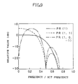
- Fig. 9 shows equalization characteristics of PR (1, 1) and PR (1, 0, -1) together with the ordinary Nyquist equalization characteristics of PR (1) (Etoh, "Signal processing technique for digital recording", the magazine of The Institute of Television Engineers of Japan, Vol. 45, No. 12, pp. 1511 to 1514, 1991).
- a signal output at 0.5 in an axis of abscissa namely, at the frequency 1/2T corresponding to the bit period T is processed as 0.
- a reproduction output and noises at 0.25 in the axis of abscissa namely, in a band region near a frequency 1/4T or in a band region of a further lower frequency are regarded as important, so that it is known that a dominant influence is exerted on an S/N ratio.
- partial response Class 1 and Class 4 even when the reproduction output of the magnetic recording and reproducing system in a high linear recording density region near the frequency 1/2T corresponding to the bit period T is slightly inferior, a necessary S/N ratio can be satisfied by a signal component of a low band in which the shorter wavelength loss is little. Therefore, the partial response Class 1 and Class 4 are suitable for realization of a high linear recording density of the apparatus.
- the high resolution recording having a steep magnetic transition and low noise components can be performed by the recording head with the narrow gap.
- the reproducing step although a reproduction output in a high linear recording density region is slightly low due to the gap loss, a high reproduction output can be obtained by realizing a high magnetic flux conversion efficiency in a relative low linear recording density region. According to the construction of the invention, therefore, characteristics of the magnetic recording and reproducing system which is very suitable to the reproducing system using above partial response Class 4 or Class 1 can be realized.
- the gap length of recording head is set to an enough small value and the gap length of reproducing head is set to a value slightly larger than that of the recording head, which is quite different from that using a coated tape, there can be provided the separately recording and reproducing system using a thin film tape in which the recording and reproducing characteristics are more excellent.
- the recording and reproduction can be performed with a higher S/N ratio and a higher recording density than those of the conventional apparatus, and further, a magnetic recording and reproducing apparatus of a smaller size and a larger capacity can be provided.
- a thin film tape having a Co-O magnetic layer formed by an oblique evaporation deposition is used as a medium to be used in the explanation.
- a thickness of the magnetic layer of the thin film tape is equal to 130 nm
- a coercive force is equal to 120 kA/m
- a uniaxial anisotropy constant is equal to (2.7 x 10⁵) J/m 3
- a saturation magnetization is equal to 580 kA/m.
- an MIG (metal in gap) type head in which a gap formation surface is constructed by a metal soft magnetic film with a saturation flux density of 1.3 T is used.
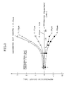
- Fig. 1 shows how a reproduction output depends on a gap length of the recording head (recording gap length).
- a gap length of the reproducing head (reproducing gap length) of 0.16 ⁇ m is used.
- 0 dB is set to a reproduction output when a gap length of the recording head is set to 0.20 ⁇ m and a reproduction output is shown by a relative value for 0 dB.
- An output improvement effect due to the recording head gap length is noticeable, especially when the gap length is 0.17 ⁇ m or less. Since the output improvement effect due to a narrow gap is larger in the higher linear recording density region, the above-explained consideration such that an decrease in magnetic transition width extracts the above result is supported.
- Fig. 2 shows how a band noise depends on the recording head gap length when a signal in which a recording wavelength is equal to 0.25 ⁇ m and a frequency is equal to 12.2 MHz according to the same measurement is recorded.
- 0 dB is set to a band noise when a recording head gap length is set to 0.10 ⁇ m and a band noise is shown by a relative value for 0 dB.
- the S/N ratio can be remarkably improved.
- the reduction effect in noises due to the narrow gap shown in Fig. 2 is caused by a fact such that noise components originated in the zigzag domain in the magnetic transition region are reduced due to the decrease in magnetic transition width.
- the noise components have a peak in a low band region near a recording wavelength of 1 ⁇ m.
- the reduction in noises is particularly effective.
- the recording head gap length is a head parameter which does not depend on the reproducing head gap length but can be independently optimally designed.
- the recording characteristics are further improved by reducing the recording head gap length so as to be smaller than 0.10 ⁇ m. In this case, it is necessary to reduce a thickness of magnetic layer of the thin film tape in accordance with the minimum magnetic reversal interval.
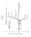
- Fig. 3 shows a dependence of the reproduction output on the reproducing head gap length.
- the recording head gap length of 0.13 ⁇ m is used.
- 0 dB is set to a reproduction output when the reproducing head gap length is set to 0.20 ⁇ m and a reproduction output is shown by a relative value for 0 dB.
- the reproducing head gap length is smaller than about 0.15 ⁇ m, the reproducing performance is deteriorated in association with a reduction in reproducing head gap length. It is considered that this is because a magnetic flux conversion efficiency is detriorated in a region of the above-mentioned narrow gap length.
- the reproducing gap length is slightly larger than the recording gap length and that in case of the example in Fig. 3, it is equal to the value from 0.15 to 0.17 ⁇ m.
- the above construction is especially effective.
- the reproducing head gap length is larger than 0.20 ⁇ m, however, the influence due to the gap loss increases, so that the output is remarkably deteriorated in the wide band from the relative low linear recording density region to the high linear recording density region. It is, therefore, undesirable.
- the recording head gap length is changed within a range of about 0.17 ⁇ m or less, in which the superior recording performance is recognized in Figs. 1 and 2, a tendency similar to that in Fig. 3 is confirmed.
- the recording head gap length is set to 0.17 mm or less and the reproducing head gap length is optimally designed so as to be larger than the recording head gap length and is equal to or less than 0.20 mm.
- the magnetic recording and reproducing apparatus in the second embodiment of the invention will now be explained.
- the second embodiment shows an apparatus made by improving that of the first embodiment.
- a saturation flux density B s of a magnetic material constructing a gap formation surface of the recording head is optimally constructed.
- the same thin film tape having a Co-O magnetic layer formed by the oblique evaporation deposition as that used in the first embodiment is used.
- the examination was performed by using six kinds of MIG type heads having different saturation flux densities of the metal soft magnetic films constructing the gap formation surfaces on the trailing edge (rear edge) side and leading edge (front edge) side as recording heads.
- Each gap length of the recording head is set to 0.10 ⁇ m on the basis of the result of the first embodiment.
- the following table 1 shows constructions of the six kinds of heads used in the second embodiment.
- Recording head B ST (T) B SL (T) A 1.0 1.0 B 1.5 1.5 C 1.3 1.0 D 1.5 1.1 E 0.7 0.7 F 1.3 0.7
- B S T and B S L denote the saturation flux densities of the metal soft magnetic films constructing the gap formation surfaces on the trailing edge (rear edge) side and the leading edge (front edge) side of the head, respectively.
- Each of three kinds of heads C, D, and F is a head having a novel construction which is different from the head with the conventional construction and in which the saturation flux density on the trailing edge (rear edge) side is set to be larger than that on the leading edge (front edge) side.
- each of the heads C, D and F can generate a head magnetic field which is asymmetry for a gap center line with an exciting current of a predetermined value or more.
- an Mn-Zn ferrite head is used as a reproducing head.
- the gap length of the reproducing head is set to 0.15 ⁇ m.
- the experiment in recording and reproducing of RF signals was made, in which a relative velocity between the head and tape is set to 3.1 m/sec, a minimum flux reversal interval on the tape is set to 0.127 ⁇ m, a flux reversal density is set to 200 kfrpi, and a band region is set to 12.2 MHz.
- Fig. 4 shows reproduction outputs in case of using various recording heads.
- 0 dB is set to a reproduction output when the recording head is set to a head A and the output is shown by a relative value for 0 dB.
- the saturation flux densities on the trailing edge and leading edge sides are the same, even when the saturation flux density is increased so as to be equal to or larger than 1.5 T, the improvement in recording performance cannot be expected further. Namely, this is because even in case of the tape having a high coercive force of 120 kA/m, the recording ability of the head with the conventional construction is saturated at a saturation flux density of about 1.0 T or more.
- a mechanism to improve the recording performance in the heads C and D is considered as follows. As already described, in the recording step of the oblique oriented thin film tape, when the gap length of the recording head is reduced, components in the easy direction of the magnetic field on the trailing edge side are steeply attenuated, so that a narrower magnetic transition width can be obtained and a high reproduction output can be obtained.
- the magnetic saturation is generated in a portion near the leading edge by an exciting current of a predetermined value or more, thereby generating the head magnetic field which is asymmetry for the gap center line and exhibits a further larger gradient on the trailing edge side than that on the leading edge side. That is, in the heads C and D in each of which the asymmetry head magnetic field is generated as mentioned above, the components in the easy direction of the head magnetic field on the trailing edge side are steeper attenuated than the case of the head B, so that a further narrower magnetic transition width can be obtained. Accordingly, the heads C and D can obtain a high reproduction output in, especially, a high linear recording density region as compared with the head B.
- noises caused by the zigzag domain in the magnetic transition region can be further reduced by the high resolution recording due to the above-mentioned mechanism.
- the saturation flux density on the trailing edge side In order to generate an asymmetry magnetic field, it is sufficient to set the saturation flux density on the trailing edge side to be larger than that on the leading edge side. In this instance, however, it is necessary to set the saturation flux density on the leading edge side to be equal to or larger than 1.0 T.
- the saturation flux density on the leading edge side is smaller than 1.0 T, the head magnetic field on the leading edge side is insufficient for the tape with a high coercive force as used in the second embodiment, so that the recording performance is deteriorated. This is the reason why the recording performance of the head F is inferior to those of the heads A and B in Fig. 4.
- the saturation flux density of the magnetic material constructing the portion near the gap of the recording head is set to 1.0 T or more and the saturation flux density of the magnetic material constructing the trailing edge is set to be larger than that of the magnetic material constructing the leading edge.
- the gap length of the recording head it is desirable to set the gap length of the recording head to about 0.17 ⁇ m or less.
- the third embodiment is made by improving the first embodiment from the viewpoint to solve the subjects.
- the third embodiment relates to the saturation flux density B S of the magnetic material constructing the gap formation surface.
- the recording head to be used in the third embodiment is characterized in that the gap formation surface is constructed by a metal soft magnetic film of a saturation flux density of 1.0 T or more and the saturation flux density of the metal soft magnetic film in a portion near an edge portion in the track width direction is larger than that in a portion near a center portion.
- the construction of the recording head is realized in a manner such that, for example, a composition gradation in the track width direction is made in the metal soft magnetic film constructing the gap formation surface, thereby setting the saturation flux density in the track edge portion to be larger than that in the center portion. It is also sufficient that the gap formation surface is constructed by a plurality of metal soft magnetic films having a laminate structure, thereby setting the saturation flux density of the metal soft magnetic film located in the track edge portion to be larger than that of the metal soft magnetic film located in the track center portion. In this instance, it is necessary to pay attention to the saturation flux density so as to be equal to or larger than 1.0 T even in the track center portion. When the saturation flux density is smaller than 1.0 T, there is a case where sufficient recording performance cannot be obtained for a high coercive force medium.
- Figs. 5 and 6 show constructional examples of a sliding surface of the recording head having the latter laminate structure.
- Fig. 5 shows an example of a sandwich type head and
- Fig. 6 shows an example of an MIG type head.
- Each head is constructed in a manner such that a first metal soft magnetic film 1 constructing a track edge portion and a second metal soft magnetic film 2 constructing a track center portion are laminated through a non-magnetic film 3.
- reference numeral 4 denotes a head gap; 5 a glass member; 6 a non-magnetic substrate; and 7 ferrite.
- Figs. 5 and 6 the examples in which the gap formation surface is constructed by a three-layer laminate film composed of two kinds of metal soft magnetic films are shown.
- the head used in the third embodiment is not limited to the example. So far as the saturation flux density in the track edge portion is larger than that in the center portion, the head can be also composed of three kinds or more of metal soft magnetic films and a laminate film in which metal soft magnetic films are laminated by four or more layers can be also used.
- the saturation flux density of the track edge portion is set to be larger than that of the center portion only on the side in which the overwriting is performed. This is because in the track edge portion on the other side to be overwritten, even when the magnetic saturation is generated and the phase deviation in the magnetic transition or the variation in the magnetic transition width is generated, the overwriting is executed by a track to be subsequently recorded, so that a problem hardly occurs.
- the track width of the recording head is smaller than the track pitch of the magnetic recording and reproducing apparatus and the recording is performed by providing a guard band between tracks, if the saturation flux densities in the both edge portions of the track are not set to be larger than that of the center portion, the effect in the third embodiment is hardly obtained.
- the laminate type recording head having the construction of Fig. 5 is mounted in the recording and reproducing apparatus used in the first and second embodiments and signals are recorded, providing guard bands onto the same thin film tape as that used in the first and second embodiments. After that, the signal pattern of the recording track is observed by a Bitter method.
- B S 1 of the recording head is set to 1.3 T and B S 2 is set to 1.0 T.
- B S 2 is set to 1.0 T.
- a gap length is set to 0.1 ⁇ m and a gap depth is set to 2 ⁇ m.
- the recording at a high magneto-motive force of 1.0 ATp-p is performed.
- Fig. 7 shows a bit pattern by the head in which both of B S 1 and B S 2 are equal to 1.0 T as a comparison example. It is recognized that a magnetic transition region 8 is curved in a track edge portion and a phase deviation occurs. In the bit pattern by the head in which B S 1 and B S 2 are equal to 1.3 T as well, the similar result is confirmed.
- Fig. 8 shows a bit pattern due to the head having the construction of the embodiment in which BS1 is equal to 1.3 T and BS2 is equal to 1.0 T.
- the curve in the magnetic transition region 8 in the track edge portion is not found and any influence by a saturation in the track edge portion of the head is not confirmed.
- reference numeral 9 denotes an inter-magnetic transition region.
- the result similar to those in the first to third embodiments can be similarly recognized.
- the recording and reproducing head the effect of the invention can be similarly obtained by using any kinds of head such as MIG type head, sandwich type head, or the like.
- the fundamental construction of the invention is not limited to those described in detail in the embodiments but it can be realized in various constructions to which the conventional technique is applied.
Landscapes
- Engineering & Computer Science (AREA)
- Manufacturing & Machinery (AREA)
- Magnetic Record Carriers (AREA)
- Recording Or Reproducing By Magnetic Means (AREA)
- Signal Processing For Digital Recording And Reproducing (AREA)
- Magnetic Heads (AREA)
Applications Claiming Priority (3)
| Application Number | Priority Date | Filing Date | Title |
|---|---|---|---|
| JP319837/95 | 1995-12-08 | ||
| JP31983795A JP3447164B2 (ja) | 1995-12-08 | 1995-12-08 | 磁気記録再生装置 |
| JP31983795 | 1995-12-08 |
Publications (3)
| Publication Number | Publication Date |
|---|---|
| EP0778562A2 EP0778562A2 (en) | 1997-06-11 |
| EP0778562A3 EP0778562A3 (en) | 1998-12-30 |
| EP0778562B1 true EP0778562B1 (en) | 2002-10-09 |
Family
ID=18114776
Family Applications (1)
| Application Number | Title | Priority Date | Filing Date |
|---|---|---|---|
| EP96119647A Expired - Lifetime EP0778562B1 (en) | 1995-12-08 | 1996-12-06 | Magnetic recording and reproducing apparatus |
Country Status (4)
| Country | Link |
|---|---|
| US (1) | US6088178A (ja) |
| EP (1) | EP0778562B1 (ja) |
| JP (1) | JP3447164B2 (ja) |
| DE (1) | DE69624204T2 (ja) |
Families Citing this family (6)
| Publication number | Priority date | Publication date | Assignee | Title |
|---|---|---|---|---|
| JP2004246949A (ja) * | 2003-02-12 | 2004-09-02 | Sony Corp | 磁気記録ヘッドと回転ドラム装置並びにこれを用いた磁気記録再生方法及び磁気記録再生装置 |
| US7414811B2 (en) * | 2005-08-26 | 2008-08-19 | International Business Machines Corporation | Magnetic head having three modules |
| US8004794B2 (en) * | 2007-08-21 | 2011-08-23 | Headway Technologies, Inc. | Perpendicular magnetic recording head laminated with AFM-FM phase change material |
| US8312609B2 (en) * | 2008-07-23 | 2012-11-20 | Seagate Technology, Llc | Method of manufacturing a patterned media stamper |
| US11508407B2 (en) * | 2018-03-30 | 2022-11-22 | Sony Corporation | Magnetic recording medium having controlled dimensional characteristics |
| JP6590106B1 (ja) * | 2019-05-08 | 2019-10-16 | ソニー株式会社 | 磁気記録媒体およびカートリッジ |
Family Cites Families (21)
| Publication number | Priority date | Publication date | Assignee | Title |
|---|---|---|---|---|
| US3956769A (en) * | 1974-08-12 | 1976-05-11 | Control Data Corporation | Recording system having coinciding servo and data tracks |
| US4313140A (en) * | 1979-12-07 | 1982-01-26 | International Business Machines Corporation | Buried control signal recording systems and method |
| JPS61214110A (ja) * | 1985-03-20 | 1986-09-24 | Hitachi Maxell Ltd | 磁気ヘツド |
| JPS6316808A (ja) * | 1986-07-09 | 1988-01-23 | Kobe Steel Ltd | 難加工材の押出し製造方法 |
| JPS6371910A (ja) * | 1986-09-16 | 1988-04-01 | Fuji Xerox Co Ltd | 記録・再生磁気ヘツド |
| NL8702779A (nl) * | 1987-11-20 | 1989-06-16 | Philips Nv | Inrichting voor het weergeven van een binair digitaal signaal, met een uitleeskop met speciaal gekozen spleetlengte. |
| US4933795A (en) * | 1987-12-07 | 1990-06-12 | Fujitsu America, Inc. | Floppy disc read and write head having two separate read and write cores for multiple track density and recording frequencies |
| JPH02168408A (ja) * | 1988-09-19 | 1990-06-28 | Hitachi Ltd | 記録再生用磁気ヘッドおよびその製造方法 |
| US4908724A (en) * | 1988-10-07 | 1990-03-13 | Eastman Kodak Company | Dual gap cross-field magnetic recording head with single gap signal excitation |
| DE3842079A1 (de) * | 1988-12-14 | 1990-06-21 | Broadcast Television Syst | Verfahren zum aufzeichnen von signalen und magnetkopfanordnung hierfuer |
| US5285331A (en) * | 1989-02-23 | 1994-02-08 | Wangtek Incorporated | System for aligning a read head gap over a track of magnetic data |
| JPH02265001A (ja) * | 1989-04-04 | 1990-10-29 | Matsushita Electric Ind Co Ltd | 磁気記録再生装置 |
| JPH02310818A (ja) * | 1989-05-24 | 1990-12-26 | Toshiba Corp | データ記録再生装置のヘッド装置及びヘッド位置決め制御装置 |
| US5155645A (en) * | 1989-11-14 | 1992-10-13 | Sanyo Electric Co., Ltd. | Magnetic head with improved efficiency in both high and low frequency ranges |
| DE69123487T2 (de) * | 1990-05-31 | 1997-06-26 | Sony Corp | Dünnfilmmagnetkopf |
| US5132859A (en) * | 1990-08-23 | 1992-07-21 | International Business Machines Corporation | Thin film structures for magnetic recording heads |
| JPH04251405A (ja) * | 1990-12-29 | 1992-09-07 | Pioneer Electron Corp | 磁気記録再生装置 |
| US5309306A (en) * | 1991-06-10 | 1994-05-03 | Mitsubishi Denki Kabushiki Kaisha | Complex magnetic head |
| US5492774A (en) * | 1991-07-23 | 1996-02-20 | Sony Corporation | Perpendicular magnetic recording medium and process for production of the same |
| JP3393491B2 (ja) * | 1991-07-23 | 2003-04-07 | ソニー株式会社 | 垂直磁気記録媒体及びその製造方法 |
| JPH05234058A (ja) * | 1991-12-28 | 1993-09-10 | Sony Corp | 磁気記録媒体及び磁気記録再生装置 |
-
1995
- 1995-12-08 JP JP31983795A patent/JP3447164B2/ja not_active Expired - Fee Related
-
1996
- 1996-12-06 US US08/760,452 patent/US6088178A/en not_active Expired - Fee Related
- 1996-12-06 EP EP96119647A patent/EP0778562B1/en not_active Expired - Lifetime
- 1996-12-06 DE DE69624204T patent/DE69624204T2/de not_active Expired - Fee Related
Also Published As
| Publication number | Publication date |
|---|---|
| EP0778562A3 (en) | 1998-12-30 |
| US6088178A (en) | 2000-07-11 |
| DE69624204D1 (de) | 2002-11-14 |
| JP3447164B2 (ja) | 2003-09-16 |
| EP0778562A2 (en) | 1997-06-11 |
| DE69624204T2 (de) | 2003-02-20 |
| JPH09161202A (ja) | 1997-06-20 |
Similar Documents
| Publication | Publication Date | Title |
|---|---|---|
| US5224002A (en) | Thin-film magnetic head device | |
| US5126907A (en) | Thin film magnetic head having at least one magnetic core member made at least partly of a material having a high saturation magnetic flux density | |
| JPS5891B2 (ja) | 磁気記録媒体 | |
| JP2597967B2 (ja) | 磁気記録媒体 | |
| EP0778562B1 (en) | Magnetic recording and reproducing apparatus | |
| US5347408A (en) | Magnetic recording and reproducing method and apparatus with vertical magnetization component reduction | |
| JPH10320720A (ja) | 垂直記録用磁気ヘッド | |
| US5276575A (en) | Magnetic head having a notched magnetic core portion with a zero depth position offset | |
| Luitjens et al. | High bit density (100 Mb/cm/sup 2/) with single-layer Co-Cr media and ring heads in perpendicular magnetic recording | |
| US5155645A (en) | Magnetic head with improved efficiency in both high and low frequency ranges | |
| JPH046602A (ja) | 磁気ヘッド | |
| JPH06139542A (ja) | 垂直磁気記録媒体 | |
| EP0415335B1 (en) | Magnetic recording medium | |
| EP0431633A2 (en) | Magnetic transducer head for narrow track width recording | |
| JP2725506B2 (ja) | 磁気記録媒体 | |
| KR100246223B1 (ko) | 복합형 자기 헤드 | |
| YOSHIDA et al. | Digital recording characteristics of Co-O thin film with carbon protective layer | |
| JP3039033B2 (ja) | 垂直磁気記録再生方法 | |
| TAGAMI et al. | R/W characteristics of perpendicular magnetic recording | |
| JPH05205216A (ja) | 磁気ヘッド | |
| JPH05101310A (ja) | 磁気記録方法 | |
| Tsunki et al. | Development of a consumer VCR format and a high-density magnetic recording using an MR head | |
| JPH11203620A (ja) | 磁気ヘッド | |
| JPH05343225A (ja) | 磁気記録媒体 | |
| JPH0447365B2 (ja) |
Legal Events
| Date | Code | Title | Description |
|---|---|---|---|
| PUAI | Public reference made under article 153(3) epc to a published international application that has entered the european phase |
Free format text: ORIGINAL CODE: 0009012 |
|
| AK | Designated contracting states |
Kind code of ref document: A2 Designated state(s): DE FR GB |
|
| PUAL | Search report despatched |
Free format text: ORIGINAL CODE: 0009013 |
|
| AK | Designated contracting states |
Kind code of ref document: A3 Designated state(s): DE FR GB |
|
| 17P | Request for examination filed |
Effective date: 19981229 |
|
| 17Q | First examination report despatched |
Effective date: 19990510 |
|
| GRAG | Despatch of communication of intention to grant |
Free format text: ORIGINAL CODE: EPIDOS AGRA |
|
| GRAG | Despatch of communication of intention to grant |
Free format text: ORIGINAL CODE: EPIDOS AGRA |
|
| GRAH | Despatch of communication of intention to grant a patent |
Free format text: ORIGINAL CODE: EPIDOS IGRA |
|
| GRAH | Despatch of communication of intention to grant a patent |
Free format text: ORIGINAL CODE: EPIDOS IGRA |
|
| GRAA | (expected) grant |
Free format text: ORIGINAL CODE: 0009210 |
|
| AK | Designated contracting states |
Kind code of ref document: B1 Designated state(s): DE FR GB |
|
| REG | Reference to a national code |
Ref country code: GB Ref legal event code: FG4D |
|
| REF | Corresponds to: |
Ref document number: 69624204 Country of ref document: DE Date of ref document: 20021114 |
|
| ET | Fr: translation filed | ||
| PLBE | No opposition filed within time limit |
Free format text: ORIGINAL CODE: 0009261 |
|
| STAA | Information on the status of an ep patent application or granted ep patent |
Free format text: STATUS: NO OPPOSITION FILED WITHIN TIME LIMIT |
|
| 26N | No opposition filed |
Effective date: 20030710 |
|
| PGFP | Annual fee paid to national office [announced via postgrant information from national office to epo] |
Ref country code: GB Payment date: 20071205 Year of fee payment: 12 Ref country code: FR Payment date: 20071210 Year of fee payment: 12 |
|
| PGFP | Annual fee paid to national office [announced via postgrant information from national office to epo] |
Ref country code: DE Payment date: 20071129 Year of fee payment: 12 |
|
| GBPC | Gb: european patent ceased through non-payment of renewal fee |
Effective date: 20081206 |
|
| REG | Reference to a national code |
Ref country code: FR Ref legal event code: ST Effective date: 20090831 |
|
| PG25 | Lapsed in a contracting state [announced via postgrant information from national office to epo] |
Ref country code: DE Free format text: LAPSE BECAUSE OF NON-PAYMENT OF DUE FEES Effective date: 20090701 |
|
| PG25 | Lapsed in a contracting state [announced via postgrant information from national office to epo] |
Ref country code: GB Free format text: LAPSE BECAUSE OF NON-PAYMENT OF DUE FEES Effective date: 20081206 |
|
| PG25 | Lapsed in a contracting state [announced via postgrant information from national office to epo] |
Ref country code: FR Free format text: LAPSE BECAUSE OF NON-PAYMENT OF DUE FEES Effective date: 20081231 |