EP0773075A2 - Verfahren und vorrichtung zur regelung überprüfung oder optimierung des zylinderstiftendrucks einer presse durch flüssigkeits oder anfangsdruckausstoss - Google Patents
Verfahren und vorrichtung zur regelung überprüfung oder optimierung des zylinderstiftendrucks einer presse durch flüssigkeits oder anfangsdruckausstoss Download PDFInfo
- Publication number
- EP0773075A2 EP0773075A2 EP97200413A EP97200413A EP0773075A2 EP 0773075 A2 EP0773075 A2 EP 0773075A2 EP 97200413 A EP97200413 A EP 97200413A EP 97200413 A EP97200413 A EP 97200413A EP 0773075 A2 EP0773075 A2 EP 0773075A2
- Authority
- EP
- European Patent Office
- Prior art keywords
- pressure
- hydraulic pressure
- blank
- hydraulic
- initial
- Prior art date
- Legal status (The legal status is an assumption and is not a legal conclusion. Google has not performed a legal analysis and makes no representation as to the accuracy of the status listed.)
- Granted
Links
Images


Classifications
-
- G—PHYSICS
- G01—MEASURING; TESTING
- G01L—MEASURING FORCE, STRESS, TORQUE, WORK, MECHANICAL POWER, MECHANICAL EFFICIENCY, OR FLUID PRESSURE
- G01L5/00—Apparatus for, or methods of, measuring force, work, mechanical power, or torque, specially adapted for specific purposes
- G01L5/0061—Force sensors associated with industrial machines or actuators
- G01L5/0076—Force sensors associated with manufacturing machines
-
- B—PERFORMING OPERATIONS; TRANSPORTING
- B21—MECHANICAL METAL-WORKING WITHOUT ESSENTIALLY REMOVING MATERIAL; PUNCHING METAL
- B21D—WORKING OR PROCESSING OF SHEET METAL OR METAL TUBES, RODS OR PROFILES WITHOUT ESSENTIALLY REMOVING MATERIAL; PUNCHING METAL
- B21D24/00—Special deep-drawing arrangements in, or in connection with, presses
- B21D24/04—Blank holders; Mounting means therefor
- B21D24/08—Pneumatically or hydraulically loaded blank holders
-
- B—PERFORMING OPERATIONS; TRANSPORTING
- B21—MECHANICAL METAL-WORKING WITHOUT ESSENTIALLY REMOVING MATERIAL; PUNCHING METAL
- B21D—WORKING OR PROCESSING OF SHEET METAL OR METAL TUBES, RODS OR PROFILES WITHOUT ESSENTIALLY REMOVING MATERIAL; PUNCHING METAL
- B21D24/00—Special deep-drawing arrangements in, or in connection with, presses
- B21D24/10—Devices controlling or operating blank holders independently, or in conjunction with dies
- B21D24/14—Devices controlling or operating blank holders independently, or in conjunction with dies pneumatically or hydraulically
-
- B—PERFORMING OPERATIONS; TRANSPORTING
- B30—PRESSES
- B30B—PRESSES IN GENERAL
- B30B1/00—Presses, using a press ram, characterised by the features of the drive therefor, pressure being transmitted directly, or through simple thrust or tension members only, to the press ram or platen
- B30B1/26—Presses, using a press ram, characterised by the features of the drive therefor, pressure being transmitted directly, or through simple thrust or tension members only, to the press ram or platen by cams, eccentrics, or cranks
- B30B1/265—Presses, using a press ram, characterised by the features of the drive therefor, pressure being transmitted directly, or through simple thrust or tension members only, to the press ram or platen by cams, eccentrics, or cranks using a fluid connecting unit between drive shaft and press ram
-
- B—PERFORMING OPERATIONS; TRANSPORTING
- B30—PRESSES
- B30B—PRESSES IN GENERAL
- B30B15/00—Details of, or accessories for, presses; Auxiliary measures in connection with pressing
- B30B15/0029—Details of, or accessories for, presses; Auxiliary measures in connection with pressing means for adjusting the space between the press slide and the press table, i.e. the shut height
- B30B15/0035—Details of, or accessories for, presses; Auxiliary measures in connection with pressing means for adjusting the space between the press slide and the press table, i.e. the shut height using an adjustable connection between the press drive means and the press slide
-
- B—PERFORMING OPERATIONS; TRANSPORTING
- B30—PRESSES
- B30B—PRESSES IN GENERAL
- B30B15/00—Details of, or accessories for, presses; Auxiliary measures in connection with pressing
- B30B15/0094—Press load monitoring means
-
- B—PERFORMING OPERATIONS; TRANSPORTING
- B30—PRESSES
- B30B—PRESSES IN GENERAL
- B30B15/00—Details of, or accessories for, presses; Auxiliary measures in connection with pressing
- B30B15/14—Control arrangements for mechanically-driven presses
-
- B—PERFORMING OPERATIONS; TRANSPORTING
- B30—PRESSES
- B30B—PRESSES IN GENERAL
- B30B15/00—Details of, or accessories for, presses; Auxiliary measures in connection with pressing
- B30B15/28—Arrangements for preventing distortion of, or damage to, presses or parts thereof
- B30B15/281—Arrangements for preventing distortion of, or damage to, presses or parts thereof overload limiting devices
Definitions
- the present invention relates in general to a cushioning apparatus for applying a uniform cushioning force or a blank-holding force to a blank to be processed on a press, and more particularly to such cushioning apparatus capable of changing the force applied to hold the blank during a pressing operation on the workpiece, a method of checking or determining an optimum condition relating to a hydraulic pressure of the cushioning apparatus for uniform distribution of the blank-holding force, and a device for determining or establishing such optimum condition.
- a press has a press slide with an upper die attached thereto, which is lowered toward a lower die to perform a pressing operation on a blank or workpiece between the upper and lower dies while the blank is held by and between the upper die and a pressure member such as a pressure ring.
- a cushioning apparatus which includes (a) a cushion platen biased in an upward direction with a predetermined biasing force by suitable force generating means, (b) a plurality of balancing hydraulic cylinders disposed on the cushion platen and having respective fluid chambers which communicate with each other, and (c) a plurality of cushion pins linked at their lower ends with the respective hydraulic cylinders and supporting at their upper ends the pressure member, so that a blank-holding force (cushioning force) corresponding to the biasing force generated by the force generating means is applied to the pressure member through the cushion platen, hydraulic cylinders and cushion pins.
- the balancing hydraulic cylinders function to assure uniform distribution of the blank-holding force on the cushion pins, that is, permit the blank-holding force to be transmitted to the blank such that substantially equal components of the force act on all the cushion pins.
- the force generating means for generating the blank-holding force to be applied to the pressure member has a combination of a cushioning pneumatic cylinder and a cushioning hydraulic cylinder whose pistons are integrally connected in series with each other.
- the cushioning hydraulic cylinder is connected to a pressure relief valve, through which the pressurized fluid is discharged from the hydraulic cylinder when the hydraulic pressure exceeds a controllable relief pressure.
- the blank-holding force generated by the force generating means is determined by the pressure of the compressed air supplied to the pneumatic cylinder and the relief pressure of the pressure relief valve.
- the relief pressure of the relief valve is controlled by a controller, to change the blank-holding force.
- This cushioning apparatus having such force generating means and controller is capable of effecting fine or intricate adjustment of the blank-holding force during a pressing operation, namely, during a downward movement of the press slide after the upper die contacts the blank to start an effective pressing stroke down to the lower stroke end.
- the fine adjustment of the blank-holding force permits reduction in the vibration of the blank upon abutting contact of the upper die with the pressure member, and is effective to prevent an excessive amount of initial movement of the blank between the pressure member and the upper die due to the vibration, thereby assuring comparatively improved surface quality of the article produced from the blank.
- the present arrangement makes it possible to reduce the blank-holding force during a pressing action on the blank to thereby protect the blank from rupture, whereby the material grade of the blank may be lowered to reduce the material cost.
- the cushioning apparatus having the force generating means and the controller arranged as described above not only assures even distribution of the blank-holding force on the pressure member (blank), but also provides other advantages for enhanced results of the pressing operation on the blank.
- the above cushioning apparatus having the cushioning pneumatic and hydraulic cylinders as the force generating means capable of controlling the blank-holding force requires two hydraulic circuits, one for the balancing hydraulic cylinders associated with the cushion pins, and the other for the cushioning hydraulic cylinder of the force generating means for generating the blank-holding force. Accordingly, the apparatus tends to be complicated and expensive. Although the cost of the force generating means and the controller is comparatively low if they are incorporated in a cushioning apparatus upon manufacture of the apparatus, the application of these force generating means and controller to the existing cushioning apparatus requires considerable modification of the apparatus, which increases the overall cost of the apparatus to such a high level that cannot justify the practical utilization of such force generating means and controller for the existing cushioning apparatus.
- the average operating stroke Xav of the pistons of the balancing hydraulic cylinders is predetermined by experiments, for example, so as to enable all the cushion pins to abut at their upper ends on the pressure member while the pistons of the hydraulic cylinders are spaced away from their upper stroke ends by the cushion pins, but do not reach their lower stroke ends due to collision of the upper die with the pressure member through the blank during a pressing action on the blank, even if the cushion pins have different length dimensions and the cushion platen is inclined with respect to the horizontal plane.
- the total fluid volume V is a total volume of the working fluid in the fluid chambers of all the hydraulic cylinders when the pistons are at their upper ends, plus a volume of the fluid in the hydraulic circuit connected to the hydraulic cylinders.
- the optimum initial hydraulic pressure Po determined so as to satisfy the above equation (1) basically permits the pistons of the hydraulic cylinders to be lowered from their upper stroke ends by an average distance equal to Xav, during a pressing action on the blank, so that the blank-holding force is substantially evenly distributed on the pressure members through the cushion pins.
- the volume modulus of elasticity K of the fluid varies due to air introduced into the fluid or deterioration of the fluid. Therefore, the optimum initial hydraulic pressure Po calculated according to the above equation (1) is not necessarily accurate.
- the values obtained by the cumbersome experiments may include some errors, which lead to errors in the calculated optimum values Po and PXo, resulting in the failure to establish uniform distribution of the blank-holding force and the surface pressure on the pressure member, even if the actual initial and in-process pressure values P and PX are adjusted to the calculated optimum values Po and PXo.
- the article produced from the blank may be defective.
- Another proposed approach to improve the quality of the produced article is to compare the actual in-process hydraulic pressure PX with the optimum value PXo obtained as described above, to thereby monitor the distribution of the blank-holding force on the pressure member.
- the comparison of the values PX and PXo does not allow accurate checking of the uniform distribution of the blank-holding force.
- the present invention was made in view of the prior art discussed above.
- a second object of this invention is to provide a method by which an optimum hydraulic pressure condition of the cushioning apparatus such as the optimum initial and in-process hydraulic pressure values of the balancing hydraulic cylinders can be easily and accurately checked or determined so as to establish uniform distribution of the blank-holding force on the pressure member through the cushion pins.
- a third object of the invention is to provide a device capable of easily and accurately determining or establishing such optimum hydraulic pressure condition of the cushioning apparatus.
- the first object indicated above may be achieved according to a first object of the present invention, which provides a cushioning apparatus for a press having an upper die and a lower die which cooperate to perform a pressing action on a blank during a downward movement of the upper die, and a pressure member which cooperates with the upper die to hold the blank during the pressing action, the cushioning apparatus including (a) force generating means for generating a biasing force, (b) a cushion platen disposed below the lower die and biased toward the lower die by the biasing force, (c) a plurality of balancing hydraulic cylinders disposed on the cushion platen and having fluid chambers communicating with each other, and (d) a plurality of cushion pins associated at lower ends thereof with the hydraulic cylinders, respectively, and supporting at upper ends thereof the pressure member, and wherein the blank is held by the upper die and the pressure member during the pressing action, by a blank-holding force corresponding to the biasing force which is transmitted to the pressure member through the hydraulic cylinders and cushion pins such that the biasing force
- the blank-holding force to be applied to the pressure member to hold the blank is basically determined by the biasing force generated by the force generating means of the cushioning apparatus. If the fluid is partially discharged from the balancing hydraulic cylinders during a pressing action in which the cushion platen, hydraulic cylinders and cushion pins are lowered as a unit, the pressure in the hydraulic cylinders is temporarily lowered due to the inertia of those components, whereby the blank-holding force is accordingly decreased.
- the amount of decrease of the blank-holding force varies with the rate of discharge of the fluid from the hydraulic cylinders. When the fluid discharge from the hydraulic cylinders is stopped during the pressing action, the blank-holding force will rise back to the original level determined by the biasing force of the force generating means.
- the blank-holding force can be controlled or changed as needed during the pressing action, by controlling the flow regulating means provided in the discharge line, to permit the fluid to be discharged from the hydraulic cylinders through the flow regulating means according to a predetermined pattern of change in the flow rate in relation to the downward movement of the upper die during the pressing action, whereby the pressure in the hydraulic cylinders is changed according to a pattern corresponding to the pattern of change in the rate of the discharge flow of the fluid.
- the present cushioning apparatus is capable of adjusting the blank-holding force during a pressing action by partially discharging the pressurized fluid from the balancing hydraulic cylinders whose primary function is to establish even distribution of the blank-holding force. Accordingly, the apparatus according to the present invention does not require a cushioning hydraulic cylinder conventionally used in combination with a cushioning pneumatic cylinder to provide the force generating means.
- the conventionally used cushioning hydraulic cylinder is connected to a pressure relief valve to control the blank-holding force. In the absence of such cushioning hydraulic cylinder and the pressure relief valve connected to that cushioning hydraulic cylinder, the present cushioning apparatus is comparatively simple and available at a reduced cost.
- the present cushioning apparatus may be easily provided on an existing press, by simply connecting the discharge line to the fluid chambers of the balancing hydraulic cylinders, and providing the flow regulating means in the discharge line so that the flow rate of the flow regulating means is controlled by the controller in relation to the vertical position of the upper die during the pressing action.
- the present apparatus is available on the existing press without considerable modifications of the press.
- the first object indicated above may also be achieved according to a second aspect of this invention, which provides a cushioning apparatus for a press having an upper die and a lower die which cooperate to perform a pressing action on a blank during a downward movement of the upper die, and a pressure member which cooperates with the upper die to hold the blank during the pressing action, the cushioning apparatus including (a) force generating means for generating a biasing force, (b) a cushion platen disposed below the lower die and biased toward the lower die by the biasing force, (c) a plurality of hydraulic cylinders disposed on the cushion platen, and (d) a plurality of cushion pins associated at lower ends thereof with the hydraulic cylinders, respectively, and supporting at upper ends thereof the pressure member, and wherein the blank is held by the upper die and the pressure member during the pressing action, by a blank-holding force corresponding to the biasing force which is transmitted to the pressure member through the hydraulic cylinders and cushion pins such that the biasing force is substantially evenly distributed on all of the cushion pins by
- the pressurized fluid is supplied to the plurality of groups of hydraulic cylinders through the respective mutually independent supply lines, while the plurality of groups of hydraulic cylinders are connected to the respective discharge lines so that the discharge flows of the fluid from the plurality of groups of hydraulic cylinders through the corresponding discharge lines are controlled independently of each other by the respective flow regulating means which are provided in the respective discharge lines and which are controlled independently of each other by the control means, to control the pressure values of the fluid in the respective groups of hydraulic cylinders according to the predetermined patterns of change in the pressure values in relation to the downward movement of the upper die during the pressing action.
- the local blank-holding force values acting on the local portions of the pressure member corresponding to the two or groups of hydraulic cylinders can be intricately controlled independently of each other, namely, can be adjusted to different values, by suitably controlling the rates of the discharge flows of the fluid through the respective flow regulating means, depending upon the specific configuration and specifications of the blank and varying degrees of wear at the local portions of the die set which includes the upper die, lower die and pressure member.
- the second object indicated above may be achieved according to a third aspect of this invention, which provides a method of checking an optimum condition relating to a hydraulic pressure of a plurality of hydraulic cylinders in a cushioning apparatus for a press having an upper die and a lower die which cooperate to perform a pressing action on a blank during a downward movement of the upper die, and a pressure member which cooperates with the upper die to hold the blank during the pressing action,
- the cushioning apparatus including (a) force generating means for generating a blank-holding force, (b) a cushion platen disposed below the lower die and biased toward the lower die by the blank-holding force, (c) the plurality of hydraulic cylinders disposed on the cushion platen and having fluid chambers communicating with each other, and (d) a plurality of cushion pins associated at lower ends thereof with the hydraulic cylinders, respectively, and supporting at upper ends thereof the pressure member, and wherein the blank is held by the upper die and the pressure member during the pressing action, by the blank-holding force which is generated by the
- the graph of Fig. 17 indicates a relationship between the initial hydraulic pressure in the hydraulic cylinders prior to a pressing action on the blank and the in-process hydraulic pressure during the pressing action. This relationship is obtained by changing the initial hydraulic pressure while the other operating conditions of the press such as the blank-holding force are held constant.
- the initial hydraulic pressure is in a high range A
- the pistons of all the hydraulic cylinders are kept stationary while being held in their upper stroke ends, as indicated in Fig. 17.
- the pistons of some of the hydraulic cylinders corresponding to the relatively long cushion pins are slightly moved downward away from their upper stroke ends, while the pistons of the other hydraulic cylinders corresponding to the relatively short cushion pins are still held at their upper stroke ends.
- the blank-holding force is not perfectly evenly distributed on all the cushion pins.
- the initial hydraulic pressure of the hydraulic cylinders is lowered, the average distance of downward movements of the pistons of the cylinders increases, thereby increasing the number of the cylinders whose pistons are moved downward away from the upper stroke ends, whereby the blank-holding force is distributed to those cylinders and the corresponding cushion pins. Accordingly, the in-process hydraulic pressure of the cylinders during the pressing action is lowered as the initial hydraulic pressure is lowered within the range B.
- the bottomed pistons will cause the blank-holding force to be transmitted directly to the corresponding cushion pins without the cushioning effect of the hydraulic pressure. As the initial hydraulic pressure is lowered, the number of the bottomed pistons increases, and the in-process hydraulic pressure is accordingly lowered.
- all the hydraulic cylinders provided on the cushion platen are not necessarily or always placed in their operable states or used to effectively act to transmit the blank-holding force to the pressure member, but some of the hydraulic cylinders may be held in their inoperable states as needed.
- all the hydraulic cylinders as defined above with respect to the optimum range C should be interpreted to mean all the hydraulic cylinders which are placed in their operable states and whose pistons are moved downward away from their upper stroke ends through the corresponding cushion pins during a pressing action on the blank, and contribute to the distribution of the blank-holding force to the pressure member.
- the cushion pins have an excessively large variation in the length dimension, or if the operating strokes of some of the cylinder pistons are excessively small, there may arise a situation in which some of the cylinder pistons are held at their upper stroke ends while the other cylinder pistons are bottomed (held at their lower stroke ends). In this case, it is possible that the optimum range C of the initial hydraulic value as defined above cannot be recognized or cannot be clearly determined, or two or more optimum ranges are recognized. In such situation, therefore, some abnormality exists in the cushioning apparatus.
- the optimum range (indicated at C in Fig. 17) in which the in-process hydraulic pressure is held substantially constant even with a change in the initial hydraulic pressure can be determined, recognized or detected on the basis of the relationship between the initial and in-process values of the hydraulic pressure, which relationship is obtained by detecting the in-process value while the initial value is changed.
- the thus determined optimum range C of the initial hydraulic pressure can be used to determine the optimum condition relating to the hydraulic pressure of the hydraulic cylinders, namely, the optimum initial pressure and/or the optimum in-process pressure of the hydraulic cylinders which permit substantially even or uniform distribution of the blank-holding force to all the cushion pins.
- an initial hydraulic pressure value selected within the determined optimum range C may be used as an optimum initial pressure Po prior to a pressing action, which permits the blank-holding force to be evenly distributed to all the cushion pins.
- the initial hydraulic pressure to the optimum initial value Po prior to the pressing operation the distribution of the surface pressure of the pressure member during the pressing action can be made substantially constant over the entire working area of the pressure member.
- the in-process hydraulic pressure value corresponding to the optimum initial pressure value Po is an optimum in-process hydraulic pressure PXo during the pressing action. Consequently, the initial hydraulic pressure may be finely adjusted so that the actual in-process hydraulic pressure substantially coincides with the optimum value PXo.
- inadequate pressing conditions due to some abnormality of the hydraulic cylinders can be detected by monitoring the actual in-process hydraulic pressure for substantial coincidence with the optimum value PXo. It is also possible to obtain the actual blank-holding force from the determined optimum in-process pressure value PXo. If the optimum range of the initial hydraulic pressure cannot be determined or recognized, this information can be used to provide an indication that the cushioning apparatus suffers from some abnormality.
- the method according to the third aspect of the invention permits easy and accurate determination or diagnosis of the optimum condition relating to the hydraulic pressure of the hydraulic cylinders, without the conventionally required calculation according to the above equations (1) or (2) on the basis of the average operating stroke Xav and pressure-receiving area As of the pistons of the hydraulic cylinders, and volume modulus of elasticity K and total volume V of the working fluid.
- the second object indicated above may also be achieved according to a fourth aspect of the present invention, which provides a method of checking an optimum condition relating to a hydraulic pressure of a plurality of hydraulic cylinders in a cushioning apparatus for a press having an upper die and a lower die which cooperate to perform a pressing action on a blank during a downward movement of the upper die, and a pressure member which cooperates with the upper die to hold the blank during the pressing action,
- the cushioning apparatus including (a) force generating means for generating a blank-holding force, (b) a cushion platen disposed below the lower die and biased toward the lower die by the blank-holding force, (c) the plurality of hydraulic cylinders disposed on the cushion platen and having fluid chambers communicating with each other, and (d) a plurality of cushion pins associated at lower ends thereof with the hydraulic cylinders, respectively, and supporting at upper ends thereof the pressure member, and wherein the blank is held by the upper die and the pressure member during the pressing action, by the blank-holding force which is generated
- Changing the amount of the working fluid in the hydraulic circuit including the hydraulic cylinders has substantially the same significance as changing the initial hydraulic pressure in the hydraulic cylinders prior to a pressing action in the method according to the third aspect of the invention. That is, when the hydraulic pressure in the hydraulic cylinders is held within an optimum range permitting substantially even distribution of the blank-holding force, the fluid pressure in the hydraulic circuit is substantially constant, irrespective of a change in the amount of the fluid in the hydraulic circuit, which causes only slight movements of the pistons of the hydraulic cylinders.
- the present method is formulated to first lower the upper die to the predetermined blank-holding position such as its lower stroke end, change the amount of the fluid in the hydraulic circuit communicating with the hydraulic cylinders while the upper die is held in the blank-holding position, and detect the pressure of the fluid while the fluid amount is changed.
- the range of the fluid pressure in which the fluid pressure is substantially constant irrespective of a change in the fluid amount in the hydraulic circuit may be determined as an optimum range of the fluid pressure that should be established during a pressing action. Therefore, the above-indicated optimum hydraulic pressure PXo of the hydraulic cylinders can be selected within the determined optimum range.
- the initial pressure of the hydraulic cylinders can be adjusted to an optimum level so that the actual in-process hydraulic pressure during a pressing action is substantially equal to the determined optimum value PXo.
- the in-process hydraulic pressure may be compared with the determined optimum value PXo, to monitor the pressing condition for any abnormality which may arise due to entry of any foreign matters in the hydraulic cylinders.
- the optimum in-process hydraulic pressure PXo may be used to obtain the desired blank-holding force. If the optimum range of the fluid pressure in the hydraulic circuit cannot be determined or detected, this means the existence of some abnormality in the cushioning apparatus, which may be indicated by suitable alarm means.
- the method according to the fourth aspect of this invention as described above also permits easy and accurate determination of the optimum condition relating to the hydraulic pressure of the hydraulic cylinders, and diagnosis of the cushioning apparatus, without the conventionally required calculation according to the above equation (1) or (2) on the basis of the operating parameters of the apparatus such as the average operating stroke Xav and pressure-receiving area As of the pistons of the cylinders, and the volume modulus of elasticity K and total volume V of the working fluid in the hydraulic circuit.
- the operation to determine the optimum hydraulic pressure condition can be readily and efficiently performed in a fully automatic manner, unlike the operation according to the third aspect of the invention in which the in-process hydraulic pressure values are detected with different initial hydraulic pressure values that are established in different test pressing cycles.
- the third object may be achieved according to a fifth aspect of this invention, which provides an device for determining an optimum condition relating to a hydraulic pressure of a plurality of hydraulic cylinders in a cushioning apparatus for a press having an upper die and a lower die which cooperate to perform a pressing action on a blank during a downward movement of the upper die, and a pressure member which cooperates with the upper die to hold the blank during the pressing action,
- the cushioning apparatus including (a) force generating means for generating a blank-holding force, (b) a cushion platen disposed below the lower die and biased toward the lower die by the blank-holding force, (c) the plurality of hydraulic cylinders disposed on the cushion platen and having fluid chambers communicating with each other, and (d) a plurality of cushion pins associated at lower ends thereof with the hydraulic cylinders, respectively, and supporting at upper ends thereof the pressure member, and wherein the blank is held by the upper die and the pressure member during the pressing action, by the blank-holding force which is generated by the force
- the in-process values of the hydraulic pressure of the hydraulic cylinders during a pressing action on the blank are detected by the detecting means while the initial value of the hydraulic pressure is changed by the initial pressure changing means.
- the amount of change of the successively detected in-process pressure values corresponding to the different initial pressure values is calculated by the calculating means.
- the judging means judges whether the calculated amount of change is larger than a predetermined value or not, that is, determines whether the in-process pressure value is substantially constant irrespective of a change in the initial pressure value. If the calculated amount of change is determined not to be larger than the predetermined value, the corresponding initial pressure value is determined to fall within an optimum range of the initial pressure. This determination is effected each time the initial pressure value is changed.
- the determining means determines the optimum operating condition relating to the pressure of the hydraulic cylinders, for instance, the optimum initial hydraulic pressure Po and/or the optimum in-process hydraulic pressure PXo.
- the optimum initial hydraulic pressure Po selected within the optimum range permits even distribution of the blank-holding force to all the cushion pins.
- the optimum in-process hydraulic pressure PXo corresponds to the initial pressure value selected within the optimum range.
- the initial hydraulic pressure may be finely adjusted so that the actual in-process hydraulic pressure substantially coincides with the optimum value PXo. Further, inadequate pressing conditions due to some abnormality of the hydraulic cylinders (e.g., due to foreign matters trapped within the cylinders) can be detected by monitoring the actual in-process hydraulic pressure for substantial coincidence with the optimum value PXo.
- the device is capable of determining the optimum condition relating to the hydraulic pressure of the hydraulic cylinders, according to the principle of the method according to the third aspect of the invention.
- the initial pressure changing means for changing the initial pressure value and the detecting means for detecting the in-process pressure value while the initial pressure value is changed correspond to the detecting step of the method.
- the calculating means for calculating the amount of change in the in-process pressure value and the judging means for judging whether the amount of change is larger than the predetermined value corresponds to the determining step of the method.
- the present device is also capable of easily and accurately determining the optimum hydraulic pressure condition of the hydraulic cylinders, without the conventionally required calculation according to the above equation (1) or (2) on the basis of the average operating stroke Xav and pressure-receiving area As of the hydraulic cylinder pistons and the volume modulus of elasticity K and total volume V of the working fluid. Accordingly, the present device is effective to reduce defects of the product obtained by the pressing action on the blank.
- the operator's load can be reduced, and the erroneous setting of the operating conditions of the press due to erroneous manipulation of the press can be effectively avoided, since the device is adapted to automate the detection of the hydraulic pressure, calculation of the amount of change in the detected pressure, determination on the optimum range of the initial pressure, and determination of the optimum hydraulic pressure condition on the basis of the determined optimum range.
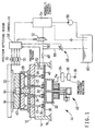
- a lower die in the form of a punch 10 is mounted on a bolster 12 disposed on a carrier 14 resting on a machine base 16, while an upper die 18 is carried by a press slide 20 which is vertically reciprocated by a drive mechanism including a drive motor, cranks and links, as well known in the art.
- the bolster 12 has a multiplicity of through-holes 24 through which respective cushion pins 22 extend in the direction of reciprocation of the press slide 20.
- the cushion pins 22 are supported at their lower ends by a cushion platen 26 disposed below the bolster 12.
- the cushion pins 22 are provided to support, at their upper ends, a pressure member in the form of a pressure ring 28 which is disposed so as to surround the working portion of the punch 10.
- the number of the cushion pins 22 and their positions relative to the pressure ring 28 are determined as needed depending upon the size and configuration of the pressure ring 28.
- the cushion platen 26 is provided with a multiplicity of balancing hydraulic cylinders 30 disposed thereon in alignment with the through-holes 24 formed through the bolster 12.
- the hydraulic cylinders 30 have housings secured to the upper surface of the cushion platen 26, and pistons which are held in abutting contact with the lower end faces of the respective cushion pins 22.
- the punch 10, die 18 and pressure ring 28 serve as the lower die, upper die and pressure member, respectively.
- the cushion platen 26 is disposed within the press carrier 14 and supported by a cushioning pneumatic cylinder 32, such that the platen 26 is movable in the direction of reciprocation of the press slide 20, and biased by the pneumatic cylinder 32 in the upward direction.
- the pneumatic cylinder 32 has an air chamber communicating with an air tank 34 which stores compressed air having a pneumatic pressure Pa supplied from an air pressure source 36 via a pneumatic pressure regulator 38.
- the pneumatic pressure Pa is determined and adjusted depending upon a desired blank-holding force to be applied to the pressure ring 28.
- a blank 40 in the form of a metal strip to be drawn into an intended article is placed on the pressure ring 28 before a pressing or drawing operation on the blank 40 is started with a downward movement of the press slide 20 with the upper die 18.
- the upper die 18 forces an outer portion of the blank 40 against the pressure ring, whereby the blank 40 is held in place prior to a drawing action on the blank 40 between the upper and lower dies 18, 10.
- the pneumatic cylinder 32 is pressed down via the pressure ring 28, cushion pins 22, hydraulic cylinders 30 and cushion platen 26, whereby a reaction force corresponding to the pneumatic pressure Pa of the cylinder 32 acts on the pressure ring 28 as the blank-holding force or cushioning force, as well known in the art.
- the pneumatic cylinder 32, air tank 34, air pressure source 36 and pressure regulator 38 constitute force generating means 42 for generating the blank-holding force to be applied to the pressure ring 28 through the platen 26, hydraulic cylinders 30 and cushion pins 22.
- This force generating means 42 cooperates with the hydraulic cylinders 30, cushion platen 26 and cushion pins 22 to provide a mechanical portion of a cushioning apparatus 44 for applying the blank-holding force to the pressure ring 28.
- the fluid chambers of the hydraulic cylinders 30 communicate with each other by a manifold 46, which is connected to a hydraulic control circuit 54 through a flexible tube 48, a fluid passage 50 and a solenoid-operated shut-off valve 52.
- the shut-off valve 52 is controlled by a controller 56, so as to be selectively placed in an open position for connecting the fluid passage 50 and the hydraulic control circuit 54, and a closed position for disconnecting the fluid passage 50 from the control circuit 54.
- a pneumatically operated hydraulic pump 58 To the hydraulic control circuit 54, there is connected a pneumatically operated hydraulic pump 58, which operates to pressurize a working fluid from an reservoir 60.
- the pressurized fluid from the pump 58 is supplied to the hydraulic control circuit 54, which incorporates a pressure relief valve controlled by the controller 56 for regulating the pressure of the fluid to be delivered to the hydraulic cylinders 30, so that an initial hydraulic pressure P in the hydraulic cylinders 30 prior to a pressing operation or cycle on the press coincides with a predetermined optimum value Po.
- a hydraulic pressure sensor 62 for detecting the hydraulic pressure in the manifold 46 is connected to the controller 56, so that the controller 56 controls the hydraulic control circuit 54, on the basis of an output signal of the pressure sensor 62 representative of the pressure in the hydraulic cylinders 30.
- the controller 56 employs a microcomputer incorporating a central processing unit, a random-access memory and a read-only memory.
- the microcomputer executes various control programs for controlling the shut-off valve 52 and the hydraulic control circuit 54 as described above, and a flow control valve 68 which will be described.
- the optimum initial hydraulic pressure Po is determined according to a suitable formula or equation or by a test pressing operation, so that the pistons of the hydraulic cylinders 30 are positioned between their upper and lower stroke ends under pressures received from the cushion pins 22 during a pressing operation on the blank 40, irrespective of length variations of the cushion pins 22 and inclination of the cushion platen 26.
- the determined optimum initial hydraulic pressure Po should enable the pistons of the hydraulic cylinders 30 to be maintained in their neutral positions, while the blank 40 is held by the pressure ring 28 during a pressing operation on the blank 40.
- the solenoid-operated shut-off valve 52 is held in the open position until a pressing operation on the blank 40 is started, and is switched to the closed position upon starting of the pressing operation.
- a drain or discharge line 66 through which the pressurized fluid may be partially discharged into the reservoir 60.
- the discharge line 66 is provided with a variable flow control valve 68 whose cross sectional area for fluid flow is continuously variable to adjust the rate of flow of the fluid into the reservoir 60.
- the flow control valve 68 is controlled by a signal from the controller 56, so as to be selectively placed in a closed position for inhibiting the fluid flow therethrough, and an open position for allowing the fluid flow therethrough at the controlled flow rate.
- the valve 68 is normally placed in the closed position.
- the controller 56 receives output signals of position sensors 70 (e.g., limit switches) provided to detect respective vertical positions of the press slide 20 in its downward movement for the pressing action.
- position sensors 70 e.g., limit switches
- the controller 56 commands the flow control valve 68 to be switched from the closed position to the open position.
- the controller 56 receiving the output signals from the position sensors 70 changes the flow rate of the flow control valve 68 according to a predetermined pattern, depending upon the vertical position of the slide 20 as detected by the position sensors 70.
- the holding force applied to the blank 40 is held substantially constant (precisely, slightly raised with a volumetric decrease of the air chamber of the pneumatic cylinder 32) at a level corresponding to the pneumatic pressure Pa of the pneumatic cylinder 32, and the blank-holding force is substantially evenly distributed on the pressure ring 28 through the hydraulic cylinders 30 and cushion pins 22. If the fluid is partially discharged from the hydraulic cylinders 30 during the pressing action in which the cushion platen 26, hydraulic cylinders 30 and cushion pins 22 are lowered as a unit, the pressure in the hydraulic cylinders 30 is temporarily lowered due to the inertia of those components, whereby the blank-holding force is accordingly decreased.
- the amount of decrease of the blank-holding force varies with the rate of discharge of the fluid from the hydraulic cylinders 30.
- the blank-holding force will rise back to the original level corresponding to the pneumatic pressure Pa.
- the blank-holding force can be controlled or changed as needed, by opening the flow control valve 68 in the discharge line 66 to start discharging the fluid from the hydraulic cylinders 30 upon commencement of the actual pressing action on the blank 40, and adjusting the flow rate of the flow control valve 68 during the pressing action.
- the pressure in the hydraulic cylinders 30 is progressively lowered as indicated in the graph of Fig. 5 during a period between a point of time Sa at which the pressing action is started and a point of time Sd at which the slide 20 reaches its lower stroke end, the blank-holding force is progressively reduced with the lowering of the hydraulic pressure in the cylinders 30.
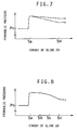
- the hydraulic pressure may be lowered as indicated in the graphs of Figs. 6-8.
- the pattern of changing the flow rate of the flow control valve 68 is predetermined by experiments, for example, so as to establish a desired pattern of lowering the pressure in the hydraulic cylinders 30 and reducing the blank holding pressure, in relation to the vertical positions of the press slide 20 as detected by the position sensors 70. It is noted that the actual pressure in the hydraulic cylinders 30 may be used to re-adjust or feedback-control the flow rate of the flow control valve 68 for intricate control of the blank-holding force exactly following the desired pattern. The necessity of the adjustment of the blank-holding force during a pressing action on the blank 40 depends upon the specific pressing operation or condition on the press.
- the initial hydraulic pressure P should be adjusted to the original optimum level Po.
- the flow control valve 68 serves as flow regulating means for controlling a discharge flow of the fluid from the hydraulic cylinders 30, and the controller 56 serves as means for controlling the flow regulating means.
- the pump 58 and the hydraulic control circuit 54 serve as a pressure source for supplying a pressurized fluid to the hydraulic cylinders 30, while the controller 56, discharge passage 66, shut-off valve 76 and flow control valve 78 constitute a control portion of the cushioning apparatus 44.
- the cushioning apparatus 44 is capable of controlling or changing the blank-holding force by discharging the fluid from the hydraulic cylinders 30 while a pressing action is performed on the blank 40.
- the discharge flow of the fluid from the hydraulic cylinders 30 may be controlled so as to damp the vibration or oscillation of the blank-holding force upon collision of the upper die 18 with the pressure ring 28, whereby an excessive amount of initial movement of the blank 40 relative to the pressure ring 28 and upper die 18 upon such collision is effectively avoided, with a result of improving the surface quality of the article produced from the blank.
- the reduction of the blank-holding force during the pressing action is effective to prevent rupturing of the blank being drawn, and permits the use of a less expensive low-grade material for the blank while assuring a desired quality of the product manufactured from the blank.
- the cushioning apparatus not only assures even distribution of the blank-holding force on the pressure ring 28, but also provides various other advantages for enhanced results of the pressing operation on the press.
- the present cushioning apparatus 44 is adapted to adjust the blank-holding force during a pressing action by partially discharging the pressurized fluid from the balancing hydraulic cylinders 30 whose primary function is to establish even distribution of the blank-holding force. Accordingly, the apparatus 44 does not require a cushioning hydraulic cylinder conventionally used in combination with a cushioning pneumatic cylinder to provide force generating means corresponding to the means 42 of the present embodiment.
- the conventionally used cushioning hydraulic cylinder is connected to a pressure relief valve to control the blank-holding force. In the absence of such cushioning hydraulic cylinder and the pressure relief valve connected to that cushioning hydraulic cylinder, the present cushioning apparatus 44 is comparatively simple and available at a reduced cost.
- the cushioning apparatus 44 may be easily provided on an existing press, by simply connecting the discharge line 66 to the fluid chambers of the balancing hydraulic cylinders 30, and providing the flow control valve 68 in the discharge line 66 so that the flow rate of the flow control valve 68 is controlled by the controller 56 in relation to the vertical position of the press slide 20.
- the apparatus 44 is available on the existing press without considerable modifications of the press.
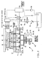
- a solenoid-operated shut-off valve 76 and a manually controlled flow control valve 78 are connected in series in the discharge line 66.
- the flow rate of the flow control valve 78 is manually adjusted to a desired value.
- the shut-off valve 76 is selectively placed in the open and closed positions under the control of the controller 56. For instance, the shut-off valve 76 is opened at a predetermined point Sb in the effective drawing stroke of the slide 20, as indicated in Fig.
- the flow rate of the flow control valve 78 and the moment (Sb) at which the shut-off valve 76 is opened are determined as needed depending upon the specific pressing operation on the press.
- the solenoid-operated shut-off valve 76 and the manually controlled flow control valve 78 serve as the flow regulating means.
- shut-off valves 82a, 82b, 82c and three manually controlled flow control valves 84a, 84b, 84c are provided downstream of the solenoid-operated shut-off valve 76, in place of the manually controlled flow control valve 78 used in the embodiment of Fig. 2.
- the three shut-off valves 82a, 82b, 82c are connected in parallel with each other, and the three flow control valves 84a, 84b, 84c are connected to the respective shut-off valves 82a, 82b, 82c.
- the flow rates of the flow control valves 84a, 84b, 84c are manually adjusted to predetermined different values, and the shut-off valves 82a, 82b, 82c are manually opened and closed by the operator of the press, depending upon the specific pressing operation on the press. Therefore, the overall rate of discharge flow of the fluid from the hydraulic cylinders 30 can be changed in steps by changing the combination of the opened and closed shut-off valves 82a, 82b, 82c. Accordingly, the rate of decrease in the blank-holding force can be changed in steps.
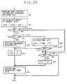
- FIG. 7 illustrate two examples of the hydraulic pressure reduction pattern, in which the solenoid-operated shut-off valve 76 is opened at the point of time Sa, with the respective different combinations of the opened and closed shut-off valves 82a, 82b, 82c.
- the solenoid-operated shut-off valve 76, manually operated shut-off valves 82a, 82b, 82c and manually controlled flow control valves 84a, 84b, 84c constitute the flow regulating means.
- solenoid-operated shut-off valves 88a, 88b, 88c opened and closed by the controller 56 are used in place of the manually operated shut-off valves 82a, 82b, 82c used in the embodiment of Fig. 3.
- the rate of decrease in the blank-holding force can be changed in steps depending upon the selected combination of the opened and closed shut-off valves 88a, 88b, 88c. Further, the rate of decrease in the blank-holding force can be changed even in the process of a pressing action on the blank 40, as indicated in Fig.
- shut-off valves 88a, 88b, 88c can be automatically opened and closed by the controller 56 during the pressing action.
- the solenoid-operated shut-off valves 76, 88a, 88b, 88c and the manually controlled flow control valves 84a, 84b, 84c constitute the flow regulating means.
- a cushioning apparatus 90 uses discharge lines 92 which are connected to the fluid chambers of the hydraulic cylinders 30, but are not directly connected to the manifold 46 which is connected to the hydraulic control circuit 54.
- the discharge lines 92 are provided with flow control valves 94 disposed near the respective hydraulic cylinders 30, so that the fluid may be discharged from the hydraulic cylinders 30 through the flow control valves 94 and the discharge lines 92.
- the discharge lines 92 are connected to the oil reservoir 60 through a flexible tube 96.
- the flow control valves 94 are comparatively compact variable flow control valves, which are controlled by a common control signal received from the controller 56, so as to be selectively placed in a closed position for inhibiting a discharge flow of the fluid from the hydraulic cylinders 30, and an open position for permitting the discharge flow of the fluid at a controlled flow rate, as in the first embodiment of Fig. 1.
- the present apparatus 90 Since the rate of discharge flow of the fluid from each hydraulic cylinder 30 is controlled by the corresponding flow control valve 94 provided in the exclusive discharge lines 92, the present apparatus 90 permits uniform reduction of the pressure values in the individual hydraulic cylinders 30, with less variation in the pattern of the pressure reduction, as compared with the apparatus 44 in which the single flow control valve 68 is provided in the discharge line 66 connected to the fluid supply passage 50. Thus, the present apparatus 90 assures more accurate control of the blank-holding force during a pressing action while maintaining uniform distribution of the blank-holding force on the pressure ring 28. Further, the present apparatus 90 allows relatively rapid discharge of the fluid from the cylinders 30, which results in an increased range of control of the hydraulic pressure, and an accordingly increased range of control of the blank-holding force.
- the cushioning apparatus 90 may be modified so that the individual flow control valves 94 are controlled independently of each other by the controller 56, in terms of their flow rates and/or the point of time at which the valves 94 are opened.
- a cushioning apparatus 100 has the balancing hydraulic cylinders 30 disposed on the cushion platen 26, and the cushion pins 22 associated with the pistons of the hydraulic cylinders 30, as in the embodiment of Fig. 1.
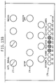
- the cushion platen 26 has four rectangular sections indicated at A, B, C and D in Fig. 10, and the hydraulic cylinders 30 are classified into corresponding four groups.
- four groups of hydraulic cylinders 30a, 30b, 30c and 30d are disposed in the respective rear-right, front-right, rear-left and front-left sections A, B, C and D (upper-right, lower-right, upper-left and lower-left sections A, B, C and D as seen in Fig. 10) of the cushion platen 26.
- this arrangement is capable of adjusting the local blank-holding force values acting on different portions of the pressure ring 28, depending upon the specific configuration and specifications of the blank 40 and varying degrees of wear of the die set which includes the upper die 18, lower die 10 and pressure ring 28.
- the four groups of hydraulic cylinders 30a-30d are connected to respective four supply lines 102a-102d, which are independent of each other.
- the supply lines 102a-102d are connected to respective hydraulic control circuits 104a-104d through respective flexible tubes 108a-108d and respective solenoid-operated shut-off valves 106a-106d.
- the solenoid-operated shut-off valves 106a-106d are controlled by control signals received from the controller 56 (as used in the preceding embodiments), independently of each other, so that the cylinders 30a-30d of the four groups have respective optimum initial hydraulic pressure values Poa-Pod prior to a pressing operation on the blank 40.
- respective four hydraulic pressure sensors 110a-110d for detecting the hydraulic pressure in the supply lines 102a-102d
- respective four discharge lines 112a-112d for partially discharging the fluid from the respective four groups of hydraulic cylinders 30a-30d.
- respective four flow regulating means 114a-114d each of which may consist of the flow control valve 68 used in the embodiment of Fig. 1, for example.
- the flow regulating means 114a-114d are connected to the reservoir 60 through a drain passage 116 and a flexible tube 118.
- Each of the flow regulating means 114 has a closed position for inhibiting the fluid flow therethrough, and an open position for permitting the fluid flow therethrough.
- the four flow regulating means 114a-114d are controlled by control signals received from the controller 56, independently of each other, so as to be selectively placed in the closed and open positions.
- the flow rates of the flow regulating means 114a-114d when placed in the open position may be controlled by the controller independently of each other, when needed.
- the pressure values in the hydraulic cylinders 30a-30d of the four groups can be lowered during a pressing action, independently of each other, depending upon the rates of discharge flows of the fluid through the respective flow regulating means 114a-114d.
- the controller 56 stores data indicative of the optimum initial hydraulic pressure values Poa-Pod indicated above, data indicative of the points of time at which the flow regulating means 114a-114d are opened, and if necessary data indicative of the flow rates of the individual flow regulating means 114a-114d.
- the pressurizing fluid is supplied to the four groups of hydraulic cylinders 30a-30d disposed in the respective four sections A-D of the cushion platen 26, through the respective supply lines 102a-102d, and the initial pressure values in the hydraulic cylinders 30a-30d of the four groups are adjusted to the respective optimum values Poa-Pod by the respective hydraulic control circuits 104a-104d. Further, the fluid can be discharged from each of the four groups of hydraulic cylinders 30a-30d, through the corresponding discharge line 112a, 112b, 112c, 112d, at a given flow rate determined on the corresponding flow regulating means 112a, 112b, 112c, 112d.
- This arrangement permits intricate adjustment of the local blank-holding force values acting on the local portions of the pressure ring 28, which correspond to the four groups of hydraulic cylinders 30a-30d disposed in the respective four sections A, B, C and D of the cushion platen 26.
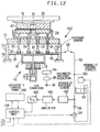
- the single hydraulic control circuit 54 is used in place of the four hydraulic control circuits 104a-104d of Fig. 10 which correspond to the four sections A, B, C and D of the cushion platen 26. More particularly, four mutually independent supply lines 132a-132d connected to the four groups of hydraulic cylinders 30a-30d are connected to the single hydraulic control circuit 54, through the respective flexible tubes 108a-108d and solenoid-operated shut-off valves 106a-106d, and through a common fluid passage 134. The pressure values in the four groups of hydraulic cylinders 30a-30d and the four supply lines 132a-132d are controlled by the respective shut-off valves 106a-106d and the single hydraulic control circuit 54.
- the four supply lines 132a-132d are connected to the respective discharge lines 112a-112d and flow regulating means 114a-114d, so that the discharge flows of the fluid from the cylinders 30a-30d of the four groups are controlled by the flow regulating means 114a-114d independently of each other.
- the cushioning apparatus 130 of Fig. 11 has the same function and advantage as the cushioning apparatus 100 of Fig. 10.
- the fluid passage 50 is connected through a check valve 156 to the pump 58, which is controlled by a control unit 158.
- the fluid passage 50 is also connected to a hydraulic control circuit 160 having a pressure relief valve controlled by the control unit 150 to regulate the pressure P of the fluid delivered from the pump 58.
- the hydraulic control circuit 160 operates to control the initial hydraulic pressure in the hydraulic cylinders 30 to the predetermined optimum value Po prior to a pressing operation.
- the control unit 158 is adapted to receive an output signal of a hydraulic pressure sensor 162 through an amplifier 164 and an A/D converter 166. The output signal of the sensor 162 is indicative of the hydraulic pressure P in the fluid passage 50 and hydraulic cylinders 30.
- the control unit 158 consists principally of a microcomputer incorporating a central processing unit, a random-access memory and a read-only memory.
- the control unit 158 operates according to various control programs stored in the read-only memory, for controlling the pump 58 and the hydraulic control circuit 160, determining the optimum initial hydraulic pressure Po and an optimum in-process hydraulic pressure PXo, and monitoring an in-process hydraulic pressure PX, as explained below.
- the in-process hydraulic pressure PX is the pressure in the hydraulic cylinders 30 during a pressing action on the blank 40
- the optimum in-process hydraulic pressure PXo is the pressure PX which corresponds to the optimum initial hydraulic pressure Po prior to the pressing action.
- To the control unit 158 there is connected an operator's control panel 168 as illustrated in Figs.
- the control unit 158 receives a TEST RUN signal SS generated when a TEST RUN pushbutton provided on the press is activated, and a signal SD generated when the press slide 20 has reached the lower stroke end or a point slightly above the lower stroke end.
- the operator's control panel 168 has various indicators and switches as shown in Figs. 13A and 13B, such as an indicator 170 (Fig. 13A) for indicating the hydraulic pressure P in the hydraulic cylinders 30.
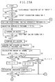
- the optimum initial and in-process hydraulic pressure values Po and PXo are determined according to a routine as illustrated in the flow chart of Figs. 14A and 14B.
- the control unit 158 stores data indicative of a total of ten provisional initial pressure values P1 through P10, where P1 and P10 represent 200kgf/cm 2 and 20kgf/cm 2 , respectively. These provisional initial pressure values P1-P10 decrease in increments of 20kgf/cm 2 , and are selectively and sequentially set the initial hydraulic pressure P, from the highest pressure P1 (200kgf/cm 2 ) to the lowest pressure P10 (20kgf/cm 2 ). It is noted that 1kgf/cm 2 is approximately 9.8 x 10 4 Pa (Pascal).
- Step S3 is followed by step S4 in which the initial hydraulic pressure P prior to a pressing action on the blank 40 is adjusted to the currently selected provisional initial value Pn (set in step S3), for example, P10 (200kgf/cm 2 ) in the first cycle of execution of the routine of Figs. 14A and 14B. That is, the pump 58 and the hydraulic control circuit 160 are operated so that the pressure P is adjusted to a level substantially equal to the provisional initial value Pn, on the basis of the signal from the hydraulic pressure sensor 162.
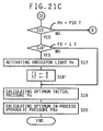
- step S5 is implemented to activate an appropriate buzzer in such fashion that indicates that the pressure P has been adjusted to the currently set provisional value Pn.
- step S6 determines whether the TEST RUN switch on the press has been turned on.
- the TEST RUN signal SS is applied to the control unit 158, which in turn implements step S7 to stop the buzzer, and step S8 in which the press is operated to perform a test pressing operation with one reciprocation of the press slide 20, and a provisional in-process hydraulic pressure PXn in the hydraulic cylinders 30 during a pressing action on the blank 40 is read, stored in the random-access memory, and indicated on the indicator 176.
- the provisional in-process hydraulic pressure PXn corresponds to the provisional initial hydraulic pressure Pn.
- the hydraulic pressure P in the hydraulic cylinders 30 during a pressing cycle vibrates as indicated in Fig. 15.
- the pressure PXn to be read and stored in step s8 is the pressure P when the press slide 20 reaches the lower stroke end indicated at SL in Fig. 15 or a point near this lower stroke end SL, at which the vibration of the pressure P has settled.
- the pressure PXn to be stored in the control unit 158 is the pressure P as detected by the pressure sensor 162 when the signal SD is received by the control unit 158.
- the pressure PXn to be stored may be the maximum, minimum or average value of the pressure values P detected by the time the lower stroke end SL of the slide 20 is reached.
- Step S9 is followed by step S10 to judge whether the amount of change ⁇ PX is equal to or smaller than a predetermined value ⁇ .
- the predetermined value ⁇ is for determining whether the provisional in-process pressure PXn during the pressing action is substantially constant in spite of a change in the provisional initial hydraulic pressure Pn prior to the pressing action. This value ⁇ is determined depending upon the expected fluctuation and detecting error of the pressure value PXn, and is usually set in the neighborhood of 5kgf/cm 2 .
- step S11 is implemented to set a flag F to "1”
- step S12 is implemented to activate one of ten indicator lights 178 (Fig. 13B) on the operator's control panel 168. Described more specifically, the ten indicator lights 178 correspond to the ten provisional initial hydraulic pressure values Pn sequentially set in step S3, and the indicator light 178 corresponding to the preceding value Pn-1 is activated.
- step S10 is followed by step S13 to judge whether the flag F is set at "1". If an affirmative decision (YES) is obtained in step S13, step S14 is implemented to reset the flag F to "0", and step S12 is then implemented as described above.
- the control flow goes to step S15 if a negative decision (NO) is obtained in step S13 or after the step S12 has been implemented.
- step S15 the control unit 158 determines whether the currently set provisional initial value Pn is P10, namely, 20kgf/cm 2 , that is, whether the in-process pressure values PXn corresponding to all the ten provisional initial values P1 through P10 have been detected and stored.
- step S15 If a negative decision (NO) is obtained in step S15, the control flow goes back to step S3. Steps S3 through S15 are repeatedly implemented with the provisional initial values Pn decremented down to 20kgf/cm 2 . In the first cycle of execution of the routine in which the preceding value Pn-1 does not exist, steps S9 through S14 are skipped, and step S8 is followed by step S15.
- the graph of Fig. 16 shows an example of the provisional in-process hydraulic pressure values PXn obtained for the 10 provisional initial hydraulic pressure values Pn, by repeated execution of steps S3-S14.
- the in-process pressure value PX4 corresponding to the initial value P4 140kgf/cm 2
- an affirmative decision is obtained in step S10, whereby the indicator light 178 corresponding to the provisional initial value P4 (140kgf/cm 2 ) is activated.
- the affirmative decision is obtained in step S10 for the provisional initial values P6 (100kgf/cm 2 ) and P7 (80kgf/cm 2 ), and the indicator lights 178 corresponding to the provisional initial value P5 (120kgf/cm 2 ) and P6 (100kgf/cm 2 ) are activated.
- An optimum range of the initial hydraulic pressure Pn indicated by the activated indicator lights 178 corresponds to a range C of Figs. 16 and 17 in which the amount of change ⁇ PX of the in-process hydraulic pressure PXn is smaller than the predetermined value ⁇ in spite of the change in the provisional initial value Pn. While the initial hydraulic pressure values Pn of all the hydraulic cylinder 30 are held within this optimum range, the pistons of the cylinders 30 connected to the corresponding cushion pins 22 are all located between their upper and lower stroke ends, as indicated in Fig. 17, during the pressing action, without bottoming of the pistons even with the press slide 20 lowered down to its lower stroke end. Thus, the range C is the optimum range of the initial hydraulic pressure P.
- the range of the provisional initial hydraulic pressure values Pn and the decrementing amount used in step S3 to detect the optimum range C are suitably determined for specific individual pressing operations which are effected with different blank-holding forces and different numbers of the cushion pins 22.
- the range of the values Pn and the decrementing amount are determined depending upon the number of the hydraulic cylinders 30, pressure-receiving area and travel distance of the pistons of the cylinders 30, and optimum range of the blank-holding force, so that the optimum range C of the initial hydraulic pressure P can be detected for each specific pressing job.
- the optimum initial hydraulic pressure value is estimated according to the equation (1) identified above, depending upon the blank-holding force and the number of the cushion pins 22, and the range of the initial hydraulic pressure values Pn is determined so as to include the thus estimated optimum initial hydraulic pressure value.
- the abnormality can be detected by the operating states of the indicator lights 178. For example, none of the lights 178 are activated, or none of the successive lights 178 are activated.
- the provisional initial hydraulic pressure Pn can be set as desired by using Pn setting dials 180 (Fig. 13A) on the panel 168.
- the in-process hydraulic pressure PX is indicated on the indicator 176, which facilitates the manual setting of the initial hydraulic pressure Pn, namely, sequential changing of the provisional initial value Pn by a desired decremental or incremental amount, to detect a change in the in-process hydraulic pressure PXn and determine the optimum range C of the initial hydraulic pressure P.
- step S16 is for determining whether the flag F is set at "1" or not. If so, the step S17 is implemented to activate the indicator light 178 corresponding to the last provisional initial value P10 (20kgf/cm 2 ). Then, the control flow goes to step S18 to reset the flag F to "0, and to step S19. If the negative decision (NO) is obtained in step S16, the control flow goes directly to step S19, skipping steps S17 and S18.
- Steps S16 through S18 are provided to activate the indicator light 178 corresponding to the last provisional initial value P10, if the amount of change ⁇ PX of the in-process pressure PX10 corresponding to the last initial value P10 is equal to or smaller than the predetermined value ⁇ .
- Step S19 is provided to calculate an optimum initial hydraulic pressure Po, which is an average of the provisional initial pressure values Pn whose indicator lights 178 are currently activated.
- the calculated optimum initial hydraulic pressure Po is stored in the random-access memory of the control unit 158.
- the control flow goes to step S20 to calculate an optimum in-process hydraulic pressure PXo, which is an average of the stored provisional in-process pressure values PXn corresponding to the indicator lights 178 which are currently activated.
- the calculated optimum in-process hydraulic pressure PXO is stored in the random-access memory of the control unit 158, together with the optimum initial hydraulic pressure Po. These values Po and PXo are used as information indicative of the optimum operating condition of the hydraulic cylinders 30.
- the routine of Figs. 14A and 14B is performed to obtain the optimum initial and in-process hydraulic pressure values Po and PXo.
- the pump 58 and the hydraulic control circuit 160 are operated to adjust the initial hydraulic pressure P to the stored optimum initial value Po, as indicated in Fig. 18, prior to a drawing operation, when the slide 20 is in its upper stroke end, for example.
- the optimum initial hydraulic pressure Po permits the pistons of all the hydraulic cylinders 30 to be held between their upper and lower stroke ends during a drawing action on the blank 40, whereby the blank-holding force is substantially evenly distributed on the pressure member 28, so that the blank 40 is held under a substantially uniform surface pressure over its entire surface area contacting the pressure member 28.
- the in-process hydraulic pressure PX during the drawing operation is read and compared with the stored optimum in-process value PXo, as indicated in Fig. 19. If the actual in-process pressure PX is not substantially equal to the optimum value PXo, an alarm light 182 on the operator's control panel 168 is turned on, or a buzzer is activated in a suitable fashion to inform the operator of the press of some abnormality of the press. It is possible to adjust the initial hydraulic pressure P so that the in-process hydraulic pressure PX substantially coincides with the optimum value PXo.
- the blank-holding force Fs may be obtained according to the equation (2) indicated above, on the basis of the pressure-receiving area As of the hydraulic cylinders 30, weight Wp of the cushion pins 22 and weight Wr of the pressure ring 28, as well as the optimum in-process pressure value PXo.
- the in-process hydraulic pressure values PXn corresponding to the predetermined ten provisional initial hydraulic pressure values Pn are detected to determine the optimum range C of the initial values Pn in which the amount of change ⁇ PX of the in-process pressure value PX due to a change in the initial value P does not exceed the predetermined value ⁇ .
- the optimum initial hydraulic pressure Po is obtained by calculating the average of the provisional initial hydraulic pressure values Pn within the determined optimum range C
- the optimum in-process hydraulic pressure PXo is obtained by calculating the average of the in-process pressure values PXn corresponding to the initial values Pn within the optimum range C.
- the above arrangement permits simpler and more accurate determination of the optimum initial and in-process hydraulic pressure values Po and PXo, than the conventional arrangement in which the optimum values are obtained according to the above equations (1) and (2), on the basis of the average stroke Xav and pressure-receiving area As of the pistons of the hydraulic cylinders 30, volume modulus of elasticity K of the working fluid, total volume V of the fluid, etc.
- the present embodiment assures reduced defects of the products due to uneven distribution of the blank-holding force on the pressure member 28.
- the on-off states of the indicator lights 178 enable the operator to find some abnormality of the cushioning apparatus 150.
- the operator's control panel 168 and the switches on the press permit automatic detection of the in-process hydraulic pressure values PXn, automatic calculation of the amount of change ⁇ PX, automatic determination of the optimum range C of the initial hydraulic pressure P, and automatic determination or calculation of the optimum initial and in-process pressure values Po and PXo based on the determined optimum range C. Accordingly, the operator's working load is reduced, and inadequate setting of the operating condition of the press due to erroneous operation by the operator can be effectively avoided.
- steps S3, S4 and S8 implemented by the control unit 158 constitute a step of obtaining the relationship between the initial and in-process hydraulic pressure values Pn and PXn as illustrated in the graph of Fig. 16, while steps S9, S10, S12 and S17 constitute a step of determining the optimum range C of the initial hydraulic pressure value Pn in which the in-process hydraulic pressure value PXn is substantially constant irrespective of the change in the initial value Pn, or the amount of change ⁇ PX is not larger than the predetermined value ⁇ .
- the pressure sensor 162 serves as means for detecting the hydraulic pressure P in the hydraulic cylinders 30, while the portion of the control unit 158 assigned to implement steps S3 and S4 cooperates with the pump 58 and hydraulic control circuit 160 to constitute initial pressure changing means for changing the provisional initial hydraulic pressure value Pn in a plurality of steps at a predetermined rate of change, that is, in decrements of 20kgf/cm 2 . It is also noted that the portion of the control unit 158 assigned to implement steps S8 and S9 constitutes calculating means for calculating the amount of change ⁇ PX in the in-process hydraulic pressure PX.
- the portion of the control unit 158 assigned to implement step S10 constitutes judging means for judging whether the amount of change ⁇ PX is larger than the predetermined value ⁇ , while the portion of the control unit 158 assigned to implement steps S12, S17, S19 and S20 constitutes means for determining the optimum initial and in-process hydraulic pressure values Po and PXo, that is, the optimum operating condition of the hydraulic cylinders 30, on the basis of the provisional initial hydraulic pressures Pn within the optimum range C.
- the in-process value PXn does not substantially change with the initial value Pn due to air trapped in the working fluid, when the initial value Pn is relatively low.
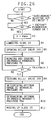
- a routine to determine the optimum initial and in-process hydraulic pressure values Po and PXo which routine is adapted to avoid erroneous determination of the optimum range of the initial value Pn for the reason explained above.
- the same reference numerals as used in the preceding embodiments will be used to identify the functionally corresponding elements.
- steps S1 through S8 of the routine are similar to those of the routine of Fig. 14A.
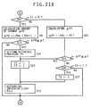
- step S8 is followed by step S21 (Fig. 21B) to determine whether a flag F1 is set at "0". Since the flag F1 is reset to "0" in the initialization process of the control unit 158, step S21 is followed by step S9 in the first cycle of execution of the routine.
- Step S10 is then implemented to judge whether the amount of change ⁇ PX calculated in the preceding step S9 is equal to or smaller than the predetermined value ⁇ .
- step S10 If the affirmative decision (YES) is obtained in step S10, the control flow goes to step S22 to set a reference hydraulic pressure value PY, and to step S23 to set the flag F1 and a flag F2 to "1".
- the reference value PY is subsequently used as a basis on which the amount of change in the in-process value PXn is calculated.
- the reference value PY may be the in-process value PXn obtained in step S8 in the present cycle of execution of the routine, or the in-process value PXn-1 obtained in step S8 in the last cycle of execution of the routine, or may alternatively be the average value of the values PXn and PXn-1.
- Step S23 is followed by step S12 wherein the indicator light 178 on the panel 168 which corresponds to the preceding initial value Pn-1 is activated.
- step S21 is followed by step S24 in the next cycle of execution of the routine.
- step S24 is followed by step S25 to judge whether the amount of change ⁇ PY is equal to or smaller than the predetermined value ⁇ or not.
- the value ⁇ used in step S25 may be different from that used in step S10.
- step S25 If an affirmative decision (YES) is obtained in step S25, steps S23 and S12 are implemented to activate the indicator light 178 corresponding to the preceding initial hydraulic pressure value Pn-1. If the amount of change ⁇ PY is larger than the predetermined value ⁇ or if a negative decision (NO) is obtained in step S25, the control flow goes to step S26 to determine whether the flag F2 is set at "1". If the flag F2 is set at "1", step S27 is implemented to reset the flag F2 to "0”, and the control flow goes to step S15 (Fig. 21C) through step S12. If the flag F2 is set at "0", the control flow goes directly to step S15. Step S15 is followed by step S16' to determine whether the flag F2 is set at "1".
- step S17 is followed by step S18' to reset the flags F1 and F2 to "0".
- step S22 is provided to set the reference hydraulic pressure value PY, when the affirmative decision (YES) is obtained in step S10 for the first time (that is, when the amount of change ⁇ PX has become equal to or smaller than the predetermined value ⁇ for the first time).
- the reference pressure value PY is determined by the in-process pressure value PXn detected when the affirmative decision (YES) is obtained in step S10 for the first time.
- the value PY may be the present in-process pressure value PXn, the preceding in-process pressure value PXn-1 or the average of the values PXn and PXn-1.
- this value PY is used in the subsequent cycles of execution of the routine, to judge whether the amount of change of the in-process value PXn with a change in the initial value Pn is substantially constant. Namely, the present in-process value PXn is compared with the reference value PY to obtain the amount of change ⁇ PY in step S24, and the thus obtained amount of change ⁇ PY is compared with the predetermined value ⁇ in step S25.
- the in-process hydraulic pressure value PX4 or PX5 or the average of these values PX4 and PX5 is used as the reference value PY.
- the optimum initial hydraulic pressure Po is calculated in step S19 on the basis of the provisional initial pressure values P4 through P7 within the optimum range C, and not on the basis of the provisional initial pressure values P9 and P10 which are almost equal to each other.
- the amount of change ⁇ PY corresponding to the initial value P9 is necessarily larger than the predetermined value ⁇ since the difference of the in-process value PX9 with respect to the reference value PY is considerably large.
- the present arrangement is capable of avoiding an erroneous determination of the optimum range of the initial pressure on the basis of the initial values P9 and P10, and assures correct determination of the optimum range C on the basis of the initial values P4-P7, and accurate calculation of the optimum initial and in-process pressure values Po and PXo on the basis of the values Pn within the determined optimum range C and the corresponding in-process values PXn.
- steps S3, S4 and S8 constitute a step of obtaining the relationship between the initial and in-process hydraulic pressure values Pn and PXn
- steps S9, S10, S12, S17, S22, S24 and S25 constitute a step of determining the optimum range C of the initial hydraulic pressure value Pn.
- the pressure sensor 162 serves as means for detecting the hydraulic pressure P
- the portion of the control unit 158 assigned to implement steps S3 and S4 cooperates with the pump 58 and hydraulic control circuit 160 to constitute initial pressure changing means for changing the provisional initial hydraulic pressure value Pn.
- the portion of the control unit 158 assigned to implement steps S8, S9, S22 and S24 constitutes calculating means for calculating the amount of change ⁇ PX, ⁇ PY.
- the portion of the control unit 158 assigned to implement step S10 and S25 constitutes judging means for judging whether the amount of change ⁇ PX, ⁇ PY is larger than the predetermined value ⁇ , while the portion of the control unit 158 assigned to implement steps S12, S17, S19 and S20 constitutes means for determining the optimum initial and in-process hydraulic pressure values Po and PXo, that is, the optimum operating condition of the hydraulic cylinders 30. It is also noted that the portion of the control unit 158 assigned to implement steps S21 and S23 provides means for inhibiting steps S9 and S10 from being implemented once the affirmative decision (YES) is obtained in step S10.
- FIG. 22 One modification of the preceding embodiment of Figs. 21A, 21B and 21C is illustrated in the flow chart of Fig. 22.
- This modified embodiment also includes steps S21 through S27 as in the preceding embodiment. While step S21 is implemented between steps S8 and S9 in the preceding embodiment, this step S21, if implemented, follows step S10 in the present modified embodiment of Fig. 22. More specifically, steps S8, S9 and S10 are successively implemented in the order of description as in the embodiment of Figs. 14A and 14B, so that the amount of change ⁇ PX calculated in step S9 based on the in-process hydraulic pressure value PXn read and stored in step S8 is compared with the predetermined value ⁇ in step S10.
- step S10 is followed by step S21 to determine whether the flag F1 is set at "0". Since the flag F1 has been initialized to "0", the affirmative decision (YES) is obtained in step S21 when this step S21 is implemented for the first time. As a result, step S21 is followed by step S22 in which the reference hydraulic pressure value PY is set as described above with respect to the preceding embodiment of Figs. 21A, 21B and 21C. Then, the control flow goes to step S23 to set the flags F1 and F2 to "1", and step S12 to turn on the indicator light 178 corresponding to the preceding provisional initial hydraulic pressure value Pn-1.
- step S10 Once the affirmative decision (YES) has been obtained in step S10 and the flag F1 has been set to "1" in step S23, the negative decision (NO) is obtained in step S21 in the next cycle of execution of the routine, whereby step S21 is followed by step S24. If the negative decision (NO) is obtained in step S10, namely, if the amount-of change ⁇ PX is larger than the predetermined value ⁇ , step S10 is followed by step S26.
- step S21 and the subsequent steps are implemented only after the amount of change ⁇ PX has become equal to or smaller than the predetermined value ⁇ .
- step S21 is followed by step S24 and the subsequent steps, so that the in-process hydraulic pressure value PXn is compared with the reference value PY.
- the affirmative decision (YES) in step S10 will not result in automatic implementation of step S12.
- step S12 will not be implemented again unless the affirmative decision (YES) is obtained in step S25 (unless the amount of change ⁇ PY has become equal to or smaller than the predetermined value ⁇ ) after the affirmative decision (YES) is obtained in step S10 (the amount of change ⁇ PX has become equal to or smaller than the value ⁇ ).
- the negative decision (NO) is obtained in step S25, the flag F2 is set to "0" in step S27, and the negative decision (NO) is obtained in step S26 in the next cycle, whereby step S12 will not be implemented.
- the embodiment of Fig. 22 has the same advantage as the preceding embodiment of Figs. 21A, 21B and 21C.
- FIG. 23A and 23B A modification of the embodiment of Figs. 14A and 14B is illustrated in the flow chart of Figs. 23A and 23B in which steps S1 through S10 are implemented as in the embodiment of Figs. 14A and 14B.
- the present modified embodiment uses two flags F1 and F2. If the affirmative decision (YES) is obtained in step S10, step S28 is implemented to set the flag F1 to "1", and then step S12 is implemented to activate the indicator light 178 corresponding to the preceding provisional initial hydraulic pressure value Pn-1. If the negative decision (NO) is obtained in step S10, step S29 is implemented to determine whether the flag F1 is set at "1".
- step S29 is followed by step S30 in which the flag F1 is reset to "0" while the flag F2 is set to "1".
- step S12 is followed by step S31 to determine whether the flag F2 is set at "1". If this flag F2 is set at "0", the control flow goes to step S15 (Fig. 23B) and the subsequent steps. If the flag F2 is set at "1", that is, if the negative decision (NO) is obtained in step S10 and steps S29 and 30 are implemented after the affirmative decision (YES) is once obtained in step S10, the control flow goes directly to step S18'' and the subsequent steps (Fig. 23B), and the routine is terminated.
- steps S16'', S17 and S18'' are implemented if the affirmative decision (YES) is obtained in step S10 when the last provisional initial hydraulic pressure value P10 (20kgf/cm 2 ) is established, or if the affirmative decision (YES) is not obtained (step S12 is not implemented) for any one of the ten provisional initial hydraulic pressure values Pn.
- Step S16'' is implemented to determine whether the flag F1 is set at "1". If the flag F1 is set at "1", step S16 is implemented to activate the indicator light 178 corresponding to the current provisional initial hydraulic pressure value Pn, namely, P10 (20kgf/cm 2 ).
- Step S17 is followed by step S18'' to reset the flags F1 and F2 to "0".
- step S30 if the negative decision (NO) is obtained in step S10 after the affirmative decision (YES) is once obtained in step S10. In this case, therefore, the control flow does not return to step S3 through step S15, but goes to step S18'', whereby the routine is terminated once the negative decision (NO) following the affirmative decision (YES) is obtained in step S10. Accordingly, step S12 will not be implemented successively with the relatively low provisional initial hydraulic pressure values Pn once this step S12 has been implemented with the relatively high provisional initial hydraulic pressure values Pn.
- steps S3, S4 and S8 constitute a step of obtaining the relationship between the initial and in-process hydraulic pressure values Pn and PXn
- steps S9, S10, S12 and S17 constitute a step of determining the optimum range C of the initial hydraulic pressure value Pn, as in the embodiment of Figs. 14A and 14B.
- the present embodiment is also similar to the embodiment of Figs.
- the portion of the control unit 158 assigned to implement steps S3 and S4 cooperates with the pump 58 and hydraulic control circuit 160 to constitute initial pressure changing means for changing the provisional initial hydraulic pressure value Pn
- the portion of the control unit 158 assigned to implement steps S8 and S9 constitutes calculating means for calculating the amount of change ⁇ PX.
- the portion of the control unit 158 assigned to implement step S10 constitute judging means for judging whether the amount of change ⁇ PX is larger than the predetermined value ⁇
- the portion of the control unit 158 assigned to implement steps S12, S17, S19 and S20 constitutes means for determining the optimum initial and in-process hydraulic pressure values Po and PXo.
- control unit 158 assigned to implement steps S30 and S31 provides means for inhibiting steps S3-S10 (in particular step S10) after the negative decision (NO) following the affirmative decision (YES) is obtained in step S10 for the first time.
- step S31 to determine whether the flag F2 is set at "1" is implemented between steps S8 and S9. If the flag F2 is set at "1", step S9 and subsequent steps including step S12 are not implemented, and the control flow returns to step S3 through step S15, for implementing step S8 for the remaining provisional initial hydraulic pressure values Pn.
- the in-process pressure values PXn are detected, stored, and displayed on the operator's control panel 168 even after the negative decision (NO) following the affirmative decision (YES) is obtained in step S10.
- the present embodiment is capable of obtaining the relationship between the provisional initial and in-process pressure values Pn and PXn over the entire range of the initial value Pn.
- the present embodiment is similar to the preceding embodiment of Figs. 23A and 23B, regarding the activation of the indicator lights 178 in step S12, and the calculation of the optimum initial and in-process hydraulic pressure values Po and PXo.
- Figs. 14, 21, 22, 23 and 24 are adapted to determine the optimum initial and in-process hydraulic pressures Po and PXo, by detecting the in-process pressure values PXn during different test pressing cycles effected with different provisional initial hydraulic pressure values Pn.
- the optimum in-process pressure PXo may be determined by detecting the in-process pressure value PXn while changing the amount of fluid in the hydraulic cylinders 30 when the upper die 18 is held in abutting contact with the pressure ring 28.
- a cushioning apparatus 188 illustrated in Fig. 25 incorporates one example of such a device adapted to determine the optimum in-process hydraulic pressure PXo on the basis of the detected in-process pressure PX which varies with a change in the amount of the fluid in the cylinders 30.
- the fluid passage 50 is connected to a constant-flow discharge valve 190 as well as to the hydraulic control circuit 160.
- the discharge valve 190 is opened and closed according to a signal received from the control unit 158, during execution of a routine as illustrated in the flow chart of Fig. 26.
- the discharge valve 190 placed in its open position permits the fluid to flow therethrough at a predetermined rate.
- the present apparatus 188 does not require the indicator lights 178 on the operator's control panel 168.
- the routine is started with steps R1 and R2 to determine whether the AUTO-MANUAL selector 172 is set at "AUTO" while the SETUP pushbutton 174 is on. If an affirmative decision (YES) is obtained in both of these steps R1 and R2, the control flow goes to step R3 in which the pump 58 and the hydraulic control circuit 160 are activated and controlled to regulate the hydraulic pressure P in the fluid passage 50 and hydraulic cylinders 30 prior to a pressing operation, so that the pressure P as detected by the hydraulic pressure sensor 162 is adjusted to a predetermined maximum level Pmax, which may be 200kgf/cm 2 , for example.
- a predetermined maximum level Pmax which may be 200kgf/cm 2 , for example.
- step R4 is implemented to lower the press slide 20 to a predetermined blank-holding position in which the upper die 18 attached to the press slide 20 is forced against the pressure ring 28.
- the blank-holding position may be the lower stroke end of the slide 20 which is detected by the signal SD indicative of the lower stroke end of the slide 20.
- step R5 is implemented to open the constant-flow discharge valve 190 so that the fluid is discharged from the hydraulic cylinders 30 and passage 50 at a given flow rate, into the reservoir 60.
- the hydraulic pressure PX which decreases as the fluid is discharged, is detected and stored in the random-access memory of the control unit 158 in step R6.
- Step R6 is repeatedly implemented at a predetermined time interval until an affirmative decision (YES) is obtained in step R7, namely, until the detected hydraulic pressure PX is lowered down to a predetermined lower limit PXmin, which may be approx. 150kgf/cm 2 , for instance.
- a predetermined lower limit PXmin which may be approx. 150kgf/cm 2 , for instance.
- the control flow goes to step R8 to close the discharge valve 190, and step R9 to determine an optimum range of the hydraulic pressure PX on the basis of the pressure values PX detected in step R6.
- the hydraulic pressure values Pmax and PXmin may be predetermined constant values, or selected as desired with appropriate switches by the operator.
- those values Pmax and PXmin may be determined on the basis of estimated initial and in-process pressure values which are calculated according to the above equation (1) or (2) and depending upon the other operating conditions of the press such as the desired blank-holding force and the number of the cushion pins 22 used.
- the hydraulic pressure PX detected in step R6 varies with time as indicated in the graph of Fig. 27 as the fluid is discharged from the hydraulic circuit including the hydraulic cylinders 30.
- Changing the amount of the fluid in the hydraulic circuit by discharging the fluid through the relief valve 160 provides substantially the same result in connection with the hydraulic pressure PX, as the changing of the initial hydraulic pressure P in the preceding embodiments of Figs. 14 and 21-24. That is, when the pistons of the hydraulic cylinders 30 are located at their neutral positions permitting even distribution of the blank-holding force, the pressure PX in the hydraulic circuit is kept substantially constant, in spite of the change in the amount of the fluid in the hydraulic circuit, which causes only slight movements of the cylinder pistons.
- the pressure values PX successively detected in step R6 are checked in step R9 to see if the amount of change of the successive pressure values PX does not exceed a predetermined value. If the amount of change is not larger than the predetermined value, the appropriate successive pressure values PX can be determined to fall within the optimum range.
- the pressure PX is held in the optimum range during a time period indicated at Ct. This time period Ct corresponds to an optimum range of the fluid amount in the hydraulic circuit.
- the determination in step R9 may be made by comparing an amount of change ⁇ PX and/or an amount of change ⁇ PY with a predetermined value as in the embodiments of Figs. 14 and 21-24. If the optimum range of the fluid amount cannot be determined or two or more optimum ranges are recognized, this means some abnormality of the cushioning apparatus 188, and an alarm light or buzzer is activated to indicate the abnormality.
- step R10 the optimum in-process hydraulic pressure PXo is determined on the basis of the pressure values PX within the optimum range determined in step R9.
- the optimum in-process hydraulic pressure PXo may be an average of the pressure values PX within the optimum range.
- the determined optimum value PXo is stored in the random-access memory of the control unit 158.
- Step R10 is followed by step R11 to move the slide 20 back to its upper stroke end.
- the routine of Fig. 26 is terminated.
- the initial hydraulic pressure P prior to a pressing action is adjusted to an optimum value Po so that the in-process pressure PX is substantially equal to the optimum value PXo determined in step R10.
- the value PXo may be used to monitor the actual in-process pressure PX, as illustrated in the flow chart of Fig. 19.
- This cushioning apparatus 188 also permits easy and accurate determination of the optimum in-process hydraulic pressure PXo, and diagnosis regarding the hydraulic pressure of the cylinders 30, without the conventionally required calculation according to the above equation (1) or (2) on the basis of the average operating stroke Xav and pressure-receiving area As of the pistons of the cylinders 30, the volume modulus of elasticity K and total volume of the fluid, etc. Further, the routine to determine the optimum in-process hydraulic pressure PXo is performed fully automatically in a single test operation in which the hydraulic pressure PX is detected as the fluid is discharged from the hydraulic circuit through the discharge valve 190, with the press slide 20 held in abutting contact with the pressure ring 28.
- the present apparatus 188 assures more efficient determination of the optimum value PXo, than the preceding embodiments in which many test pressing cycles are performed with different provisional initial hydraulic pressure values Pn, each cycle being started by manipulation of the TEST RUN switch provided on the press.
- the portion of the control unit 158 assigned to implement step R4 corresponds to a step of holding the press slide 20 in abutting contact with the pressure ring 28, and the portion of the control unit 158 assigned to implement steps R5 and R6 corresponds to a step of detecting the hydraulic pressure PX while the amount of the fluid in the hydraulic circuit including the cylinders 30 is changed. Further, the portion of the control unit 158 assigned to implement step R9 corresponds to a step of determining an optimum range of the hydraulic pressure PX in which the pressure PX is substantially constant irrespective of a change in the amount of the fluid in the hydraulic circuit.
- the discharge flow of the fluid from the hydraulic cylinders 30 is controlled on the basis of the vertical position of the press slide 20 or upper die 18 as detected by the position sensors 70.
- the hydraulic pressure sensor 62 may be used to control the flow regulating means.
- the hydraulic pressure detected by the sensor 62 may be used to determine the point at which the flow regulating means is commanded to initiate the fluid discharge from the hydraulic cylinders 30.
- the position sensors 70 may be a sensor capable of continuously detecting a linear or angular position, such as a magnetic length measuring device for sensing the position of the press slide 20, or a rotary encoder for detecting the rotating angle of a crank of the drive mechanism for the slide 20.
- the single controller 56 is assigned to control not only the initial hydraulic pressure Po of the hydraulic cylinders 30 but also the discharge flow of the fluid from those cylinders 30.
- the initial hydraulic pressure Po and the discharge flow of the fluid may be controlled by two exclusive controllers.
- the controller 56 may be replaced by four controllers corresponding to the four groups of hydraulic cylinders 30a-30d disposed in the four sections A-D of the platen 26.
- each hydraulic cylinder 30 considered as the smallest independent unit is connected to a supply line and a discharge line such that the individual hydraulic cylinders are independent of each other.
- the initial hydraulic pressure values in the individual cylinders and the discharge flows of the fluid from those cylinders are controlled independently of each other.
- the four hydraulic control circuits 104a-104d control the initial pressures values of the four groups of hydraulic cylinders 30a-30d to the respective different optimum values Poa-Pod depending upon the pneumatic pressure of the single pneumatic cylinder 32, so that the pistons of the hydraulic cylinders 30a-30d of the four groups are all placed in their neutral positions during a pressing action on the blank 40.
- the original blank-holding force values corresponding to the four pneumatic cylinders 32 may be adjusted to respective different optimum values, and the optimum initial hydraulic pressures Poa-Pod may be selected over a comparatively wide range depending upon the established optimum original blank-holding force values.
- the embodiment of Fig. 11 in which the four hydraulic pressure sensors 110a-110d are provided for the respective four groups of hydraulic cylinders 30a-30d is capable of adjusting the initial hydraulic pressures of the four groups of cylinders 30a-30d independently of each other.
- a single hydraulic pressure sensor may be provided in the common fluid passage 134 (between the hydraulic control circuit 54 and the solenoid-operated shut-off valves 106a-106d).
- the initial hydraulic pressure values of the four groups of hydraulic cylinders 30a-30d are adjusted to the same optimum value by the hydraulic control circuit 54, but the discharge flows of the fluid from the four groups of hydraulic cylinders 30a-30d can be controlled by the respective four flow regulating means 114a-114d independently of each other.
- step S5 the buzzer is turned on in step S5 after the hydraulic pressure adjustment to the preset initial pressure value Pn in step S4, to prompt the operator to turn on the TEST RUN switch in step S6.
- steps S5 and S6 are replaced by a step in which a test pressing cycle is automatically initiated aster the hydraulic pressure adjustment in step S4.
- the indicator lights 178 are provided in the embodiments of Figs. 14 and 21-24 to indicate the optimum range of the initial hydraulic pressure Pn, these lights 178 may be eliminated, provided the control unit 158 is adapted to store the provisional initial hydraulic pressure values Pn which correspond to the in-process hydraulic pressure values PXn whose amount of change ⁇ PX is not larger than the predetermined value ⁇ .
- the press or operator's control panel 168 may be equipped with a liquid crystal display or other display means for indicating the obtained relationship between the provisional initial and in-process hydraulic pressure Pn and PXn as illustrated in the graph of Fig. 16.
- the operator of the press may determine the optimum initial pressure Po and/or the optimum in-process pressure PXo.
- Such display means may be employed in the embodiment of Figs. 25-27, to indicate the detected hydraulic pressure PX in relation to time or the amount of the fluid in the hydraulic circuit, as illustrated in the graph of Fig. 27.
- the provisional initial hydraulic pressure values Pn are set in step S4, in the order from the highest value P1 (200kgf/cm 2 ) to the lowest value P10 (20kgf/cm 2 ).
- the pressure Pn may be set starting with the lowest value (20kgf/cm 2 ).
- the highest and lowest values of the provisional initial pressure Pn, and the interval of the values Pn may be manually set by the operator.
- Figs. 25-27 is adapted to discharge the fluid at a constant flow rate through the constant-flow discharge valve 190, it is possible to discharge the fluid through a flow restrictor.
- a cumulative amount of the fluid discharged is detected by a suitable sensor, so that the optimum in-process pressure PXo is determined on the basis of a relationship between the detected cumulative amount of the discharged fluid and the detected pressure PX. It is also possible to intermittently discharge the fluid by a predetermined amount for each discharge, and detect the pressure PX at the end of each discharge.
- the optimum hydraulic pressure PXo may be determined by detecting the pressure PX while the pressure of the pressurized fluid delivered from the pump 58 is raised from a low level by the hydraulic control circuit 160.
- step R11 may be preceded by a step in which the pressure of the fluid delivered from the pump 58 is raised to the optimum in-process pressure value PXo determined in step R10. This step is followed by step R11 to move the press slide 20 to its upper stroke end, and then detect the hydraulic pressure as the optimum initial pressure Po. It is also possible to stop the discharge flow of the fluid when the amount of change in the in-process pressure PX becomes smaller than a predetermined value. In this case, the pressure value PX detected last is determined as the optimum in-process hydraulic pressure PXo, and the pressure detected after the slide 20 is returned to the upper stroke end is determined as the optimum initial hydraulic pressure Po.
- the presses equipped with the illustrated cushioning apparatuses are adapted such that the punch 10 (lower die) is disposed on the base 16 through the press carrier 14, the cushioning apparatus of the present invention is also applicable to a press in which the punch 10 is disposed otherwise, for instance, directly attached to the base 16.
- the force generating means 42 used in the illustrated embodiments uses the pneumatic cylinder 32, a hydraulic cylinder equipped with a pressure relief valve whose relief pressure is variable, or a spring may be used as the force generating means.
Applications Claiming Priority (19)
| Application Number | Priority Date | Filing Date | Title |
|---|---|---|---|
| JP321256/92 | 1992-11-05 | ||
| JP32125592 | 1992-11-05 | ||
| JP321255/92 | 1992-11-05 | ||
| JP32125692 | 1992-11-05 | ||
| JP32125592 | 1992-11-05 | ||
| JP32125692 | 1992-11-05 | ||
| JP32240592 | 1992-11-06 | ||
| JP32240592A JP2848168B2 (ja) | 1992-11-06 | 1992-11-06 | プレス機械の荷重測定装置 |
| JP322405/92 | 1992-11-06 | ||
| JP12529193 | 1993-04-28 | ||
| JP12529193A JP2924562B2 (ja) | 1993-04-28 | 1993-04-28 | プレス機械の荷重設定方法 |
| JP125291/93 | 1993-04-28 | ||
| JP13139793 | 1993-05-07 | ||
| JP13139893 | 1993-05-07 | ||
| JP5131397A JP2753675B2 (ja) | 1992-11-05 | 1993-05-07 | プレス機械のダイクッション装置 |
| JP131398/93 | 1993-05-07 | ||
| JP5131398A JP2711980B2 (ja) | 1992-11-05 | 1993-05-07 | 均圧クッション装置の均圧条件診断方法およびその方法を用いた均圧条件設定装置 |
| JP131397/93 | 1993-05-07 | ||
| EP19930308741 EP0596696B1 (de) | 1992-11-05 | 1993-11-02 | Ziehkissen und Verfahren zur Optimierung dessen Zylinderstiftendrucks |
Related Parent Applications (2)
| Application Number | Title | Priority Date | Filing Date |
|---|---|---|---|
| EP93308741.3 Division | 1993-11-02 | ||
| EP19930308741 Division EP0596696B1 (de) | 1992-11-05 | 1993-11-02 | Ziehkissen und Verfahren zur Optimierung dessen Zylinderstiftendrucks |
Publications (3)
| Publication Number | Publication Date |
|---|---|
| EP0773075A2 true EP0773075A2 (de) | 1997-05-14 |
| EP0773075A3 EP0773075A3 (de) | 1997-10-15 |
| EP0773075B1 EP0773075B1 (de) | 2002-05-29 |
Family
ID=27552670
Family Applications (3)
| Application Number | Title | Priority Date | Filing Date |
|---|---|---|---|
| EP97200413A Expired - Lifetime EP0773075B1 (de) | 1992-11-05 | 1993-11-02 | Verfahren und vorrichtung zur regelung überprüfung oder optimierung des zylinderstiftendrucks einer presse durch flüssigkeits oder anfangsdruckausstoss |
| EP19930308743 Expired - Lifetime EP0596697B1 (de) | 1992-11-05 | 1993-11-02 | Verfahren und Vorrichtung zum Messen und Einstellen der Presskräfte an einer Presse |
| EP19930308741 Expired - Lifetime EP0596696B1 (de) | 1992-11-05 | 1993-11-02 | Ziehkissen und Verfahren zur Optimierung dessen Zylinderstiftendrucks |
Family Applications After (2)
| Application Number | Title | Priority Date | Filing Date |
|---|---|---|---|
| EP19930308743 Expired - Lifetime EP0596697B1 (de) | 1992-11-05 | 1993-11-02 | Verfahren und Vorrichtung zum Messen und Einstellen der Presskräfte an einer Presse |
| EP19930308741 Expired - Lifetime EP0596696B1 (de) | 1992-11-05 | 1993-11-02 | Ziehkissen und Verfahren zur Optimierung dessen Zylinderstiftendrucks |
Country Status (2)
| Country | Link |
|---|---|
| EP (3) | EP0773075B1 (de) |
| DE (3) | DE69309610T2 (de) |
Cited By (2)
| Publication number | Priority date | Publication date | Assignee | Title |
|---|---|---|---|---|
| EP0893171A1 (de) * | 1997-07-24 | 1999-01-27 | Toyota Jidosha Kabushiki Kaisha | Verfahren zum Herstellen einer Matrize für eine Biegepresse und zum Bestimmen der Niederhalterkräfte |
| CN107363899A (zh) * | 2017-08-02 | 2017-11-21 | 常熟东南相互电子有限公司 | 具有平衡机制的模切刀具 |
Families Citing this family (27)
| Publication number | Priority date | Publication date | Assignee | Title |
|---|---|---|---|---|
| JP2722937B2 (ja) * | 1992-04-07 | 1998-03-09 | トヨタ自動車株式会社 | プレス機械のしわ押え荷重測定装置 |
| JP2812201B2 (ja) * | 1994-07-15 | 1998-10-22 | トヨタ自動車株式会社 | プレス装置 |
| DE4441562A1 (de) * | 1994-11-23 | 1996-05-30 | Erfurt Umformtechnik Gmbh | Längenkompensationseinrichtung in einer Klemmeinrichtung zwischen Ober- und Unterwerkzeug einer Presse |
| DE4441569A1 (de) * | 1994-11-23 | 1996-05-30 | Erfurt Umformtechnik Gmbh | Verfahren zum lärm- und stoßarmen Angleichen des Ober- und Unterwerkzeuges von mechanischen Pressen und Stößelantrieb mit einer Einrichtung zur Durchführung des Verfahrens |
| FR2731811A1 (fr) * | 1995-03-17 | 1996-09-20 | Gec Alsthom Acb | Systeme pour assurer dans une enceinte une regulation de pression hydraulique |
| JP2776296B2 (ja) * | 1995-05-01 | 1998-07-16 | トヨタ自動車株式会社 | プレス加工方法、プレス加工装置、およびピン伝達荷重検出装置 |
| EP0741001B1 (de) * | 1995-05-04 | 2002-02-06 | Gietz AG | Präge-Druck- und Stanzmaschine |
| EP0941834A1 (de) * | 1998-03-09 | 1999-09-15 | Battaglia Bergomi, Claudia | Einstellvorrichtung des Hubdrucks in einer Umformpresse |
| EP0941833A1 (de) * | 1998-03-09 | 1999-09-15 | Battaglia Bergomi, Claudia | Steuervorrichtung des Hubdrucks in einer Umformpresse |
| GB9828292D0 (en) * | 1998-12-23 | 1999-02-17 | Maddison Anthony | Variable stress test apparatus |
| GB9906389D0 (en) * | 1999-03-22 | 1999-05-12 | Hughes Glyn | Computer controlled mechanical press |
| JP3725377B2 (ja) | 1999-10-01 | 2005-12-07 | アイダエンジニアリング株式会社 | 複動油圧プレス |
| ES2158807B1 (es) * | 1999-10-07 | 2002-03-16 | Fagor S Coop | Sistema de ajuste de la distribucion de la fuerza de pisado para una pprensa. |
| AT411164B (de) | 2000-08-16 | 2003-10-27 | Trumpf Maschinen Austria Gmbh | Verfahren zum betrieb einer biegepresse und biegepresse, insbesondere abkantpresse |
| JP4112577B2 (ja) * | 2005-07-05 | 2008-07-02 | ファナック株式会社 | ダイクッション機構並びにその制御装置及び制御方法 |
| ES2458269B1 (es) * | 2012-10-30 | 2015-02-03 | Fagor, S.Coop. | Prensa mecánica adaptada para procesos de conformado, y método |
| DE202013102487U1 (de) | 2013-06-11 | 2013-07-03 | Karl Marbach Gmbh & Co. Kg | Stanzmaschine mit reduzierter dynamischer Verformung durch optimierte Krafteinleitung |
| DE102015101326B4 (de) * | 2015-01-29 | 2020-07-02 | Fraunhofer-Gesellschaft zur Förderung der angewandten Forschung e.V. | Messvorrichtung und Umformvorrichtung mit einer Messvorrichtung |
| CN105015020A (zh) * | 2015-07-21 | 2015-11-04 | 天津市天锻压力机有限公司 | 液压垫四角闭环调压控制系统及调压控制方法 |
| EP3379222B1 (de) | 2017-03-22 | 2020-12-30 | Methode Electronics Malta Ltd. | Auf magnetoelastik basierte sensoranordnung |
| US11221262B2 (en) | 2018-02-27 | 2022-01-11 | Methode Electronics, Inc. | Towing systems and methods using magnetic field sensing |
| US11084342B2 (en) | 2018-02-27 | 2021-08-10 | Methode Electronics, Inc. | Towing systems and methods using magnetic field sensing |
| US11135882B2 (en) | 2018-02-27 | 2021-10-05 | Methode Electronics, Inc. | Towing systems and methods using magnetic field sensing |
| US10670479B2 (en) | 2018-02-27 | 2020-06-02 | Methode Electronics, Inc. | Towing systems and methods using magnetic field sensing |
| US11491832B2 (en) | 2018-02-27 | 2022-11-08 | Methode Electronics, Inc. | Towing systems and methods using magnetic field sensing |
| CN109632495B (zh) * | 2018-11-21 | 2022-03-04 | 西安航天计量测试研究所 | 用于批量压制的拉压力试验机及实现批量工件压制的方法 |
| CN116148296B (zh) * | 2023-04-19 | 2023-08-25 | 中国科学院过程工程研究所 | 含金属固体物料自动化xrf检测集成装置的检测方法 |
Citations (2)
| Publication number | Priority date | Publication date | Assignee | Title |
|---|---|---|---|---|
| JPS61190316A (ja) | 1985-02-20 | 1986-08-25 | Sharp Corp | 液晶表示素子 |
| JPS6460721A (en) | 1987-08-28 | 1989-03-07 | Kubota Ltd | Engine-stop preventing device for motor driving system using engine generator |
Family Cites Families (10)
| Publication number | Priority date | Publication date | Assignee | Title |
|---|---|---|---|---|
| JPS58187223A (ja) * | 1982-04-23 | 1983-11-01 | Aida Eng Ltd | プレスのダイハイト自動調整装置 |
| GB2127973B (en) * | 1982-10-05 | 1986-02-12 | Bl Tech Ltd | Monitoring a power press electrically |
| JPS59118298A (ja) * | 1982-12-24 | 1984-07-07 | Aida Eng Ltd | プレス荷重計のモニタ−装置 |
| EP0173755B1 (de) * | 1984-06-29 | 1989-02-01 | L. SCHULER GmbH | Zieheinrichtung in einer Presse |
| JPS61232100A (ja) * | 1985-04-06 | 1986-10-16 | Toyota Motor Corp | 安定成形プレス条件設定方法およびその装置 |
| DE3640787A1 (de) * | 1986-11-28 | 1988-06-01 | Schuler Gmbh L | Zieheinrichtung fuer eine presse |
| JPS63180400A (ja) * | 1987-01-23 | 1988-07-25 | Nkk Corp | プレス機の自動荷重制御装置 |
| DE3735582C1 (de) * | 1987-10-21 | 1988-04-28 | Daimler Benz Ag | Doppeltwirkende Presse zum Ziehen von Blechteilen |
| DE3807683A1 (de) * | 1988-03-09 | 1989-09-21 | Schuler Gmbh L | Ziehapparat in ziehstufen von pressen |
| CA2077510C (en) * | 1991-09-04 | 1997-01-28 | Kazunari Kirii | Hydraulic cushioning system for press, having shut-off valve for disconnection of pressure-pin cylinders from power supply upon contact of movable die with workpiece |
-
1993
- 1993-11-02 DE DE1993609610 patent/DE69309610T2/de not_active Expired - Lifetime
- 1993-11-02 EP EP97200413A patent/EP0773075B1/de not_active Expired - Lifetime
- 1993-11-02 DE DE1993631974 patent/DE69331974T2/de not_active Expired - Lifetime
- 1993-11-02 EP EP19930308743 patent/EP0596697B1/de not_active Expired - Lifetime
- 1993-11-02 EP EP19930308741 patent/EP0596696B1/de not_active Expired - Lifetime
- 1993-11-02 DE DE1993613585 patent/DE69313585T2/de not_active Expired - Lifetime
Patent Citations (2)
| Publication number | Priority date | Publication date | Assignee | Title |
|---|---|---|---|---|
| JPS61190316A (ja) | 1985-02-20 | 1986-08-25 | Sharp Corp | 液晶表示素子 |
| JPS6460721A (en) | 1987-08-28 | 1989-03-07 | Kubota Ltd | Engine-stop preventing device for motor driving system using engine generator |
Cited By (2)
| Publication number | Priority date | Publication date | Assignee | Title |
|---|---|---|---|---|
| EP0893171A1 (de) * | 1997-07-24 | 1999-01-27 | Toyota Jidosha Kabushiki Kaisha | Verfahren zum Herstellen einer Matrize für eine Biegepresse und zum Bestimmen der Niederhalterkräfte |
| CN107363899A (zh) * | 2017-08-02 | 2017-11-21 | 常熟东南相互电子有限公司 | 具有平衡机制的模切刀具 |
Also Published As
| Publication number | Publication date |
|---|---|
| DE69331974T2 (de) | 2003-01-23 |
| EP0773075B1 (de) | 2002-05-29 |
| EP0596697A1 (de) | 1994-05-11 |
| DE69309610T2 (de) | 1997-09-11 |
| EP0596696B1 (de) | 1997-09-03 |
| DE69309610D1 (de) | 1997-05-15 |
| DE69331974D1 (de) | 2002-07-04 |
| EP0596697B1 (de) | 1997-04-09 |
| EP0596696A1 (de) | 1994-05-11 |
| DE69313585D1 (de) | 1997-10-09 |
| DE69313585T2 (de) | 1998-02-19 |
| EP0773075A3 (de) | 1997-10-15 |
Similar Documents
| Publication | Publication Date | Title |
|---|---|---|
| EP0596696B1 (de) | Ziehkissen und Verfahren zur Optimierung dessen Zylinderstiftendrucks | |
| US5457980A (en) | Method and device for controlling, checking or optimizing pressure of cushion pin cylinders of press by discharging fluid or initial pressure | |
| JP3231536B2 (ja) | プレス機械の異常診断方法 | |
| EP0531140B1 (de) | Hydraulische Polsteranordnung für eine Presse mit verstellbarer hydraulischer Energieversorgung zum Einstellen des Anfangdruckes der Zylinder der Druckbolzen | |
| EP0740968A1 (de) | Ziehverfahren und System, bei welchen die an elastischen Druckbolzen angebrachte Kraft durch Lastsensoren gemessen wird, um eine regelmässige Verteilung der Werkstückshaltekräfte zu beurteilen | |
| US4698991A (en) | Method of and apparatus for controlling forming press conditions | |
| US5528918A (en) | Method and apparatus for adjusting pressure of cushioning pneumatic cylinder on press when cushion platen is at setup position | |
| JPH0824960A (ja) | プレス装置 | |
| US11331711B2 (en) | Method for operating a fine blanking system | |
| US5419169A (en) | Method and apparatus for adjusting press operating conditions depending upon dies used | |
| EP0622133B1 (de) | Verfahren und Vorrichtung zum Diagnostizieren einer Pressendämpfervorrichtung auf einen optimalen Bereich einer Stempelhaltekraft | |
| WO2018075347A1 (en) | Variable pulsating, gap control, auto-learning press cushion device | |
| JP2776250B2 (ja) | 均圧クッション装置の調整方法および装置 | |
| JPH07266100A (ja) | プレス加工条件設定方法および装置 | |
| EP0566308A2 (de) | Verfahren und Gerät zum Anpassen der Betriebsbedingungen einer Presse je nach benutzten Formen | |
| JPH06246499A (ja) | プレス機械のプレス加工条件設定方法および装置 | |
| JP3269113B2 (ja) | プレス機械のプレス加工条件設定装置 | |
| JPH07266099A (ja) | プレス加工条件設定方法および装置 | |
| JP2776136B2 (ja) | プレス機械のしわ押え荷重変更装置 | |
| JPH06312299A (ja) | プレス機械の荷重設定方法 | |
| JPH07237000A (ja) | 学習機能付き液圧プレス機械 | |
| JPH08103827A (ja) | プレス機械のしわ押え力制御装置およびしわ押え力制御方法 | |
| JPH06190465A (ja) | 均圧クッション装置の均圧条件診断方法およびその方法を用いた均圧条件設定装置 |
Legal Events
| Date | Code | Title | Description |
|---|---|---|---|
| PUAI | Public reference made under article 153(3) epc to a published international application that has entered the european phase |
Free format text: ORIGINAL CODE: 0009012 |
|
| 17P | Request for examination filed |
Effective date: 19970213 |
|
| AC | Divisional application: reference to earlier application |
Ref document number: 596696 Country of ref document: EP |
|
| AK | Designated contracting states |
Kind code of ref document: A2 Designated state(s): DE FR GB |
|
| PUAL | Search report despatched |
Free format text: ORIGINAL CODE: 0009013 |
|
| AK | Designated contracting states |
Kind code of ref document: A3 Designated state(s): DE FR GB |
|
| RHK1 | Main classification (correction) |
Ipc: B21D 24/14 |
|
| GRAG | Despatch of communication of intention to grant |
Free format text: ORIGINAL CODE: EPIDOS AGRA |
|
| 17Q | First examination report despatched |
Effective date: 20010323 |
|
| GRAG | Despatch of communication of intention to grant |
Free format text: ORIGINAL CODE: EPIDOS AGRA |
|
| GRAH | Despatch of communication of intention to grant a patent |
Free format text: ORIGINAL CODE: EPIDOS IGRA |
|
| GRAH | Despatch of communication of intention to grant a patent |
Free format text: ORIGINAL CODE: EPIDOS IGRA |
|
| GRAA | (expected) grant |
Free format text: ORIGINAL CODE: 0009210 |
|
| GRAH | Despatch of communication of intention to grant a patent |
Free format text: ORIGINAL CODE: EPIDOS IGRA |
|
| AC | Divisional application: reference to earlier application |
Ref document number: 596696 Country of ref document: EP |
|
| AK | Designated contracting states |
Kind code of ref document: B1 Designated state(s): DE FR GB |
|
| REG | Reference to a national code |
Ref country code: GB Ref legal event code: FG4D |
|
| REF | Corresponds to: |
Ref document number: 69331974 Country of ref document: DE Date of ref document: 20020704 |
|
| ET | Fr: translation filed | ||
| PLBE | No opposition filed within time limit |
Free format text: ORIGINAL CODE: 0009261 |
|
| STAA | Information on the status of an ep patent application or granted ep patent |
Free format text: STATUS: NO OPPOSITION FILED WITHIN TIME LIMIT |
|
| 26N | No opposition filed |
Effective date: 20030303 |
|
| PGFP | Annual fee paid to national office [announced via postgrant information from national office to epo] |
Ref country code: FR Payment date: 20121130 Year of fee payment: 20 Ref country code: DE Payment date: 20121031 Year of fee payment: 20 |
|
| PGFP | Annual fee paid to national office [announced via postgrant information from national office to epo] |
Ref country code: GB Payment date: 20121031 Year of fee payment: 20 |
|
| REG | Reference to a national code |
Ref country code: DE Ref legal event code: R071 Ref document number: 69331974 Country of ref document: DE |
|
| REG | Reference to a national code |
Ref country code: GB Ref legal event code: PE20 Expiry date: 20131101 |
|
| PG25 | Lapsed in a contracting state [announced via postgrant information from national office to epo] |
Ref country code: GB Free format text: LAPSE BECAUSE OF EXPIRATION OF PROTECTION Effective date: 20131101 Ref country code: DE Free format text: LAPSE BECAUSE OF EXPIRATION OF PROTECTION Effective date: 20131105 |