EP0773073A2 - Dispositif pour le blocage axial de cylindres d'appui, de travail et/ou intermédiaires dans une cage de laminoir ou autres systèmes - Google Patents
Dispositif pour le blocage axial de cylindres d'appui, de travail et/ou intermédiaires dans une cage de laminoir ou autres systèmes Download PDFInfo
- Publication number
- EP0773073A2 EP0773073A2 EP96117727A EP96117727A EP0773073A2 EP 0773073 A2 EP0773073 A2 EP 0773073A2 EP 96117727 A EP96117727 A EP 96117727A EP 96117727 A EP96117727 A EP 96117727A EP 0773073 A2 EP0773073 A2 EP 0773073A2
- Authority
- EP
- European Patent Office
- Prior art keywords
- locking plate
- piston rod
- locking
- cylinder housing
- rolls
- Prior art date
- Legal status (The legal status is an assumption and is not a legal conclusion. Google has not performed a legal analysis and makes no representation as to the accuracy of the status listed.)
- Granted
Links
- 238000005096 rolling process Methods 0.000 title description 3
- 238000006073 displacement reaction Methods 0.000 claims description 5
- 239000000314 lubricant Substances 0.000 claims description 5
- 238000005452 bending Methods 0.000 claims description 2
- 230000002706 hydrostatic effect Effects 0.000 claims description 2
- 239000012791 sliding layer Substances 0.000 claims description 2
- 238000012423 maintenance Methods 0.000 description 4
- 238000010276 construction Methods 0.000 description 3
- 230000010354 integration Effects 0.000 description 3
- 102000004315 Forkhead Transcription Factors Human genes 0.000 description 2
- 108090000852 Forkhead Transcription Factors Proteins 0.000 description 2
- 238000004519 manufacturing process Methods 0.000 description 2
- 238000013016 damping Methods 0.000 description 1
Images



Classifications
-
- B—PERFORMING OPERATIONS; TRANSPORTING
- B21—MECHANICAL METAL-WORKING WITHOUT ESSENTIALLY REMOVING MATERIAL; PUNCHING METAL
- B21B—ROLLING OF METAL
- B21B31/00—Rolling stand structures; Mounting, adjusting, or interchanging rolls, roll mountings, or stand frames
- B21B31/16—Adjusting or positioning rolls
- B21B31/18—Adjusting or positioning rolls by moving rolls axially
Definitions
- the invention relates to a device for the axial locking of support, work and / or intermediate rolls in a roll stand or other systems with locking characteristics, for example a CVC roll stand, with a mountable for support rolls on the roll stand and for work and intermediate rolls on the bending system or roll stand , a locking plate having a locking guide and with a for the actuation of the locking plate on the one hand on this, on the roller stand or on another mounting level arranged hydraulic piston / cylinder unit.
- a disadvantage of this known or a similar type of construction is, on the one hand, the overall height, which restricts the available space for arranging, for example, scaffolding piping and / or for other components.
- Another disadvantage is the number of components required, such as a rod head with a spherical bearing, a support frame, a cylinder with a pivot rod and a spherical bearing, bolts and securing elements, hydraulic hoses, special screws and washers. Overall, this results in a comparatively high outlay for production, assembly and maintenance.
- the point of action of the piston / cylinder unit in a plane of attack that is spaced apart from the guide level causes a harmful tilting moment of the locking plate in its guide, which is therefore particularly susceptible to wear and requires maintenance, and can also tend to jam at most.
- the invention has for its object to significantly simplify the device of the type mentioned, both in terms of the number of components required and their design, with the aim of drastically reducing the cost of manufacture, assembly and maintenance.
- this device has a locking plate (11) arranged on the mounting plane (zz) of a roll stand (4), which in the guide formed between the plane (zz) and the guide elements (13) is displaceable in the direction of the double arrow (14) and is designed, for example, to be able to engage in an engagement recess (40) in the chock of a roller.
- a fork head on the locking plate (11) (34) is arranged, while on the assembly level (zz) of the roller stand (4) a support bracket (36) is provided.
- the hydraulic piston / cylinder unit with the cylinder housing (21) with swivel rod, rod head and spherical bearing (35) and (37) is articulated.
- This arrangement has the disadvantages mentioned above.
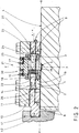
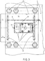
- FIGS. 2 and 3 show an improved and simplified device in an embodiment corresponding to the invention and can be seen from the synopsis thereof.
- the cylinder housing (21) in a symmetrical configuration, has outlets (22, 23) on both sides of a plane (yy) that intersects it perpendicularly, for an extended piston rod (24) that can be guided in both directions of movement according to the double arrow (14) and has an approximately pistons (25) which can be loaded on both sides in the center.
- the locking plate (11) and the locking guide (10) have a window-like recess (1) that corresponds at least to the length of the piston rod (24) and the width of the cylinder housing (21).
- the cylinder housing (21) with loose contact of both piston rod ends (26, 27) is arranged on both mutually opposite surfaces (2, 3) which run transversely to the direction of movement of the locking plate. It is fixed with a centering (15) on the roller stand (4) or on another assembly level.
- the locking plate (11) is to the left through the piston rod (24) or the piston rod end (26) advanced and engages z. B. in a recess (40) of a chock (41) of a roller, for example a backup roller.
- the arrangement of the recess (1) in the locking plate (11) and in the locking guide (10) can be seen in particular from FIG.
- the displacement position of the locking plate (11) to the left can be recognized by the piston rod (24) emerging from the cylinder housing (21) to the left. This is supported loosely with the piston rod end (26) against the surface (2) of the recess (1) in the locking plate (11), while the opposite piston rod end (27) is in loose contact with the surface (3) of the recess (1) follows.
- the number (4) indicates the surface of the roll stand or another assembly level, depending on which part of the roll stand or other systems the device is arranged.
- the locking plate (11) is designed to be able to interact directly without mechanical connection with the piston / cylinder unit (20, 21) or with its piston rod ends (26, 27).
- the cylinder housing (21) has flow channels (16, 17) for a working medium in the upper region and a centering projection (15) which can be engaged in a compatible centering recess (5) in the lower region as shown in FIG. 2.
- the piston rod guide (19) with holding cover (18) is arranged for easy maintenance.
- the locking plate (11) has lubricant channels (8, 9) to form a hydrostatic lubricant sliding layer. This almost eliminates the sliding friction between the locking plate (11) and the guide (4, 10) and enables easy sliding with practically maintenance-free and unlimited availability of the device.
- the lubricant channels (8, 9) can be seen both from FIG. 2 and from FIG. 3 and therein in particular in their arrangement transverse to the direction of movement of the locking plate (11) according to the arrow (14).
- FIG. 4 shows an exemplary arrangement of two devices (50 or 51) for axially locking support rollers (31, 32). From this it can be seen that the devices (50 and 51) can be easily integrated into the rolling stand or other systems due to their uncomplicated design and can be arranged there with little effort and construction volume.
- FIGS. 2 and 3 The embodiment of the device according to the invention shown in FIGS. 2 and 3 is merely of an exemplary nature, wherein Modified versions are also within the scope of the invention, provided that they correspond to the construction principle of the main claim.
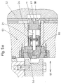
- FIGS. 5a and 5b An arrangement of the locking device within a CVC displacement device is shown in FIGS. 5a and 5b.
- the locking plate (11) is guided hydraulically or pneumatically in one or the other direction of the double arrow (55) in a recess (54) of the sliding block (53) by the piston rod (24) of the cylinder housing (21) and moves and engages one of its ends (56) or (57) one time in the recess (51) of the work roll component (50) or the other time in the recess (58) of the fixed block (52).
- the cylinder housing (21) is very advantageously attached to one of the piston rod exit surfaces (60). In the example shown, this is a wide flange (60) which rests on both sides on shoulders of the displacement block (53) within the recess (51) and is screwed to it, for example.
- the locking plate (11) thus locks the sliding block (53) with the work roll component (50) during the rolling operation.
- the sliding block (53) can be locked with the fixed block (52), thereby preventing its unwanted movement (FIG. 5b).
Landscapes
- Engineering & Computer Science (AREA)
- Mechanical Engineering (AREA)
- Actuator (AREA)
- Road Paving Machines (AREA)
Applications Claiming Priority (4)
| Application Number | Priority Date | Filing Date | Title |
|---|---|---|---|
| DE19541883 | 1995-11-10 | ||
| DE19541883 | 1995-11-10 | ||
| DE19637060 | 1996-09-12 | ||
| DE19637060A DE19637060A1 (de) | 1995-11-10 | 1996-09-12 | Vorrichtung zur axialen Verriegelung von Stütz-, Arbeits- und/oder Zwischenwalzen in einem Walzgerüst oder anderen Systemen |
Publications (3)
| Publication Number | Publication Date |
|---|---|
| EP0773073A2 true EP0773073A2 (fr) | 1997-05-14 |
| EP0773073A3 EP0773073A3 (fr) | 1998-05-20 |
| EP0773073B1 EP0773073B1 (fr) | 2003-02-12 |
Family
ID=26020240
Family Applications (1)
| Application Number | Title | Priority Date | Filing Date |
|---|---|---|---|
| EP96117727A Expired - Lifetime EP0773073B1 (fr) | 1995-11-10 | 1996-11-06 | Dispositif pour le blocage axial de cylindres d'appui, de travail et/ou intermédiaires dans une cage de laminoir ou autres systèmes |
Country Status (3)
| Country | Link |
|---|---|
| EP (1) | EP0773073B1 (fr) |
| AT (1) | ATE232426T1 (fr) |
| ES (1) | ES2192594T3 (fr) |
Cited By (1)
| Publication number | Priority date | Publication date | Assignee | Title |
|---|---|---|---|---|
| CN110733762A (zh) * | 2019-11-09 | 2020-01-31 | 中冶南方(新余)冷轧新材料技术有限公司 | 一种轧机用锁止装置 |
Families Citing this family (1)
| Publication number | Priority date | Publication date | Assignee | Title |
|---|---|---|---|---|
| DE102011082372A1 (de) | 2011-09-08 | 2013-03-14 | Sms Siemag Ag | Kombinierte Walzenverriegelung/Antriebsspindelhalterung für Walzanlagen |
Family Cites Families (4)
| Publication number | Priority date | Publication date | Assignee | Title |
|---|---|---|---|---|
| FR1122538A (fr) * | 1954-04-15 | 1956-09-10 | Schloemann Ag | Dispositif pour immobiliser et déplacer dans la cage, dans le sens axial, des cylindres de laminoir ou des pièces de montage |
| DE3331055C2 (de) * | 1983-08-29 | 1994-11-03 | Schloemann Siemag Ag | Walzgerüst mit axial verschieblichen Arbeitswalzen |
| GB8528849D0 (en) * | 1985-11-22 | 1985-12-24 | Davy Mckee Poole | Rolling mill stands |
| JPH03207513A (ja) * | 1990-01-08 | 1991-09-10 | Hitachi Ltd | 圧延機のロールシフトブロツククランプ装置 |
-
1996
- 1996-11-06 AT AT96117727T patent/ATE232426T1/de active
- 1996-11-06 ES ES96117727T patent/ES2192594T3/es not_active Expired - Lifetime
- 1996-11-06 EP EP96117727A patent/EP0773073B1/fr not_active Expired - Lifetime
Non-Patent Citations (1)
| Title |
|---|
| None |
Cited By (1)
| Publication number | Priority date | Publication date | Assignee | Title |
|---|---|---|---|---|
| CN110733762A (zh) * | 2019-11-09 | 2020-01-31 | 中冶南方(新余)冷轧新材料技术有限公司 | 一种轧机用锁止装置 |
Also Published As
| Publication number | Publication date |
|---|---|
| ATE232426T1 (de) | 2003-02-15 |
| ES2192594T3 (es) | 2003-10-16 |
| EP0773073A3 (fr) | 1998-05-20 |
| EP0773073B1 (fr) | 2003-02-12 |
Similar Documents
| Publication | Publication Date | Title |
|---|---|---|
| EP0983897B1 (fr) | Dispositif de levage | |
| DE8915859U1 (de) | Vorrichtung zum Einleiten einer Hubbewegung in einer Hubmechanik | |
| DE2456839C2 (de) | Schaltorgan | |
| DE69913882T2 (de) | Laufkran | |
| DE1503119A1 (de) | Bearbeitungsvorrichtung | |
| DE60203128T2 (de) | Universalwalzgerüst mit walzspaltregelung | |
| DE3843387A1 (de) | Vorrichtung zum walzenwechsel insbesondere der horizontal verschieblichen arbeitswalzen in einem walzgeruest | |
| DE2148966C3 (de) | Teleskopausleger, insbesondere für straßenverfahrbare Krane | |
| DE2730959A1 (de) | Zuspannvorrichtung fuer reibungsbremsen, insbesondere von schienenfahrzeugen | |
| DE3331055A1 (de) | Walzgeruest mit axial verschieblichen arbeitswalzen | |
| DE3107693A1 (de) | Walzgeruest | |
| EP0773073B1 (fr) | Dispositif pour le blocage axial de cylindres d'appui, de travail et/ou intermédiaires dans une cage de laminoir ou autres systèmes | |
| DE2232709A1 (de) | Betaetigungs- oder kraftverstaerkungseinrichtung | |
| EP0271880A2 (fr) | Support à colonne et bras articulé sur celle-ci | |
| DE19637060A1 (de) | Vorrichtung zur axialen Verriegelung von Stütz-, Arbeits- und/oder Zwischenwalzen in einem Walzgerüst oder anderen Systemen | |
| DE3907440C2 (fr) | ||
| DE1940414B2 (de) | Walzgerüst mit einer Einrichtung zum Walzenwechsel | |
| DE3627692A1 (de) | Biege- und ausbalanciervorrichtung fuer axial verschiebbare arbeitswalzen eines quartowalzgeruestes | |
| DE3105702A1 (de) | Kolben-pleuel-verbindung fuer hubkolbenmaschinen, insbesondere zweitakt-brennkraftmaschinen | |
| DE2645290C2 (de) | Vorrichtung zur Linearführung, insbesondere Geradführung | |
| WO2005058546A1 (fr) | Tete de rouleau de cylindrage pour vilebrequin a goupille d'arret | |
| DE102004042335A1 (de) | Flurförderzeug mit Gleitführung in der Lastverlagerungsvorrichtung | |
| EP0124796A1 (fr) | Mécanisme de mâchoires de serrage pour un appareil tire-câble hydraulique travaillant pas à pas | |
| DE2220164C3 (de) | Reiheneinspritzpumpe für Brennkraftmaschinen | |
| EP0233460B1 (fr) | Dispositif pour fléchir les cylindres à déplacement axial d'une cage de laminoir |
Legal Events
| Date | Code | Title | Description |
|---|---|---|---|
| PUAI | Public reference made under article 153(3) epc to a published international application that has entered the european phase |
Free format text: ORIGINAL CODE: 0009012 |
|
| 17P | Request for examination filed |
Effective date: 19961113 |
|
| AK | Designated contracting states |
Kind code of ref document: A2 Designated state(s): AT BE DE ES FI FR GB IT NL SE |
|
| PUAL | Search report despatched |
Free format text: ORIGINAL CODE: 0009013 |
|
| AK | Designated contracting states |
Kind code of ref document: A3 Designated state(s): AT BE DE ES FI FR GB IT NL SE |
|
| RAP1 | Party data changed (applicant data changed or rights of an application transferred) |
Owner name: SMS DEMAG AG |
|
| 17Q | First examination report despatched |
Effective date: 20010629 |
|
| GRAG | Despatch of communication of intention to grant |
Free format text: ORIGINAL CODE: EPIDOS AGRA |
|
| GRAG | Despatch of communication of intention to grant |
Free format text: ORIGINAL CODE: EPIDOS AGRA |
|
| GRAH | Despatch of communication of intention to grant a patent |
Free format text: ORIGINAL CODE: EPIDOS IGRA |
|
| GRAH | Despatch of communication of intention to grant a patent |
Free format text: ORIGINAL CODE: EPIDOS IGRA |
|
| GRAA | (expected) grant |
Free format text: ORIGINAL CODE: 0009210 |
|
| AK | Designated contracting states |
Designated state(s): AT BE DE ES FI FR GB IT NL SE |
|
| REG | Reference to a national code |
Ref country code: GB Ref legal event code: FG4D Free format text: NOT ENGLISH |
|
| REF | Corresponds to: |
Ref document number: 59610125 Country of ref document: DE Date of ref document: 20030320 Kind code of ref document: P |
|
| GBT | Gb: translation of ep patent filed (gb section 77(6)(a)/1977) | ||
| ET | Fr: translation filed | ||
| REG | Reference to a national code |
Ref country code: ES Ref legal event code: FG2A Ref document number: 2192594 Country of ref document: ES Kind code of ref document: T3 |
|
| PLBE | No opposition filed within time limit |
Free format text: ORIGINAL CODE: 0009261 |
|
| STAA | Information on the status of an ep patent application or granted ep patent |
Free format text: STATUS: NO OPPOSITION FILED WITHIN TIME LIMIT |
|
| 26N | No opposition filed |
Effective date: 20031113 |
|
| PGFP | Annual fee paid to national office [announced via postgrant information from national office to epo] |
Ref country code: SE Payment date: 20111128 Year of fee payment: 16 Ref country code: NL Payment date: 20111124 Year of fee payment: 16 |
|
| PGFP | Annual fee paid to national office [announced via postgrant information from national office to epo] |
Ref country code: BE Payment date: 20111110 Year of fee payment: 16 |
|
| BERE | Be: lapsed |
Owner name: *SMS DEMAG A.G. Effective date: 20121130 |
|
| REG | Reference to a national code |
Ref country code: NL Ref legal event code: V1 Effective date: 20130601 |
|
| PG25 | Lapsed in a contracting state [announced via postgrant information from national office to epo] |
Ref country code: SE Free format text: LAPSE BECAUSE OF NON-PAYMENT OF DUE FEES Effective date: 20121107 |
|
| PG25 | Lapsed in a contracting state [announced via postgrant information from national office to epo] |
Ref country code: BE Free format text: LAPSE BECAUSE OF NON-PAYMENT OF DUE FEES Effective date: 20121130 Ref country code: NL Free format text: LAPSE BECAUSE OF NON-PAYMENT OF DUE FEES Effective date: 20130601 |
|
| REG | Reference to a national code |
Ref country code: DE Ref legal event code: R082 Ref document number: 59610125 Country of ref document: DE Representative=s name: HEMMERICH & KOLLEGEN, DE Ref country code: DE Ref legal event code: R081 Ref document number: 59610125 Country of ref document: DE Owner name: SMS GROUP GMBH, DE Free format text: FORMER OWNER: SMS SIEMAG AKTIENGESELLSCHAFT, 40237 DUESSELDORF, DE |
|
| REG | Reference to a national code |
Ref country code: FR Ref legal event code: PLFP Year of fee payment: 20 |
|
| PGFP | Annual fee paid to national office [announced via postgrant information from national office to epo] |
Ref country code: FI Payment date: 20151111 Year of fee payment: 20 Ref country code: IT Payment date: 20151125 Year of fee payment: 20 Ref country code: DE Payment date: 20151119 Year of fee payment: 20 Ref country code: GB Payment date: 20151118 Year of fee payment: 20 |
|
| PGFP | Annual fee paid to national office [announced via postgrant information from national office to epo] |
Ref country code: AT Payment date: 20151119 Year of fee payment: 20 Ref country code: FR Payment date: 20151119 Year of fee payment: 20 Ref country code: ES Payment date: 20151111 Year of fee payment: 20 |
|
| REG | Reference to a national code |
Ref country code: DE Ref legal event code: R071 Ref document number: 59610125 Country of ref document: DE |
|
| REG | Reference to a national code |
Ref country code: GB Ref legal event code: PE20 Expiry date: 20161105 |
|
| REG | Reference to a national code |
Ref country code: AT Ref legal event code: MK07 Ref document number: 232426 Country of ref document: AT Kind code of ref document: T Effective date: 20161106 |
|
| PG25 | Lapsed in a contracting state [announced via postgrant information from national office to epo] |
Ref country code: GB Free format text: LAPSE BECAUSE OF EXPIRATION OF PROTECTION Effective date: 20161105 |
|
| REG | Reference to a national code |
Ref country code: ES Ref legal event code: FD2A Effective date: 20170224 |
|
| PG25 | Lapsed in a contracting state [announced via postgrant information from national office to epo] |
Ref country code: ES Free format text: LAPSE BECAUSE OF EXPIRATION OF PROTECTION Effective date: 20161107 |