EP0773073A2 - Device for locking the axis of back-up rolls, work rolls and/or intermediate rolls in a rolling stand or in other systems - Google Patents
Device for locking the axis of back-up rolls, work rolls and/or intermediate rolls in a rolling stand or in other systems Download PDFInfo
- Publication number
- EP0773073A2 EP0773073A2 EP96117727A EP96117727A EP0773073A2 EP 0773073 A2 EP0773073 A2 EP 0773073A2 EP 96117727 A EP96117727 A EP 96117727A EP 96117727 A EP96117727 A EP 96117727A EP 0773073 A2 EP0773073 A2 EP 0773073A2
- Authority
- EP
- European Patent Office
- Prior art keywords
- locking plate
- piston rod
- locking
- cylinder housing
- rolls
- Prior art date
- Legal status (The legal status is an assumption and is not a legal conclusion. Google has not performed a legal analysis and makes no representation as to the accuracy of the status listed.)
- Granted
Links
- 238000005096 rolling process Methods 0.000 title description 3
- 238000006073 displacement reaction Methods 0.000 claims description 5
- 239000000314 lubricant Substances 0.000 claims description 5
- 238000005452 bending Methods 0.000 claims description 2
- 230000002706 hydrostatic effect Effects 0.000 claims description 2
- 239000012791 sliding layer Substances 0.000 claims description 2
- 238000012423 maintenance Methods 0.000 description 4
- 238000010276 construction Methods 0.000 description 3
- 230000010354 integration Effects 0.000 description 3
- 102000004315 Forkhead Transcription Factors Human genes 0.000 description 2
- 108090000852 Forkhead Transcription Factors Proteins 0.000 description 2
- 238000004519 manufacturing process Methods 0.000 description 2
- 238000013016 damping Methods 0.000 description 1
Images



Classifications
-
- B—PERFORMING OPERATIONS; TRANSPORTING
- B21—MECHANICAL METAL-WORKING WITHOUT ESSENTIALLY REMOVING MATERIAL; PUNCHING METAL
- B21B—ROLLING OF METAL
- B21B31/00—Rolling stand structures; Mounting, adjusting, or interchanging rolls, roll mountings, or stand frames
- B21B31/16—Adjusting or positioning rolls
- B21B31/18—Adjusting or positioning rolls by moving rolls axially
Definitions
- the invention relates to a device for the axial locking of support, work and / or intermediate rolls in a roll stand or other systems with locking characteristics, for example a CVC roll stand, with a mountable for support rolls on the roll stand and for work and intermediate rolls on the bending system or roll stand , a locking plate having a locking guide and with a for the actuation of the locking plate on the one hand on this, on the roller stand or on another mounting level arranged hydraulic piston / cylinder unit.
- a disadvantage of this known or a similar type of construction is, on the one hand, the overall height, which restricts the available space for arranging, for example, scaffolding piping and / or for other components.
- Another disadvantage is the number of components required, such as a rod head with a spherical bearing, a support frame, a cylinder with a pivot rod and a spherical bearing, bolts and securing elements, hydraulic hoses, special screws and washers. Overall, this results in a comparatively high outlay for production, assembly and maintenance.
- the point of action of the piston / cylinder unit in a plane of attack that is spaced apart from the guide level causes a harmful tilting moment of the locking plate in its guide, which is therefore particularly susceptible to wear and requires maintenance, and can also tend to jam at most.
- the invention has for its object to significantly simplify the device of the type mentioned, both in terms of the number of components required and their design, with the aim of drastically reducing the cost of manufacture, assembly and maintenance.
- this device has a locking plate (11) arranged on the mounting plane (zz) of a roll stand (4), which in the guide formed between the plane (zz) and the guide elements (13) is displaceable in the direction of the double arrow (14) and is designed, for example, to be able to engage in an engagement recess (40) in the chock of a roller.
- a fork head on the locking plate (11) (34) is arranged, while on the assembly level (zz) of the roller stand (4) a support bracket (36) is provided.
- the hydraulic piston / cylinder unit with the cylinder housing (21) with swivel rod, rod head and spherical bearing (35) and (37) is articulated.
- This arrangement has the disadvantages mentioned above.
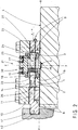
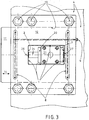
- FIGS. 2 and 3 show an improved and simplified device in an embodiment corresponding to the invention and can be seen from the synopsis thereof.
- the cylinder housing (21) in a symmetrical configuration, has outlets (22, 23) on both sides of a plane (yy) that intersects it perpendicularly, for an extended piston rod (24) that can be guided in both directions of movement according to the double arrow (14) and has an approximately pistons (25) which can be loaded on both sides in the center.
- the locking plate (11) and the locking guide (10) have a window-like recess (1) that corresponds at least to the length of the piston rod (24) and the width of the cylinder housing (21).
- the cylinder housing (21) with loose contact of both piston rod ends (26, 27) is arranged on both mutually opposite surfaces (2, 3) which run transversely to the direction of movement of the locking plate. It is fixed with a centering (15) on the roller stand (4) or on another assembly level.
- the locking plate (11) is to the left through the piston rod (24) or the piston rod end (26) advanced and engages z. B. in a recess (40) of a chock (41) of a roller, for example a backup roller.
- the arrangement of the recess (1) in the locking plate (11) and in the locking guide (10) can be seen in particular from FIG.
- the displacement position of the locking plate (11) to the left can be recognized by the piston rod (24) emerging from the cylinder housing (21) to the left. This is supported loosely with the piston rod end (26) against the surface (2) of the recess (1) in the locking plate (11), while the opposite piston rod end (27) is in loose contact with the surface (3) of the recess (1) follows.
- the number (4) indicates the surface of the roll stand or another assembly level, depending on which part of the roll stand or other systems the device is arranged.
- the locking plate (11) is designed to be able to interact directly without mechanical connection with the piston / cylinder unit (20, 21) or with its piston rod ends (26, 27).
- the cylinder housing (21) has flow channels (16, 17) for a working medium in the upper region and a centering projection (15) which can be engaged in a compatible centering recess (5) in the lower region as shown in FIG. 2.
- the piston rod guide (19) with holding cover (18) is arranged for easy maintenance.
- the locking plate (11) has lubricant channels (8, 9) to form a hydrostatic lubricant sliding layer. This almost eliminates the sliding friction between the locking plate (11) and the guide (4, 10) and enables easy sliding with practically maintenance-free and unlimited availability of the device.
- the lubricant channels (8, 9) can be seen both from FIG. 2 and from FIG. 3 and therein in particular in their arrangement transverse to the direction of movement of the locking plate (11) according to the arrow (14).
- FIG. 4 shows an exemplary arrangement of two devices (50 or 51) for axially locking support rollers (31, 32). From this it can be seen that the devices (50 and 51) can be easily integrated into the rolling stand or other systems due to their uncomplicated design and can be arranged there with little effort and construction volume.
- FIGS. 2 and 3 The embodiment of the device according to the invention shown in FIGS. 2 and 3 is merely of an exemplary nature, wherein Modified versions are also within the scope of the invention, provided that they correspond to the construction principle of the main claim.
- FIGS. 5a and 5b An arrangement of the locking device within a CVC displacement device is shown in FIGS. 5a and 5b.
- the locking plate (11) is guided hydraulically or pneumatically in one or the other direction of the double arrow (55) in a recess (54) of the sliding block (53) by the piston rod (24) of the cylinder housing (21) and moves and engages one of its ends (56) or (57) one time in the recess (51) of the work roll component (50) or the other time in the recess (58) of the fixed block (52).
- the cylinder housing (21) is very advantageously attached to one of the piston rod exit surfaces (60). In the example shown, this is a wide flange (60) which rests on both sides on shoulders of the displacement block (53) within the recess (51) and is screwed to it, for example.
- the locking plate (11) thus locks the sliding block (53) with the work roll component (50) during the rolling operation.
- the sliding block (53) can be locked with the fixed block (52), thereby preventing its unwanted movement (FIG. 5b).
Landscapes
- Engineering & Computer Science (AREA)
- Mechanical Engineering (AREA)
- Actuator (AREA)
- Road Paving Machines (AREA)
Abstract
Description
Die Erfindung betrifft eine Vorrichtung zur axialen Verriegelung von Stütz-, Arbeits- und/oder Zwischenwalzen in einem Walzgerüst oder anderen Systemen mit Verriegelungscharakteristik, beispielsweise einem CVC-Walzgerüst, mit einer für Stützwalzen am Walzenständer und für Arbeits- und Zwischenwalzen am Biegesystem oder Walzenständer befestigbaren, eine Riegelplatte aufweisenden Riegelführung sowie mit einer für die Betätigung der Riegelplatte einerseits an dieser, am Walzenständer bzw. an einer anderen Montageebene angreifbar angeordneten hydraulischen Kolben/Zylinder-Einheit.The invention relates to a device for the axial locking of support, work and / or intermediate rolls in a roll stand or other systems with locking characteristics, for example a CVC roll stand, with a mountable for support rolls on the roll stand and for work and intermediate rolls on the bending system or roll stand , a locking plate having a locking guide and with a for the actuation of the locking plate on the one hand on this, on the roller stand or on another mounting level arranged hydraulic piston / cylinder unit.
Vorrichtungen zur axialen Verriegelung von Stütz-, Arbeits- und/oder Zwischenwalzen in einem Walzgerüst sind seit langem bekannt. Bei diesen hat sich eine praxisübliche Bauart herausgebildet, bei der einerseits an der Riegelplatte entsprechend einer in der Figur 1 gezeigten beispielhaften Ausführung vom Stand der Technik ein die Riegelplattenführung überragender Gabelkopf und andererseits an der Anbauebene des Walzenständers oder des Biegesystems neben der Vorrichtung ein Stützbock angebracht und zwischen diesen in einer zur Riegelplatte parallelen Ebene die Kolben/Zylinder-Einheit mit Stangenkopf und Gelenklager angelenkt ist.Devices for the axial locking of support, work and / or intermediate rolls in a roll stand have long been known. A practical design has developed in this case, in which, on the one hand, a fork head protruding beyond the locking plate guide, on the locking plate corresponding to an exemplary embodiment from the prior art shown in FIG Support bracket attached and the piston / cylinder unit with rod head and spherical bearing is articulated between them in a plane parallel to the locking plate.
Von Nachteil bei dieser bekannten oder einer ähnlichen Bauart ist einerseits die Bauhöhe, welche den verfügbaren Platz zur Anordnung beispielsweise einer Gerüstverrohrung und/oder für andere Bauteile einengt.A disadvantage of this known or a similar type of construction is, on the one hand, the overall height, which restricts the available space for arranging, for example, scaffolding piping and / or for other components.
Nachteilig ist weiterhin die Anzahl der benötigten Bauteile wie Stangenkopf mit Gelenklager, Stützbock, Zylinder mit Schwenkstange und Gelenklager, Bolzen und Sicherungselemente, Hydraulikschläuche, Spezialschrauben und Scheiben. Dies ergibt insgesamt einen vergleichsweise hohen Aufwand für Fertigung, Montage und Wartung.Another disadvantage is the number of components required, such as a rod head with a spherical bearing, a support frame, a cylinder with a pivot rod and a spherical bearing, bolts and securing elements, hydraulic hoses, special screws and washers. Overall, this results in a comparatively high outlay for production, assembly and maintenance.
Und nicht zuletzt verursacht der Angriffspunkt der Kolben/Zylinder-Einheit in einer zur Führungsebene beabstandeten Angriffsebene ein schädliches Kippmoment der Riegelplatte in ihrer Führung, die dadurch insbesondere bei Anfall von Verschmutzung verschleißträchtig und wartungsbedürftig ist und äußerstenfalls auch zum Klemmen neigen kann.And last but not least, the point of action of the piston / cylinder unit in a plane of attack that is spaced apart from the guide level causes a harmful tilting moment of the locking plate in its guide, which is therefore particularly susceptible to wear and requires maintenance, and can also tend to jam at most.
Der Erfindung liegt die Aufgabe zugrunde, die Vorrichtung der eingangs genannten Bauart wesentlich zu vereinfachen, und zwar sowohl hinsichtlich der Anzahl benötigter Bauteile als auch ihrer konstruktiven Ausbildung, mit dem Ziel, die Kosten für Fertigung, Montage und Wartung drastisch zu reduzieren.The invention has for its object to significantly simplify the device of the type mentioned, both in terms of the number of components required and their design, with the aim of drastically reducing the cost of manufacture, assembly and maintenance.
Zur Lösung wird bei einer Vorrichtung der im Oberbegriff von Anspruch 1 genannten Art mit der Erfindung vorgeschlagen,
- daß das Zylindergehäuse in symmetrischer Anordnung zu beiden Seiten einer es senkrecht schneidenden Ebene Austritte für eine nach beiden Seiten austretbar geführte Kolbenstange mit einem etwa mittig daran befestigten, beidseitig beaufschlagbaren Kolben aufweist,
- daß die Riegelplatte und Riegelführung eine zumindest der Länge der Kolbenstange sowie der Breite des Zylindergehäuses entsprechende fensterartige Ausnehmung aufweist, und
- daß das Zylindergehäuse innerhalb dieser Ausnehmung mit losem Kontakt der Kolbenstangenenden an beiden zur Bewegungsrichtung der Riegelplatte quer verlaufenden, einander entgegengerichteten Flächen der Ausnehmung auf der Montageebene fixiert oder bei Integration in CVC-Verschiebeblöcken an einer der Kolbenstangen-Austrittsflächen befestigt ist.
- that the cylinder housing, in a symmetrical arrangement on both sides of a plane intersecting it vertically, has outlets for a piston rod guided to be able to exit on both sides, with a piston attached approximately centrally to it, which can be acted upon on both sides,
- that the locking plate and locking guide have at least the length of the piston rod and the width of the cylinder housing corresponding window-like recess, and
- that the cylinder housing is fixed within this recess with loose contact of the piston rod ends on both transverse to the direction of movement of the locking plate, mutually opposing surfaces of the recess on the mounting plane or attached to one of the piston rod exit surfaces when integrated in CVC displacement blocks.
Mit der erfindungsgemäßen Ausführung der Vorrichtung ergeben sich gegenüber der bekannten Ausführung folgende Vorteile:
- a) eine wesentliche Reduzierung der Bauhöhe, dadurch ein verbessertes Platzangebot für Gerüstverrohrung und Anordnung anderer Bauteile, sowie die Möglichkeit der Integration in CVC-Vorschiebesysteme.
- b) die unmittelbare Krafteinleitung der Kolbenstangenenden in die Riegelplatte in beiden Bewegungsrichtungen vermeidet ein schädliches Kippmoment der Riegelplatte in ihrer Führung, die infolgedessen leichtgängig, verschleißarm und wartungsfreundlich ist und in keinem Fall zum Klemmen neigt. Insgesamt wird dadurch die Vorrichtung servicefreundlicher bei unproblematischer Austauschbarkeit der Riegelplatten des Zylinders.
- c) infolge Bauteilreduzierung ergibt sich eine Einsparung von
- Zylinderhalterung
- Stangenkopf mit Gelenklager
- Stützbock
- Bolzen und Sicherungselementen
- Spezialschrauben und Scheiben
- Arbeitszylinder mit Schwenkzapfen
- Hydraulikschläuchen
- d) ein im Detail stark vereinfachter Arbeitszylinder
- ohne Dämpfung
- ohne Gelenklager
- mit einer Kolbenstange ohne Gewinde
- mit vereinfachtem Zylinderkörper ohne Ansätze.
- a) a significant reduction in the overall height, thereby an improved space for scaffolding piping and arrangement of other components, as well as the possibility of integration in CVC feed systems.
- b) the direct introduction of force of the piston rod ends into the locking plate in both directions of movement avoids a harmful tilting moment of the locking plate in its guidance, which as a result is smooth-running, low-wear and easy to maintain and in no case tends to jam. All in all, this makes the device more service-friendly and the locking plates of the cylinder can be exchanged without problems.
- c) as a result of component reduction, there is a saving of
- Cylinder holder
- Rod head with spherical bearing
- Trestle
- Bolts and securing elements
- Special screws and washers
- Working cylinder with pivot pin
- Hydraulic hoses
- d) a working cylinder that is greatly simplified in detail
- without damping
- without spherical bearings
- with a piston rod without thread
- with a simplified cylinder body without lugs.
Beim Einsatz der Vorrichtung in bekannten CVC-Verschiebesystemen übernimmt der Verschiebeblock selbst die Riegelführung.When the device is used in known CVC sliding systems, the sliding block itself takes over the bolt guidance.
Vorteilhafte Ausgestaltungen sind entsprechend den Unteransprüchen vorgesehen. Weitere Einzelheiten, Merkmale und Vorteile der Erfindung ergeben sich aus der nachstehenden Erläuterung eines in den Zeichnungen schematisch dargestelltem Ausführungsbeispieles.Advantageous configurations are provided in accordance with the subclaims. Further details, features and advantages of the invention result from the following explanation of an exemplary embodiment shown schematically in the drawings.
Es zeigen:
- Fig. 1
- in Seitenansicht und teilweise im Schnitt eine Ausführung der Vorrichtung nach dem Stand der Technik,
- Fig. 2
- im Schnitt sowie in Seitenansicht eine Ausführung der Vorrichtung nach der Erfindung,
- Fig. 3
- die Vorrichtung gemäß Fig. 2 in Draufsicht,
- Fig. 4
- eine Ansicht eines Walzenständers von der Seite mit am Ständer angeordneten Vorrichtungen für die Stützwalzenverriegelung,
- Fig. 5a
- die Vorrichtung mit Anordnung in einem CVC-Verschiebesystem bei Verriegelung mit dem Festblock im Schnitt,
- Fig. 5b
- die Vorrichtung gemäß Fig. 5a bei Verriegelung mit dem Arbeitswalzenbaustück im Schnitt.
- Fig. 1
- in side view and partly in section an embodiment of the device according to the prior art,
- Fig. 2
- in section and in side view an embodiment of the device according to the invention,
- Fig. 3
- 2 in top view,
- Fig. 4
- 2 shows a view of a roller stand from the side with devices for the backup roller locking arranged on the stand,
- Fig. 5a
- the device with arrangement in a CVC shifting system when locked with the fixed block on average,
- Fig. 5b
- the device of FIG. 5a when locked with the work roll component in section.
Bei der in Figur 1 gezeigten Ausführung einer Vorrichtung zur axialen Verriegelung von Stütz-, Arbeits- und/oder Zwischenwalzen nach dem Stand der Technik weist diese eine an der Montageebene (z-z) eines Walzenständers (4) angeordnete Riegelplatte (11) auf, die in der zwischen der Ebene (z-z) und den Führungselementen (13) ausgebildeten Führung in Richtung des Doppelpfeiles (14) verschiebbar und beispielsweise in eine Eingriffvertiefung (40) im Einbaustück einer Walze eingreifbar ausgebildet ist. Auf der Riegelplatte (11) ist ein Gabelkopf (34) angeordnet, während entgegengesetzt dazu an der Montageebene (z-z) des Walzenständers (4) ein Stützbock (36) vorgesehen ist. Zwischen diesen ist die hydraulische Kolben/Zylinder-Einheit mit dem Zylindergehäuse (21) mit Schwenkstange, Stangenkopf und Gelenklager (35) und (37) gelenkig angeordnet. Diese Anordnung weist die vorstehend angegebenen Nachteile auf.In the embodiment of a device for axially locking support, work and / or intermediate rolls according to the prior art shown in FIG. 1, this device has a locking plate (11) arranged on the mounting plane (zz) of a roll stand (4), which in the guide formed between the plane (zz) and the guide elements (13) is displaceable in the direction of the double arrow (14) and is designed, for example, to be able to engage in an engagement recess (40) in the chock of a roller. There is a fork head on the locking plate (11) (34) is arranged, while on the assembly level (zz) of the roller stand (4) a support bracket (36) is provided. Between these, the hydraulic piston / cylinder unit with the cylinder housing (21) with swivel rod, rod head and spherical bearing (35) and (37) is articulated. This arrangement has the disadvantages mentioned above.
In den Figuren 2 und 3 ist eine verbesserte und vereinfachte Vorrichtung in einer der Erfindung entsprechenden Ausführung gezeigt und aus deren Zusammenschau erkennbar. Bei dieser Ausführung weist das Zylindergehäuse (21) in symmetrischer Ausbildung zu beiden Seiten einer es senkrecht schneidenden Ebene (y-y) Austritte (22, 23) für eine in beiden Bewegungsrichtungen gemäß dem Doppelpfeil (14) austretbar geführte verlängerte Kolbenstange (24) mit einem etwa mittig daran befestigten, beidseitig beaufschlagbaren Kolben (25) auf.FIGS. 2 and 3 show an improved and simplified device in an embodiment corresponding to the invention and can be seen from the synopsis thereof. In this embodiment, the cylinder housing (21), in a symmetrical configuration, has outlets (22, 23) on both sides of a plane (yy) that intersects it perpendicularly, for an extended piston rod (24) that can be guided in both directions of movement according to the double arrow (14) and has an approximately pistons (25) which can be loaded on both sides in the center.
Die Riegelplatte (11) und die Riegelführung (10) weisen eine zumindest der Länge der Kolbenstange (24) sowie der Breite des Zylindergehäuses (21) entsprechende fensterartige Ausnehmung (1) auf.The locking plate (11) and the locking guide (10) have a window-like recess (1) that corresponds at least to the length of the piston rod (24) and the width of the cylinder housing (21).
Innerhalb von dieser Ausnehmung (1) ist das Zylindergehäuse (21) mit losem Kontakt beider Kolbenstangenenden (26, 27) an beiden zur Bewegungsrichtung der Riegelplatte quer verlaufenden, einander entgegengerichteten Flächen (2, 3) angeordnet. Es ist mit einer Zentrierung (15) am Walzenständer (4) oder an einer anderen Montageebene fixiert.Within this recess (1), the cylinder housing (21) with loose contact of both piston rod ends (26, 27) is arranged on both mutually opposite surfaces (2, 3) which run transversely to the direction of movement of the locking plate. It is fixed with a centering (15) on the roller stand (4) or on another assembly level.
In der gezeigten Stellung ist die Riegelplatte (11) nach links durch die Kolbenstange (24) bzw. das Kolbenstangenende (26) vorgeschoben und greift z. B. in eine Ausnehmung (40) eines Einbaustückes (41) einer Walze, beispielsweise einer Stützwalze, ein.In the position shown, the locking plate (11) is to the left through the piston rod (24) or the piston rod end (26) advanced and engages z. B. in a recess (40) of a chock (41) of a roller, for example a backup roller.
Aus der Figur 2 ist die gegenüber dem Stand der Technik wesentlich reduzierte Bauhöhe sowie die unmittelbare Krafteinleitung der Kolbenstange (24) in die Riegelplatte (11) besonders deutlich erkennbar. Ebenfalls deutlich erkennbar ist aus den Figuren 2 und 3, daß die erfindungsgemäße Ausführung der Vorrichtung eine wesentliche Reduzierung von Bauteilen zur Folge hat.From Figure 2, the significantly reduced overall height compared to the prior art and the direct introduction of force of the piston rod (24) into the locking plate (11) can be seen particularly clearly. It can also be clearly seen from FIGS. 2 and 3 that the embodiment of the device according to the invention results in a substantial reduction in components.
Aus der Figur 3 ist insbesondere die Anordnung der Ausnehmung (1) in der Riegelplatte (11) und in der Riegelführung (10) zu erkennen. Im gezeigten Ausführungsbeispiel ist die Verschiebeposition der Riegelplatte (11) nach links durch die aus dem Zylindergehäuse (21) nach links austretende Kolbenstange (24) erkennbar. Diese stützt sich lose mit dem Kolbenstangenende (26) gegen die Fläche (2) der Ausnehmung (1) in der Riegelplatte (11) ab, während das entgegengesetzte Kolbenstangenende (27) in losem Kontakt mit der Fläche (3) der Ausnehmung (1) mitläuft. Mit der Ziffer (4) ist die Oberfläche des Walzenständers oder eine andere Montageebene angedeutet, je nachdem, an welchem Teil des Walzgerüstes oder anderen Systemen die Vorrichtung angeordnet ist.The arrangement of the recess (1) in the locking plate (11) and in the locking guide (10) can be seen in particular from FIG. In the exemplary embodiment shown, the displacement position of the locking plate (11) to the left can be recognized by the piston rod (24) emerging from the cylinder housing (21) to the left. This is supported loosely with the piston rod end (26) against the surface (2) of the recess (1) in the locking plate (11), while the opposite piston rod end (27) is in loose contact with the surface (3) of the recess (1) follows. The number (4) indicates the surface of the roll stand or another assembly level, depending on which part of the roll stand or other systems the device is arranged.
Aus der Draufsicht der Figur 3 ist deutlich zu erkennen, daß die Riegelplatte (11) ohne mechanische Verbindung mit der Kolben/Zylinder-Einheit (20, 21) bzw. mit deren Kolbenstangenenden (26, 27) unmittelbar zusammenwirkbar ausgebildet ist.From the top view of FIG. 3 it can be clearly seen that the locking plate (11) is designed to be able to interact directly without mechanical connection with the piston / cylinder unit (20, 21) or with its piston rod ends (26, 27).
Bei einer bevorzugten Ausbildung der Vorrichtung kann von der Maßnahme Gebrauch gemacht sein, daß das Zylindergehäuse (21) im oberen Bereich Strömungskanäle (16, 17) für ein Arbeitsmedium und im unteren Bereich einen in eine kompatible Zentriervertiefung (5) eingreifbaren Zentrieransatz (15) aufweist, wie dies in Fig. 2 gezeigt ist. Die Kolbenstangenführung (19) mit Haltedeckel (18) ist dabei wartungsfreundlich angeordnet.In a preferred embodiment of the device, use can be made of the measure that the cylinder housing (21) has flow channels (16, 17) for a working medium in the upper region and a centering projection (15) which can be engaged in a compatible centering recess (5) in the lower region as shown in FIG. 2. The piston rod guide (19) with holding cover (18) is arranged for easy maintenance.
Und schließlich kann mit großem Vorteil vorgesehen sein, daß die Riegelplatte (11) Schmiermittelkanäle (8, 9) zur Ausbildung einer hydrostatischen Schmiermittel-Gleitschicht aufweist. Damit wird die Gleitreibung zwischen Riegelplatte (11) und Führung (4, 10) nahezu aufgehoben und ein leichtes Gleiten bei praktisch wartungsloser und unbegrenzter Verfügungsbereitschaft der Vorrichtung erreicht. Die Schmiermittelkanäle (8, 9) sind sowohl aus der Figur 2, als auch aus der Figur 3 und darin insbesondere in ihrer Anordnung quer zur Bewegungsrichtung der Riegelplatte (11) nach dem Pfeil (14) erkennbar.Finally, it can be provided with great advantage that the locking plate (11) has lubricant channels (8, 9) to form a hydrostatic lubricant sliding layer. This almost eliminates the sliding friction between the locking plate (11) and the guide (4, 10) and enables easy sliding with practically maintenance-free and unlimited availability of the device. The lubricant channels (8, 9) can be seen both from FIG. 2 and from FIG. 3 and therein in particular in their arrangement transverse to the direction of movement of the locking plate (11) according to the arrow (14).
In der Figur 4 ist eine beispielhafte Anordnung zweier Vorrichtungen (50, bzw. 51) zur axialen Verriegelung von Stützwalzen (31, 32) gezeigt. Daraus ist zu ersehen, daß sich die Vorrichtungen (50 bzw. 51) infolge ihrer unkomplizierten Bauart problemlos in das Walzgerüst oder andere Systeme integrieren lassen und dort mit geringem Aufwand und Bauvolumen anordenbar sind.FIG. 4 shows an exemplary arrangement of two devices (50 or 51) for axially locking support rollers (31, 32). From this it can be seen that the devices (50 and 51) can be easily integrated into the rolling stand or other systems due to their uncomplicated design and can be arranged there with little effort and construction volume.
Die in den Figuren 2 und 3 gezeigte Ausführung der Vorrichtung nach der Erfindung ist lediglich beispielhafter Art, wobei auch geänderte Ausführungen unter den Schutzumfang der Erfindung fallen, sofern sie dem Konstruktionsprinzip des Hauptanspruchs entsprechen.The embodiment of the device according to the invention shown in FIGS. 2 and 3 is merely of an exemplary nature, wherein Modified versions are also within the scope of the invention, provided that they correspond to the construction principle of the main claim.
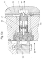
In den Figuren 5a und 5b ist eine Anordnung der Verriegelungsvorrichtung innerhalb einer CVC-Verschiebeeinrichtung gezeigt. Dabei wird die Riegelplatte (11) unmittelbar in einer Ausnehmung (54) des Verschiebeblocks (53) durch die Kolbenstange (24) des Zylindergehäuses (21) hydraulisch oder pneumatisch in der einen oder anderen Richtung des Doppelpfeils (55) geführt und bewegt und greift mit einem ihrer Enden (56) bzw. (57) einmal in die Ausnehmung (51) des Arbeitswalzen-Baustücks (50) oder zum anderenmal in die Ausnehmung (58) des Festblocks (52) ein. Bei dieser Anordnung ist das Zylindergehäuse (21) sehr vorteilhaft an einer der Kolbenstangen-Austrittsflächen (60) befestigt. Diese ist im gezeigten Beispiel ein breiter Flansch (60), der beidseitig auf Schultern des Verschiebeblocks (53) innerhalb der Ausnehmung (51) aufliegt und mit diesem beispielsweise verschraubt ist.An arrangement of the locking device within a CVC displacement device is shown in FIGS. 5a and 5b. The locking plate (11) is guided hydraulically or pneumatically in one or the other direction of the double arrow (55) in a recess (54) of the sliding block (53) by the piston rod (24) of the cylinder housing (21) and moves and engages one of its ends (56) or (57) one time in the recess (51) of the work roll component (50) or the other time in the recess (58) of the fixed block (52). In this arrangement, the cylinder housing (21) is very advantageously attached to one of the piston rod exit surfaces (60). In the example shown, this is a wide flange (60) which rests on both sides on shoulders of the displacement block (53) within the recess (51) and is screwed to it, for example.
Die Riegelplatte (11) verriegelt so während des Walzbetriebes den Verschiebeblock (53) mit dem Arbeitswalzenbaustück (50). Beim Walzenwechsel kann der Verschiebeblock (53) mit dem Festblock (52) verriegelt werden, wodurch dessen ungewollte Bewegung verhindert wird (Fig. 5b).The locking plate (11) thus locks the sliding block (53) with the work roll component (50) during the rolling operation. When changing the roller, the sliding block (53) can be locked with the fixed block (52), thereby preventing its unwanted movement (FIG. 5b).
Claims (5)
Applications Claiming Priority (4)
| Application Number | Priority Date | Filing Date | Title |
|---|---|---|---|
| DE19541883 | 1995-11-10 | ||
| DE19541883 | 1995-11-10 | ||
| DE19637060 | 1996-09-12 | ||
| DE19637060A DE19637060A1 (en) | 1995-11-10 | 1996-09-12 | Device for the axial locking of support, work and / or intermediate rolls in a roll stand or other systems |
Publications (3)
| Publication Number | Publication Date |
|---|---|
| EP0773073A2 true EP0773073A2 (en) | 1997-05-14 |
| EP0773073A3 EP0773073A3 (en) | 1998-05-20 |
| EP0773073B1 EP0773073B1 (en) | 2003-02-12 |
Family
ID=26020240
Family Applications (1)
| Application Number | Title | Priority Date | Filing Date |
|---|---|---|---|
| EP96117727A Expired - Lifetime EP0773073B1 (en) | 1995-11-10 | 1996-11-06 | Device for locking the axis of back-up rolls, work rolls and/or intermediate rolls in a rolling stand or in other systems |
Country Status (3)
| Country | Link |
|---|---|
| EP (1) | EP0773073B1 (en) |
| AT (1) | ATE232426T1 (en) |
| ES (1) | ES2192594T3 (en) |
Cited By (1)
| Publication number | Priority date | Publication date | Assignee | Title |
|---|---|---|---|---|
| CN110733762A (en) * | 2019-11-09 | 2020-01-31 | 中冶南方(新余)冷轧新材料技术有限公司 | locking device for rolling mill |
Families Citing this family (1)
| Publication number | Priority date | Publication date | Assignee | Title |
|---|---|---|---|---|
| DE102011082372A1 (en) | 2011-09-08 | 2013-03-14 | Sms Siemag Ag | Combined roller lock / drive spindle holder for rolling mills |
Family Cites Families (4)
| Publication number | Priority date | Publication date | Assignee | Title |
|---|---|---|---|---|
| FR1122538A (en) * | 1954-04-15 | 1956-09-10 | Schloemann Ag | Device for immobilizing and moving in the stand, in the axial direction, rolling mill rolls or mounting parts |
| DE3331055C2 (en) * | 1983-08-29 | 1994-11-03 | Schloemann Siemag Ag | Roll stand with axially movable work rolls |
| GB8528849D0 (en) * | 1985-11-22 | 1985-12-24 | Davy Mckee Poole | Rolling mill stands |
| JPH03207513A (en) * | 1990-01-08 | 1991-09-10 | Hitachi Ltd | Roll shift block clamp device for rolling mill |
-
1996
- 1996-11-06 AT AT96117727T patent/ATE232426T1/en active
- 1996-11-06 ES ES96117727T patent/ES2192594T3/en not_active Expired - Lifetime
- 1996-11-06 EP EP96117727A patent/EP0773073B1/en not_active Expired - Lifetime
Non-Patent Citations (1)
| Title |
|---|
| None |
Cited By (1)
| Publication number | Priority date | Publication date | Assignee | Title |
|---|---|---|---|---|
| CN110733762A (en) * | 2019-11-09 | 2020-01-31 | 中冶南方(新余)冷轧新材料技术有限公司 | locking device for rolling mill |
Also Published As
| Publication number | Publication date |
|---|---|
| ATE232426T1 (en) | 2003-02-15 |
| ES2192594T3 (en) | 2003-10-16 |
| EP0773073A3 (en) | 1998-05-20 |
| EP0773073B1 (en) | 2003-02-12 |
Similar Documents
| Publication | Publication Date | Title |
|---|---|---|
| EP0983897B1 (en) | Lifting apparatus | |
| DE8915859U1 (en) | Device for initiating a lifting movement in a lifting mechanism | |
| DE2456839C2 (en) | Switching device | |
| DE69913882T2 (en) | overhead crane | |
| DE1503119A1 (en) | Machining device | |
| DE60203128T2 (en) | UNIVERSAL ROLLING RACK WITH ROLLERS | |
| DE3843387A1 (en) | Device for changing rolls, particularly the horizontally displaceable work rolls in a rolling stand | |
| DE2148966C3 (en) | Telescopic boom, especially for road-traveling cranes | |
| DE2730959A1 (en) | CLAMPING DEVICE FOR FRICTION BRAKES, IN PARTICULAR OF RAIL VEHICLES | |
| DE3331055A1 (en) | Roll stand with axially displaceable work rolls | |
| DE3107693A1 (en) | Rolling stand | |
| EP0773073B1 (en) | Device for locking the axis of back-up rolls, work rolls and/or intermediate rolls in a rolling stand or in other systems | |
| DE2232709A1 (en) | ACTIVATION OR POWER SUPPLY DEVICE | |
| EP0271880A2 (en) | Support assembly with a column and an articulated arm mounted thereon | |
| DE19637060A1 (en) | Device for the axial locking of support, work and / or intermediate rolls in a roll stand or other systems | |
| DE3907440C2 (en) | ||
| DE1940414B2 (en) | Roll stand with a device for changing rolls | |
| DE3627692A1 (en) | BENDING AND BALANCING DEVICE FOR AXIAL SLIDING WORK ROLLS OF A QUARTO ROLLING DEVICE | |
| DE3105702A1 (en) | Piston-connecting rod joint for reciprocating piston machines, in particular two-stroke internal combustion engines | |
| DE2645290C2 (en) | Device for linear guidance, in particular straight guidance | |
| WO2005058546A1 (en) | Fixed roller head for split-pin crankshafts | |
| DE102004042335A1 (en) | Truck with sliding guide in the load transfer device | |
| EP0124796A1 (en) | Clamping jaw arrangement for a stepwise operating hydraulic cable traction device | |
| DE2220164C3 (en) | In-line injection pump for internal combustion engines | |
| EP0233460B1 (en) | Roll bending device for axially shifting rolls of a multiple rolling stand |
Legal Events
| Date | Code | Title | Description |
|---|---|---|---|
| PUAI | Public reference made under article 153(3) epc to a published international application that has entered the european phase |
Free format text: ORIGINAL CODE: 0009012 |
|
| 17P | Request for examination filed |
Effective date: 19961113 |
|
| AK | Designated contracting states |
Kind code of ref document: A2 Designated state(s): AT BE DE ES FI FR GB IT NL SE |
|
| PUAL | Search report despatched |
Free format text: ORIGINAL CODE: 0009013 |
|
| AK | Designated contracting states |
Kind code of ref document: A3 Designated state(s): AT BE DE ES FI FR GB IT NL SE |
|
| RAP1 | Party data changed (applicant data changed or rights of an application transferred) |
Owner name: SMS DEMAG AG |
|
| 17Q | First examination report despatched |
Effective date: 20010629 |
|
| GRAG | Despatch of communication of intention to grant |
Free format text: ORIGINAL CODE: EPIDOS AGRA |
|
| GRAG | Despatch of communication of intention to grant |
Free format text: ORIGINAL CODE: EPIDOS AGRA |
|
| GRAH | Despatch of communication of intention to grant a patent |
Free format text: ORIGINAL CODE: EPIDOS IGRA |
|
| GRAH | Despatch of communication of intention to grant a patent |
Free format text: ORIGINAL CODE: EPIDOS IGRA |
|
| GRAA | (expected) grant |
Free format text: ORIGINAL CODE: 0009210 |
|
| AK | Designated contracting states |
Designated state(s): AT BE DE ES FI FR GB IT NL SE |
|
| REG | Reference to a national code |
Ref country code: GB Ref legal event code: FG4D Free format text: NOT ENGLISH |
|
| REF | Corresponds to: |
Ref document number: 59610125 Country of ref document: DE Date of ref document: 20030320 Kind code of ref document: P |
|
| GBT | Gb: translation of ep patent filed (gb section 77(6)(a)/1977) | ||
| ET | Fr: translation filed | ||
| REG | Reference to a national code |
Ref country code: ES Ref legal event code: FG2A Ref document number: 2192594 Country of ref document: ES Kind code of ref document: T3 |
|
| PLBE | No opposition filed within time limit |
Free format text: ORIGINAL CODE: 0009261 |
|
| STAA | Information on the status of an ep patent application or granted ep patent |
Free format text: STATUS: NO OPPOSITION FILED WITHIN TIME LIMIT |
|
| 26N | No opposition filed |
Effective date: 20031113 |
|
| PGFP | Annual fee paid to national office [announced via postgrant information from national office to epo] |
Ref country code: SE Payment date: 20111128 Year of fee payment: 16 Ref country code: NL Payment date: 20111124 Year of fee payment: 16 |
|
| PGFP | Annual fee paid to national office [announced via postgrant information from national office to epo] |
Ref country code: BE Payment date: 20111110 Year of fee payment: 16 |
|
| BERE | Be: lapsed |
Owner name: *SMS DEMAG A.G. Effective date: 20121130 |
|
| REG | Reference to a national code |
Ref country code: NL Ref legal event code: V1 Effective date: 20130601 |
|
| PG25 | Lapsed in a contracting state [announced via postgrant information from national office to epo] |
Ref country code: SE Free format text: LAPSE BECAUSE OF NON-PAYMENT OF DUE FEES Effective date: 20121107 |
|
| PG25 | Lapsed in a contracting state [announced via postgrant information from national office to epo] |
Ref country code: BE Free format text: LAPSE BECAUSE OF NON-PAYMENT OF DUE FEES Effective date: 20121130 Ref country code: NL Free format text: LAPSE BECAUSE OF NON-PAYMENT OF DUE FEES Effective date: 20130601 |
|
| REG | Reference to a national code |
Ref country code: DE Ref legal event code: R082 Ref document number: 59610125 Country of ref document: DE Representative=s name: HEMMERICH & KOLLEGEN, DE Ref country code: DE Ref legal event code: R081 Ref document number: 59610125 Country of ref document: DE Owner name: SMS GROUP GMBH, DE Free format text: FORMER OWNER: SMS SIEMAG AKTIENGESELLSCHAFT, 40237 DUESSELDORF, DE |
|
| REG | Reference to a national code |
Ref country code: FR Ref legal event code: PLFP Year of fee payment: 20 |
|
| PGFP | Annual fee paid to national office [announced via postgrant information from national office to epo] |
Ref country code: FI Payment date: 20151111 Year of fee payment: 20 Ref country code: IT Payment date: 20151125 Year of fee payment: 20 Ref country code: DE Payment date: 20151119 Year of fee payment: 20 Ref country code: GB Payment date: 20151118 Year of fee payment: 20 |
|
| PGFP | Annual fee paid to national office [announced via postgrant information from national office to epo] |
Ref country code: AT Payment date: 20151119 Year of fee payment: 20 Ref country code: FR Payment date: 20151119 Year of fee payment: 20 Ref country code: ES Payment date: 20151111 Year of fee payment: 20 |
|
| REG | Reference to a national code |
Ref country code: DE Ref legal event code: R071 Ref document number: 59610125 Country of ref document: DE |
|
| REG | Reference to a national code |
Ref country code: GB Ref legal event code: PE20 Expiry date: 20161105 |
|
| REG | Reference to a national code |
Ref country code: AT Ref legal event code: MK07 Ref document number: 232426 Country of ref document: AT Kind code of ref document: T Effective date: 20161106 |
|
| PG25 | Lapsed in a contracting state [announced via postgrant information from national office to epo] |
Ref country code: GB Free format text: LAPSE BECAUSE OF EXPIRATION OF PROTECTION Effective date: 20161105 |
|
| REG | Reference to a national code |
Ref country code: ES Ref legal event code: FD2A Effective date: 20170224 |
|
| PG25 | Lapsed in a contracting state [announced via postgrant information from national office to epo] |
Ref country code: ES Free format text: LAPSE BECAUSE OF EXPIRATION OF PROTECTION Effective date: 20161107 |