EP0764782A1 - Procede de lubrification dans un compresseur sans embrayage et commande de lubrification - Google Patents
Procede de lubrification dans un compresseur sans embrayage et commande de lubrification Download PDFInfo
- Publication number
- EP0764782A1 EP0764782A1 EP95938028A EP95938028A EP0764782A1 EP 0764782 A1 EP0764782 A1 EP 0764782A1 EP 95938028 A EP95938028 A EP 95938028A EP 95938028 A EP95938028 A EP 95938028A EP 0764782 A1 EP0764782 A1 EP 0764782A1
- Authority
- EP
- European Patent Office
- Prior art keywords
- refrigerant circulation
- impeding
- refrigerant
- circuit
- compressor
- Prior art date
- Legal status (The legal status is an assumption and is not a legal conclusion. Google has not performed a legal analysis and makes no representation as to the accuracy of the status listed.)
- Granted
Links
Images


Classifications
-
- F—MECHANICAL ENGINEERING; LIGHTING; HEATING; WEAPONS; BLASTING
- F04—POSITIVE - DISPLACEMENT MACHINES FOR LIQUIDS; PUMPS FOR LIQUIDS OR ELASTIC FLUIDS
- F04B—POSITIVE-DISPLACEMENT MACHINES FOR LIQUIDS; PUMPS
- F04B27/00—Multi-cylinder pumps specially adapted for elastic fluids and characterised by number or arrangement of cylinders
- F04B27/08—Multi-cylinder pumps specially adapted for elastic fluids and characterised by number or arrangement of cylinders having cylinders coaxial with, or parallel or inclined to, main shaft axis
- F04B27/14—Control
- F04B27/16—Control of pumps with stationary cylinders
- F04B27/18—Control of pumps with stationary cylinders by varying the relative positions of a swash plate and a cylinder block
- F04B27/1804—Controlled by crankcase pressure
-
- F—MECHANICAL ENGINEERING; LIGHTING; HEATING; WEAPONS; BLASTING
- F04—POSITIVE - DISPLACEMENT MACHINES FOR LIQUIDS; PUMPS FOR LIQUIDS OR ELASTIC FLUIDS
- F04B—POSITIVE-DISPLACEMENT MACHINES FOR LIQUIDS; PUMPS
- F04B27/00—Multi-cylinder pumps specially adapted for elastic fluids and characterised by number or arrangement of cylinders
- F04B27/08—Multi-cylinder pumps specially adapted for elastic fluids and characterised by number or arrangement of cylinders having cylinders coaxial with, or parallel or inclined to, main shaft axis
- F04B27/10—Multi-cylinder pumps specially adapted for elastic fluids and characterised by number or arrangement of cylinders having cylinders coaxial with, or parallel or inclined to, main shaft axis having stationary cylinders
- F04B27/1036—Component parts, details, e.g. sealings, lubrication
- F04B27/109—Lubrication
Definitions
- the present invention relates to a lubrication method and a lubrication controlling apparatus for a clutchless compressor which is provided with a refrigerant circulation impeding means for substantially impeding the circulation of a refrigerant in an external refrigerant circuit and which operates the refrigerant circulation impeding means in response to refrigerant circulation impeding signals sent from a refrigerant circulation controlling means.
- a variable displacement tiltable swash plate type compressor described in Japanese Unexamined Patent Publication 3-37378 does not employ an electromagnetic clutch that connects and disconnects an external drive source with a rotary shaft of the compressor for transmission of power.
- the omission of the electromagnetic clutch eliminates the discomfort of the impact caused when energizing or de-energizing the clutch, particularly in a vehicle. It also allows a reduction in the weight of the overall compressor and a decrease in costs.
- Stopping the refrigerant gas in the external refrigerant circuit from flowing into the suction chamber of the compressor causes a decrease of the pressure in the suction chamber and completely opens a displacement control valve that reacts to the pressure in the suction chamber.
- the opened valve allows the discharged refrigerant gas in a discharge chamber to flow into a crank chamber and increases the pressure therein.
- the pressure decrease in the suction chamber also decreases the suction pressure in cylinder bores.
- the difference between the pressure in the crank chamber and the suction pressure in the cylinder bores becomes great. This causes a swash plate to incline to a minimum inclining angle and results in minimizing the displacement.
- the minimized displacement minimizes the torque of the compressor and prevents a power loss when cooling is not required.
- the clutchless compressor is constantly connected to the engine of the vehicle that it is mounted on.
- the clutchless compressor rotates when the engine is running. Therefore, the necessity to distribute lubricating oil inside the compressor is higher for clutchless compressors in comparison with compressors provided with a clutch.
- the refrigerant gas in the compressor circulates through a path defined by the cylinder chambers (cylinder bores), discharge chamber, crank chamber, and suction chamber.
- the lubricating oil contained in the circulating refrigerant gas lubricates the inside of the compressor.
- the cross-sectional transit area of a passage, provided between the crank chamber and the suction chamber is set within a certain range.
- the object of the present invention is to ensure lubrication of the inside of a clutchless compressor.
- the present invention is for a clutchless compressor that is provided with a refrigerant circulation impeding means for substantially impeding the circulation of a refrigerant in an external refrigerant circuit and operates the refrigerant circulation impeding means in response to a refrigerant circulation impeding signal sent from a refrigerant circulation controlling means.
- the output of the refrigerant circulation impeding command signal from the refrigerant circulation controlling means is stopped during a predetermined period initiated from the activation of a drive source which supplies drive power to the clutchless compressor.
- the output of the refrigerant circulation impeding command signal from the refrigerant circulation controlling means is periodically stopped when a drive source for supplying drive power to the clutchless compressor is in an activated state.
- the output of the refrigerant circulation impeding command signal from the refrigerant circulation controlling means is stopped during a predetermined period initiated from the activation of a drive source which supplies drive power to the clutchless compressor, and the output of the refrigerant circulation impeding command signal from the refrigerant circulation controlling means is periodically stopped when the drive source is in an activated state.
- the point of time for initiating the periodic stopping of the output of the refrigerant circulation impeding command signal corresponds to the time when the drive source is activated.
- the refrigerant circulation controlling means is constituted by a positive temperature coefficient thermistor electrically connected to an electric drive circuit of the refrigerant circulation impeding means, wherein the electric drive circuit and the positive temperature coefficient thermistor are series connected with respect to a drive electric source of a drive source for supplying drive power to the clutchless compressor, and wherein the positive temperature coefficient thermistor is heat connected to an electric resistor.
- the electric resistor corresponds to an electric drive circuit.
- the refrigerant circulation controlling means is constituted by a heat detecting switch electrically connected to an electric drive circuit of the refrigerant circulation impeding means, wherein the electric drive circuit and the heat detecting switch are series connected with respect to a drive electric source of a drive source for supplying drive power to the clutchless compressor, and wherein the electric drive circuit and a resistor are parallel connected with respect to the heat detecting switch.
- a clutchless compressor has a rotary support body secured to a rotary shaft in a housing, the housing includes a cylinder bore to accommodate a single-headed piston adapted for linear reciprocal movement, the swash plate supported by the rotary support body in an inclinable manner, wherein the inclination of the swash plate is controlled in accordance with the difference in the pressure in a crank chamber and the suction pressure with the piston interposed between the pressures, the pressure in a discharge pressure zone being supplied to the crank chamber and the pressure in the crank chamber being released into a suction pressure zone to adjust the pressure in the crank chamber, wherein the clutchless compressor is provided with a minimum inclination restricting means for restricting minimum inclination of the swash plate to produce displacement that is not zero, a refrigerant circulation impeding means for impeding refrigerant circulation in an external refrigerant circuit during a minimum displacement state, a refrigerant circulation controlling means for transmitting a refrigerant circulation impeding command signal,
- the refrigerant circulation controlling means stops transmitting the refrigerant circulation impeding command signal during a predetermined period initiated from the activation of the drive source of the clutchless compressor.
- the refrigerant circulation impeding means tolerates refrigerant circulation during the predetermined time period and enables refrigerant gas to flow into the compressor from the external refrigerant circuit. Accordingly, lubricating oil contained in the refrigerant gas flows into the compressor from the external refrigerant circuit.
- the refrigerant circulation controlling means periodically performs intermittent stopping of the output of the refrigerant circulation impeding command signal when the drive source of the clutchless compressor is in an activated state. Accordingly, lubricating oil contained in the refrigerant gas flows intermittently into the compressor from the external refrigerant circuit.
- the refrigerant circulation controlling means stops transmitting the refrigerant circulation impeding command signal during a predetermined period initiated from the activation of the drive source of the clutchless compressor, and periodically performs intermittent stopping of the output of the refrigerant circulation impeding command signal when the drive source is in an activated state.
- the periodic intermittent stopping of the output of the refrigerant circulation impeding command signal corresponds to when the drive source is activated.
- the period and the periodic cycle correspond to time or revolution value.
- the refrigerant circulation controlling means either transmits or stops transmitting the refrigerant circulation impeding signal in accordance with the measured time or the measured data of the number of revolutions per unit of time of either the drive source or the compressor.
- the supply of drive electric source to the drive source causes electric power to be supplied to the electric drive circuit of the refrigerant impeding refrigerant circulation controlling means to allow refrigerant circulation.
- the positive temperature coefficient thermistor detects a temperature increase of an electric resistor caused by the supply of electric power and increases electric resistance. When the temperature exceeds a certain value, the electric resistance increases suddenly. This stops the supply of electric power for a certain time period initiated from the activation of the drive power and thus impedes the refrigerant circulation. The certain time period is determined from the temperature increasing characteristic of the electric resistor and the electric resistance characteristic of the positive temperature coefficient thermistor.
- the electric resistor corresponds to an electric drive circuit.
- the positive temperature coefficient thermistor which is heat connected to the electric drive circuit, responds to a temperature increase in the electric drive source.
- the supply of drive electric source to the drive source causes electric power to be supplied to the electric drive circuit of the refrigerant impeding refrigerant circulation controlling means to tolerate refrigerant circulation.
- the heat detecting switch When the temperature of the electric resistor exceeds a certain value, the heat detecting switch is turned off. When the temperature of the electric resistor becomes equal to or lower than a certain value, the heat detecting switch is turned on. In other words, the repetitive ON-OFF action of the heat detecting switch causes electric power to be supplied periodically to the electric drive circuit. Accordingly, intermittent refrigerant circulation is repeated.
- the forcible swash plate inclination reducing means opens the pressurizing passage in response to the output of the refrigerant circulation impeding command signal from the refrigerant circulation controlling means.
- the forcible swash plate inclination reducing means may be constituted by an electromagnetic valve.
- the refrigerant circulation controlling means periodically stops transmitting the refrigerant circulation impeding command signal during a certain time period initiated from the activation of the drive source of the compressor or when the drive source is in an activated state.
- the forcible swash plate inclination forcible reducing means closes the pressurizing passage when the output of the refrigerant circulation impeding signal is stopped and inclines the swash plate to the maximum inclination from the minimum inclination. This inclining starts refrigerant circulation and causes lubricating oil contained in the refrigerant gas to flow into the compressor.
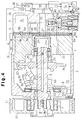
- Fig. 1 is a cross-sectional side view showing a an entire compressor according to a first embodiment of the present invention.
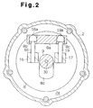
- Fig. 2 is a cross-sectional view taken along line A-A in Fig. 1.
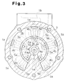
- Fig. 3 is a cross-sectional view taken along line B-B in Fig. 1.
- Fig. 4 is a cross-sectional side view showing the entire compressor with a swash plate at a minimum inclination.
- Fig. 5 is a partially enlarged cross-sectional view showing the swash plate at a maximum inclination.
- Fig. 6 is a partially enlarged cross-sectional view showing the swash plate at a minimum inclination.
- Fig. 7 is a circuit diagram of a refrigerant circulation controlling circuit.
- Fig. 8 is a graph illustrating the refrigerant circulation control.
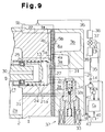
- Fig. 9 is a partial cross-sectional view of a second embodiment.
- Fig. 10 is a circuit diagram of a refrigerant circulation controlling circuit.
- Fig. 11 is a graph illustrating the refrigerant circulation control.
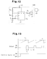
- Fig. 12 is a circuit diagram of a refrigerant circulation controlling circuit according to a third embodiment.
- Fig. 13 is a graph illustrating the refrigerant circulation control.
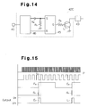
- Fig. 14 is a circuit diagram of a refrigerant circulation controlling circuit according to a fourth embodiment.
- Fig. 15 is a graph illustrating the refrigerant circulation control.
- Fig. 16 is a circuit diagram of a refrigerant circulation controlling circuit according to a fifth embodiment.
- Fig. 17 is a circuit diagram of a refrigerant circulation controlling circuit according to a sixth embodiment.
- Fig. 18 is a partial cross-sectional view showing an embodiment of the program controlling.
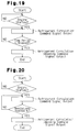
- Fig. 19 is a flow chart illustrating a refrigerant circulation control program.
- Fig. 20 is a flow chart illustrating the refrigerant circulation control program.
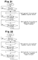
- Fig. 21 is a flow chart illustrating the refrigerant circulation control program.
- Fig. 22 is a flow chart illustrating the refrigerant circulation control program.
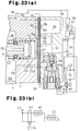
- Fig. 23(a) is a partial cross-sectional view showing a different embodiment.
- Fig. 23(b) is a circuit diagram.
- Fig. 24 is a partial cross-sectional view showing a different embodiment.
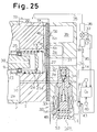
- Fig. 25 is a partial cross-sectional view showing a different embodiment.
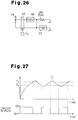
- Fig. 26 is a circuit diagram corresponding to Figs. 24 and 25.
- Fig. 27 is a graph illustrating the refrigerant circulation control.
- Fig. 28 is a cross-sectional side view completely showing a compressor according to another embodiment.
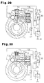
- Fig. 29 is a cross-sectional view showing a rotary compressor according to another embodiment.
- Fig. 30 is a cross-sectional view showing the compressor in a state which refrigerant circulation is impeded.
- Fig. 31 is a cross-sectional side view completely showing a compressor according to another embodiment.
- Fig. 32 is a partial cross-sectional view showing another embodiment.
- Fig. 33 is a flow chart illustrating the refrigerant circulation controlling program.
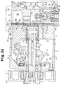
- Fig. 34 is a cross-sectional view completely showing a compressor according to another embodiment.
- Fig. 35 is a partial cross-sectional side view showing the swash plate at a maximum inclination.
- Fig. 36 is a partial cross-sectional side view showing the swash plate at a stop inclination.
- Fig. 37 is a partial cross-sectional view showing another embodiment.
- a front housing 2 is secured to the front end of a cylinder block 1, which serves as part of a housing for the entire compressor.
- a rear housing 3 is secured to the rear end of the block 2 with a valve plate 4, valve forming plates 5A, 5B, and a retainer forming plate 6 provided in between.
- a rotary shaft 9 is rotatably supported to extend between the front housing 2, which serves as part of the housing and has a crank chamber 2a defined therein, and the cylinder block 1. The front end of the rotary shaft 9 protrudes outward from the crank chamber 2a.
- a driven pulley 10 is fixed to the protrusion.
- the driven pulley 10 is operably connected with a vehicle engine by way of a belt 11.
- the driven pulley 10 is supported by an angular contact bearing 7 on the front housing 2.
- a lip seal 12 is provided between the front end of the rotary shaft 9 and the front housing 2.
- the lip seal 12 prevents pressure from escaping the crank chamber 2a.
- a rotary support body 8 is fixed to the rotary shaft 9.
- a swash plate 15 is slidably and tiltably supported with respect to the axial direction of the rotary shaft 9.
- connecting pieces 16, 17 are fixed to the swash plate 15.
- a pair of guide pins 18, 19 are each secured to the connecting pieces 16, 17, respectively.
- Guide spheres 18a, 19a are formed on the distal section of the guide pins 18, 19, respectively.
- a support arm 8a projects from the rotary support body 8.
- a pair of guide holes 8b, 8c are formed in the support arm 8a. The guide spheres 18a, 19a are slidably fitted into the guide holes 8b, 8c, respectively.
- connection between the support arm 8a and the pair of guide pins 18, 19 allows the swash plate 15 to be tiltable with respect to the axial direction of the rotary shaft 9 and enables integral rotation of the swash plate 15 with the rotary shaft 9.
- the tilting of the swash plate 15 is guided by the slide-guide relationship between the support arm 8a and the guide pins 18, 19 and the slide supporting action of the rotary shaft 9.
- a retaining hole 13 is defined in the center of the cylinder block 1 along the axial direction of the rotary shaft 9.
- a tubular shutter 21 is slidably accommodated in the retaining hole 13.
- a suction passage opening spring 24 is arranged between the shutter 21 and the inner surface of the retaining hole 13. The opening spring 24 urges the shutter 21 toward the swash plate 21.
- the rear end of the rotary shaft 9 is inserted into the shutter 21.
- a deep groove bearing 25 is arranged between the rear end of the rotary shaft 9 and the inner surface of the shutter 21.
- the rear end of the rotary shaft 9 is supported by the inner surface of the retaining hole 13 by way of the groove bearing 25 and the shutter 21.
- An outer race 25a of the groove bearing 25 is secured to the inner surface of the shutter 21.
- An inner race 25b of the groove bearing 25 is slidable on the peripheral surface of the rotary shaft 9.
- a stepped portion 9a is defined on the peripheral surface at the rear end of the rotary shaft 9.
- the stepped portion 9a restricts the inner race 25b from moving toward the swash plate 15. That is, the stepped portion 9a restricts the groove bearing 25 from moving toward the swash plate 15. Accordingly, abutment of the groove bearing 25 against the stepped section 9a restricts the shutter 21 from moving toward the swash plate 15.
- a suction passage 26 is defined in the center of the rear housing 3.
- the suction passage 26 is connected to the retaining hole 13.
- a positioning surface 27 is defined about the outlet of the suction passage 26 at the side of the retaining hole 13. The distal end of the shutter 21 is abuttable against the positioning surface 27. Abutment of the distal end of the shutter 21 against the positioning surface 27 restricts the shutter 21 from moving away from the swash plate 15 and disconnects the suction chamber 26 from the retaining hole 13.
- One end of the transmitting cylinder 28 is abuttable against the swash plate 15 and the other end of the transmitting cylinder 28 is abuttable against the inner race 25b of the groove bearing 25 without abutting against the outer race 25a.
- the swash plate 15 moves toward the shutter 21, the swash plate 15 abuts against the transmitting cylinder 28 and presses the transmitting cylinder 28 against the inner race 25b of the groove bearing 25.
- the groove bearing 25 carries the load acting in both radial and thrust directions of the rotary shaft 9.
- the pressing action of the transmitting cylinder 28 urges the shutter 21 toward the positioning surface 27 against the spring force of the opening spring 24. This causes the distal end of the shutter 21 to abut against the positioning surface 27. Accordingly, minimum inclination of the swash plate 15 is restricted by the abutment between the distal end of the shutter 21 and the positioning surface 27.
- a minimum inclination restricting means is constituted by the shutter 21, the groove bearing 25, the positioning surface 27, and the transmitting cylinder 28.
- the minimum inclination of the swash plate 15 is slightly greater than zero degrees. The minimum inclination is obtained when the shutter 21 is arranged at a closing position where it disconnects the suction passage 26 from the retaining hole 13. The shutter 21 moves together with the swash plate 15 between the closing position and an opening position located away from the closing position.
- the maximum inclination of the swash plate 15 is restricted when an inclination restricting projection 8d of the rotary support body 8 abuts against the swash plate 15.
- a single-headed piston 22 is retained in each of the cylinder bores 1a, which are formed in the cylinder block 1 connected to the crank chamber 2a.
- a pair of shoes 23 are fit into the neck of each piston 22.
- the rotational movement of the swash plate 15 is converted to the linear reciprocal movement of the piston 22 by way of the shoes 23. This reciprocally moves the piston 22 in its associated cylinder bore 1a.
- a suction chamber 3a and a discharge chamber 3b are defined in the rear housing 3.
- Suction ports 4a and discharge ports 4b are formed in the valve plate 4.
- Suction valves 5a are formed in the valve forming plate 5A.
- Discharge valves 5b are formed in the valve forming plate 5B.
- the reciprocation of each piston 22 causes the refrigerant gas in the suction chamber 3a to open the suction valve 5a and flow through the suction port 4a into the associated cylinder bore 1a.
- the reciprocation of each piston 22 then causes the refrigerant gas drawn into the associated cylinder bore 1a to open the discharge valve 5b and be discharged through the discharge port 4b into the discharge chamber 3b.
- Each discharge valve 5b abuts against a retainer 6a formed in the retainer forming plate 6.
- a thrust bearing 29 is arranged between the rotary support body 8 and the front housing 2.
- the thrust bearing 29 carries the compression reaction acting on the rotary support body 8 by way of the cylinder bores 1a, the pistons 22, the shoes 23, the swash plate 15, the connecting pieces 16, 17, and the guide pins 18, 19.
- the suction chamber 3a is connected to the retaining hole 13 through an aperture 4c.
- the aperture 4c is disconnected from the suction passage 26.
- the suction passage 26 serves as an entrance through which refrigerant gas flowing into the compressor is drawn.
- the position where the shutter 21 disconnects the suction passage 26 from the suction chamber 3a is located at the downstream side of the suction passage 26.
- a conduit 30 is defined in the rotary shaft 9.
- the conduit 30 connects the crank chamber 2a with the inside of the shutter 21.
- a pressure releasing hole 21a extends through the distal end of the shutter 21.
- the pressure releasing hole 21a connects the retaining hole 13 with the inside of the shutter 21.
- the discharge chamber 3b and the crank chamber 2a are connected to each other through a pressurizing passage 31.
- An electromagnetic valve 32 is provided in the pressurizing passage 31.
- a valve body 34 closes a valve hole 32a.
- the solenoid 33 of the electromagnetic valve 32 By de-energizing the solenoid 33 of the electromagnetic valve 32, the valve body 34 opens the valve hole 32a.
- the electromagnetic valve 32 opens and closes the pressurizing passage 31 which connects the discharge chamber 3b with the crank chamber 2a.
- the suction passage 26, which the refrigerant gas from the suction chamber 3a is drawn through, is connected to an outlet 1b, which the refrigerant gas in the discharge chamber 3b is discharged through, by an external refrigerant circuit 35.
- a condenser 36, an expansion valve 37, and an evaporator 38 are provided in the external refrigerant circuit 35.
- the expansion valve 37 controls the flow rate of the refrigerant in accordance with the fluctuation of the gas pressure at the outlet side of the evaporator 38.
- a temperature sensor 39 is provided in the vicinity of the evaporator 38. The temperature sensor 39 detects the temperature of the evaporator 38. Data of the detected temperature is sent to a control computer C 0 .
- the control computer C 0 controls the energizing and de-energizing of the solenoid 33 of the electromagnetic valve 32 through an amplifying circuit 43.
- the control computer C 0 controls the energizing and de-energizing of the solenoid 33 through the amplifying circuit 43 in accordance with the data of the detected temperature sent from the temperature sensor 39.
- the control computer C 0 commands the de-energizing of the solenoid 33 if the detected temperature becomes equal to or lower than a predetermined temperature.
- a temperature value lower than the predetermined temperature reflects the condition at which frost may form in the evaporator 38.
- the control computer C 0 is connected to the operating switch 40 and a revolution speed detector 41, which detects the engine speed. When the operating switch 40 is turned on, the control computer C 0 de-energizes the solenoid 33 based on certain data of the detected speed fluctuation sent from the speed detector 41. The control computer C 0 also de-energizes the solenoid 33 when the operation switch 40 is turned off.
- a refrigerant circulation controlling circuit 42 is connected to a drive electric source 14 of the engine.
- the engine serves as a drive source that supplies drive source to the compressor.
- the controlling circuit 42 is connected to the amplifying circuit 43.
- Fig. 7 illustrates an example of the circuit constitution of the controlling circuit 42.
- R 1 , R 2 , R 3 represent resistors, K 1 , K 2 represent condensers, Tr represents a switching transistor, IC 1 represents an integrated circuit, F represents a threshold terminal, T represents a trigger terminal, V represents an electric source terminal, and Q represents an output terminal.
- a trigger signal illustrated by a curve E 1 in Fig. 8 is input into the trigger terminal T.
- the integrated circuit IC 1 then sends an ON signal to the transistor Tr from the output terminal Q.
- the amplifying circuit 43 supplies electric power to the electromagnetic valve 32 and energizes the electromagnetic valve 32.
- a signal illustrated by curve E 2 in Fig. 8 is input into the threshold terminal F.
- the integrated circuit IC 1 stops sending signals and the transistor Tr is turned off.
- Time period t 1 which is the length of time required for the signal E 2 to reach the line D, is proportional to the multiplied value of the resistor R 1 and the condenser K 1 .
- the transistor Tr is de-actuated, the supply of electricity from the amplifying circuit 43 to the electromagnetic valve 32 is stopped. This de-energizes the electromagnetic valve 32.
- the electromagnetic valve 32 serves as a forcible swash plate inclination reducing means and also constitutes a refrigerant circulation impeding means together with the shutter 21.
- the solenoid 33 of the electromagnetic valve 32 corresponds to the electric drive circuit of the refrigerant circulation impeding means.
- Figs. 1 and 5 show the solenoid 33 in an energized state.
- the pressurizing passage 31 is closed. Accordingly, high-pressure refrigerant gas is not supplied to the crank chamber 2a from the discharge chamber 3b.
- the refrigerant gas in the crank chamber 2a keeps flowing into the suction chamber 3a through the conduit 30. This causes the pressure in the crank chamber 2a to approach the low pressure, or the suction pressure, in the suction chamber 3a.
- the swash plate 15 is maintained at the maximum inclination and displacement is maximum.
- the temperature of the evaporator 38 approaches the temperature at which frost starts forming.
- the temperature sensor 39 sends the detected temperature data of the evaporator 38 to the control computer C 0 .
- the control computer C 0 de-energizes the solenoid 33.
- De-energizing of the solenoid 33 opens the pressurizing passage 31 and connects the discharge chamber 3b with the crank chamber 2a. Accordingly, the high-pressure refrigerant gas in the discharge chamber 3b is supplied to the crank chamber 2a through the pressurizing passage 31 and increases the pressure in the crank chamber 2a.
- the pressure increase in the crank chamber 2a immediately inclines the swash plate 15 to the minimum inclination side.
- abutment of the distal end of the shutter 21 against the positioning surface 27 causes the swash plate inclination to become minimum. Since the swash plate minimum inclination is not zero degrees, discharge from the cylinder bores 1a to the discharge chamber 3b is performed even when the swash plate inclination is minimum.
- Refrigerant gas discharged into the discharge chamber 3b from the cylinder bores 1a flows into the crank chamber 2a through the pressurizing passage 31.
- the refrigerant gas in the crank chamber 2a flows through the conduit 30 and a pressure releasing hole 21a, which serves as a pressure releasing passage.
- the refrigerant gas in the suction chamber 3a is drawn into the cylinder bores 1a and then discharged into the discharge chamber 3b.
- a circulation passage is defined in the compressor by the discharge chamber 3b, the pressurizing passage 31, the crank chamber 2a, the conduit 30, the pressure releasing hole 21a, the suction chamber 3a, and the cylinder bores 1a.
- the lubricating oil contained in the flowing refrigerant gas lubricates the inside of the compressor.
- the increase in the cooling load is reflected as a temperature increase in the evaporator 38 and the detected temperature of the evaporator 38 exceeds the predetermined temperature.
- the control computer C 0 energizes the solenoid 33 in accordance with the alteration in the detected temperature.
- the energizing of the solenoid 33 closes the pressurizing passage 31 and releases the pressure in the crank chamber 2a through the conduit 30 and the pressure releasing hole 21a to decrease the pressure. This pressure decrease causes the swash plate 15 to incline from the minimum inclination to the maximum inclination.
- the increase in the inclination of the swash plate 15 causes the shutter 21 to follow the inclination of the swash plate 15 due to the spring force of the opening spring 24. This separates the distal end of the shutter 21 from the positioning surface 27. This separation causes the cross-sectional transit area of the refrigerant gas between the suction passage 26 and the suction chamber 3a to gradually increase.
- the gradual increase in the cross-sectional transit area gradually increases the flow rate of the refrigerant gas flowing from the suction passage 26 to the suction chamber 3a, and gradually increases displacement. As a result, the discharge pressure is gradually increased and sudden fluctuation of the compressor torque does not occur.
- the refrigerant circulation controlling circuit 42 stops sending refrigerant circulation impeding command signals during time period t 1 , which is timed from when the engine is started.
- the electromagnetic valve 32 is energized during time period t 1 , which is initiated from when the engine is started, and the pressurizing passage 31 is closed during time period t 1 , initiated from when the engine is started. Accordingly, the refrigerant gas in the discharge chamber 3b is not supplied to the crank chamber 2a through the pressurizing passage 31. This inclines the swash plate 15 from the minimum inclination to the maximum inclination.
- the increase in the inclination causes the refrigerant gas in the external refrigerant circuit 35 to flow into the compressor and lubricate the inside of the compressor with the lubricating oil contained in the refrigerant gas.
- Some of the lubricating oil introduced into the compressor is drawn into the cylinder bores 1a and enters the crank chamber 2a together with the blowby gas that leaks into the crank chamber 2a through the space between each cylinder bore 1a and the peripheral surface of the associated piston 22.
- the control computer C 0 When the operation switch 40 is turned off, the control computer C 0 does not send commands to energize the electromagnetic valve 32. If the electromagnetic valve 32 remains de-energized after starting the engine, refrigerant circulation in the external refrigerant circuit 35 remains impeded. Thus, lubricating oil does not flow into the compressor and the lubricating oil in the compressor may not be sufficient when the engine is stopped. If the engine is started when the lubricating oil in the compressor is insufficient with the operating switch 40 turned off, the lubrication of the inside of the compressor becomes insufficient. Insufficient lubrication may cause seizure of the sliding portions inside the compressor.
- the refrigerant circulation controlling circuit 42 stops sending refrigerant circulation impeding command signals during time period t 1 , which is initiated when the engine is started.
- This allows lubricating oil to be supplied into the compressor from the external refrigerant circuit 35.
- the predetermined time period t 1 is determined by taking into consideration the prevention of frost formation in the evaporator 38.
- a refrigerant circulation controlling circuit 42A is connected to the speed detector 41.
- the refrigerant circulation controlling circuit 42A energizes and de-energizes the electromagnetic valve 32 in accordance with the data of the number of revolutions from the speed detector 41. That is, the refrigerant circulation controlling circuit 42A controls the impeding and allowing of the refrigerant circulation in the external refrigerant circuit 35.
- Fig. 10 illustrates an example of a circuit constitution for a refrigerant circulation controlling circuit.
- 44 represents a dividing circuit
- 45 represents a flip-flop circuit
- R 3 , R 4 represent resistors
- K 3 represents a condenser.
- R represents a reset terminal and S represents a set terminal.
- the resistor R 4 and the condenser K 3 constitute a differentiating circuit.
- the condenser K 3 is connected to the electric source 14.
- the speed detector 41 sends a pulse signal P, shown in Fig. 11, to the dividing circuit 44.
- the dividing circuit 44 then outputs a square wave signal E 3 , shown in Fig. 11, in accordance with the read pulse signal P.
- the differentiating circuit outputs a differentiating signal d 1 when the electric source 14 is turned on.
- the flip-flop circuit 45 sends an ON signal E 4 , which is indicative of curve E 4 and illustrated in Fig. 11, to the transistor Tr and actuates the transistor Tr.
- the differentiating signal is employed to avoid output instability of the ON signal E 4 , which may be caused immediately after the electric source 14 is activated.
- Electric power is supplied to the electromagnetic valve 32 by the amplifying circuit 43 when the transistor Tr is actuated.
- This causes refrigerant circulation in the external refrigerant circuit 35.
- the first onset of the square wave signal E 3 causes the flip-flop circuit 45 to stop transmitting the ON signal E 4 and de-actuates the transistor Tr.
- De-energizing of the transistor Tr causes the amplifying circuit 43 to stop supplying electric power to the electromagnetic valve 32.
- the de-actuated state of the transistor Tr in the refrigerant circulation controlling circuit 42A causes the refrigerant circulation impeding command signal to be output.
- the actuated state of the transistor Tr in the refrigerant circulation controlling circuit 42A stops the output of the refrigerant circulation impeding command signal.
- refrigerant circulation is performed until the number of revolutions reaches a predetermined value N 1 after the engine is started.
- This revolution value N 1 is determined by the dividing ratio of the dividing circuit 44.
- the output of the refrigerant circulation impeding command signal from the refrigerant circulation controlling circuit 42A is stopped until the predetermined revolution value N 1 is reached after starting the engine. Therefore, lubricating oil is also supplied into the compressor from the external refrigerant circuit 35 in this embodiment. Lubricating oil is supplied into the compressor from the external refrigerant circuit 35 each time the engine is started. This solves the problem of lubricating oil becoming insufficient when the engine is operated with the operation switch 40 turned off.
- a third embodiment will hereafter be described with reference to Figs. 12 and 13.
- a refrigerant circulation controlling circuit 42B shown in Fig. 12, is employed instead of the refrigerant circulation controlling circuit 42 described in the first embodiment.
- the remaining constitution is the same as the first embodiment.
- the refrigerant circulation controlling circuit 42B is an example of a circuit for controlling refrigerant circulation based on the predetermined time period.
- R 5 , R 6 represent resistors
- IC 2 represents an integrated circuit
- H represents a discharge terminal.
- ON time period t 2 is proportional to the multiplied value of the resistor R 6 and the condenser K 1 . Afterwards, discharge is performed from the discharge terminal H, the integrated circuit IC 2 stops the output, and the transistor Tr is de-actuated.
- OFF time period t 3 is proportional to the multiplied value of the sum of the resistors R 5 , R 6 and the condenser K 1 .
- the refrigerant circulation impeding command signal is transmitted.
- the predetermined time period t 2 the period of which the transistor Tr is actuated, the output of the refrigerant circulation impeding command signal is stopped.
- periodic intermittent controlling is performed by transmitting the refrigerant circulation impeding command signal from the refrigerant circulation controlling circuit 42B during the predetermined time period t 2 after the signal output is stopped during the predetermined time period t 3 .
- lubricating oil is periodically supplied into the compressor from the external refrigerant circuit 35 when the engine is running. This solves the problem of insufficient lubricating oil when the engine is operated with the operation switch 40 turned off.
- the predetermined time periods t 2 , t 3 are determined by taking into consideration the prevention of frost formation in the evaporator 38.
- a fourth embodiment of the present invention will hereafter be described with reference to Figs. 14 and 15.
- a refrigerant circulation controlling circuit 42C shown in Fig. 14, is employed instead of the refrigerant circulation controlling circuit 42A described in the second embodiment.
- the remaining constitution is the same as the first embodiment.
- Fig. 14 illustrates an example of a circuit constitution for controlling refrigerant circulation based on the revolution data.
- 45 represents the flip-flop circuit which is also employed in the second embodiment
- 46 represents a dividing circuit
- R 7 represents a resistor
- K 5 represents a condenser.
- R represents a reset terminal and S represents a set terminal.
- the resistor R 7 and the condenser K 5 constitute a differentiating circuit.
- the speed detector 41 sends a pulse signal P, shown in Fig. 15, to the dividing circuit 46.
- the dividing circuit 46 then outputs a square wave signal E 5 , E 6 shown in Fig. 15, in accordance with the read pulse signal P.
- the differentiating circuit sends a differentiating signal d 2 to the set terminal S for each onset of the square wave signal E 6 .
- the flip-flop circuit 45 sends an ON signal, which is indicative of curve E 7 and illustrated in Fig. 15, to the transistor Tr and actuates the transistor Tr.
- the actuation of the transistor Tr causes the amplifying circuit 43 to supply electric power to the electromagnetic valve 32 and circulate refrigerant in the external refrigerant circuit 35.
- the flip-flop circuit 45 stops transmitting the ON signal E 7 after the first onset of the square wave signal E 5 subsequent to the output of the differentiating signal d 2 . This de-actuates the transistor Tr.
- De-actuating of the transistor Tr causes the amplifying circuit 43 to stop supplying electric power to the electromagnetic valve 32B. In other words, the transistor Tr is periodically actuated, in which state the output of the refrigerant circulation impeding signal is stopped.
- Revolution value N 3 for determining the period which the ON signal E 7 is output and revolution period N 2 for determining the period which the ON signal E 7 is stopped from being output is determined by the two dividing ratios of the dividing circuit 46.
- periodic intermittent controlling is performed by stopping the output of the refrigerant circulation impeding command signal from the refrigerant circulation controlling circuit 42C when the predetermined engine revolution value N 3 is reached after the revolution value N 2 is reached.
- lubricating oil is periodically supplied into the compressor from the external refrigerant circuit 35 when the engine is operated. This solves the problem of insufficient lubricating oil when the engine is operated with the operation switch 40 turned off.
- the predetermined revolution values N 2 , N 3 are determined by taking into consideration the prevention of frost formation in the evaporator 38.
- a refrigerant circulation controlling circuit 42D which is a combination of the refrigerant circulation controlling circuit 42 described in the first embodiment and the refrigerant circulation controlling circuit 42B described in the third embodiment.
- the refrigerant circulation controlling circuit 42D has the controlling functions of the refrigerant circulation controlling circuit 42 and the controlling functions of the refrigerant circulation controlling circuit 42B.
- a first refrigerant circulation control which stops the output of the refrigerant circulation impeding command signal during the predetermined time period t 1 from when the engine is started
- a periodic second refrigerant circulation control which outputs the refrigerant circulation impeding command signal during the predetermined time period t 3 after stopping the output of the refrigerant circulation impeding command signal during the predetermined time period t 2 when the engine is running, are executed together.
- a refrigerant circulation controlling circuit 42E which is a combination of the refrigerant circulation controlling circuit 42A described in the second embodiment and the refrigerant circulation controlling circuit 42C described in the fourth embodiment.
- the refrigerant circulation controlling circuit 42E has the controlling functions of the refrigerant circulation controlling circuit 42A and the controlling functions of the refrigerant circulation controlling circuit 42C.
- a first refrigerant circulation control which stops the output of the refrigerant circulation impeding command signal during the time period from when the engine is started until when the predetermined revolution value N 1 is reached, is performed together with a periodic second refrigerant circulation control, which outputs the refrigerant circulation impeding command signal until the predetermined revolution value N 2 is reached after stopping the output of the refrigerant circulation impeding command signal until the predetermined revolution value N 3 is reached when the engine is running.
- control computer C 1 program controls the refrigerant circulation when the electric source 14 is activated.
- the flow charts shown in Figs. 19, 20, 21, and 22 are examples of refrigerant circulation control programs.
- the control program shown in Fig. 19 corresponds to the refrigerant circulation control of the first embodiment and the control program shown in Fig. 20 corresponds to the refrigerant circulation program of the second embodiment.
- the control program shown in Fig. 21 corresponds to the refrigerant circulation control of the third embodiment and the control program shown in Fig. 22 corresponds to the refrigerant circulation program of the fourth embodiment.
- the control computer C 1 of the embodiments illustrated in Figs. 19 and 21 has a time measuring function.
- the control computer C 1 controls the output of the refrigerant circulation command signal and the refrigerant circulation impeding command signal based on the measured time.
- the control computer C 1 of the embodiments illustrated in Figs. 20 and 22 controls the output of the refrigerant circulation command signal and the refrigerant circulation impeding command signal based on the revolution data from the speed detector 41.
- the output of the refrigerant circulation command signal corresponds to the stopping of the output of the refrigerant circulation impeding command signal.
- control programs corresponding to the fifth and sixth embodiments may be constructed.
- control programs the selection and alteration of the time periods t 1 , t 2 , t 3 and revolution values N 1 , N 2 , N 3 are simplified.
- FIG. 23(a) and (b) An embodiment according to the present invention shown in Figs. 23(a) and (b) may also be carried out.
- a positive temperature coefficient thermistor 47 is heat connected to the solenoid 33 of the electromagnetic valve 32.
- Fig. 23(b) shows a schematic circuit diagram showing the electrical connection relationship between the electric source 14, the thermistor 47, and the solenoid 33.
- the solenoid 33 and the thermistor 47 are series connected to the electric source 14.
- the solenoid 33 When the electric source 14 is activated, the solenoid 33 is energized to perform refrigerant circulation. As time elapses, the temperature of the solenoid 33 increases. This raises the temperature of the thermistor 47 heat connected to the solenoid 33.
- a flashing switch 52 is constituted by wrapping an insulating material 51 around a heat detecting switch 48, an electric resistor 49, and a thermal conductor 50.
- the flashing switch 52 is located between the electric source 14 and the solenoid 33.
- the heat detecting switch 48 is heat connected to the electric resistor 49 by the thermal conductor 50.
- a metal having high thermal conductivity such as aluminum or copper may be used as the thermal conductor 50.
- Resin having superior thermal insulating performance may be used as the heat insulating material 51.
- the wrapping constitution is advantageous from the aspects of stabilizing movement and durability of the flashing switch 52.
- the detecting switch 48 is retained in a ceramic tube 53, which has high thermal conductivity.
- An electric resistor wire 54 is wound about the peripheral surface of the cylinder 53.
- a detecting switch 52A constituted by wrapping these parts with an insulating material is located between the electric source 14 and the solenoid 33.
- the detecting switch 48 is heat connected to the electric resistor wire 54 by way of the cylinder 53.
- Fig. 26 illustrates a schematic circuit diagram indicating the electrical connection relationship between the electric source 14, the heat detecting switch 48, the electric resistor 49 (or the electric resistor wire 54) and the solenoid 33.
- the solenoid 33 and the heat detecting switch 48 are series connected to the electric source 14.
- the solenoid and the electric resistor 49 (or the electric resistor wire 54) are parallel connected to the heat detecting switch 48.
- Activation of the electric source 14 energizes the solenoid 33 and causes refrigerant circulation.
- the temperature of the electric resistor 49 (or the electric resistor wire 54) increases. This increases the temperature of the heat detecting switch 48 which is heat connected to the electric resistor 49 (or the electric resistor wire 54).
- Fig. 26 illustrates a schematic circuit diagram indicating the electrical connection relationship between the electric source 14, the heat detecting switch 48, the electric resistor 49 (or the electric resistor wire 54) and the solenoid 33.
- the solenoid 33 and the heat detecting switch 48 are series connected to the electric source
- the heat detecting switch 48 is turned off from a state in which it had been turned on when curve E 7 reaches temperature T 1 .
- the heat detecting switch 48 is turned on from a state in which it had been turned off when reaching temperature T 2 .
- the flashing switches 52, 52A repeats ON/OFF actions. This repetitively opens and closes the electromagnetic valve 32. Accordingly, refrigerant circulation is repeated periodically when the engine is operated with the operation switch 40 kept turned off. Additionally, lubrication is ensured in the same manner as in the third and fourth embodiment.
- the present invention may be employed in a clutchless compressor illustrated in Fig. 28 and a rotary type clutchless compressor illustrated in Figs. 29 and 30.
- the pressure in the crank chamber 2a is controlled by a displacement valve 55.
- a released pressure intake port 56 of the displacement control valve 55 is connected to the crank chamber 2a through a passageway 57.
- a suction pressure intake port 58 is connected to the suction passage 26 through a suction pressure intake passageway 59.
- a released pressure port 60 is connected to the suction chamber 3a through a passageway 61.
- a discharge pressure intake port 62 is connected to the discharge chamber 3b through a discharge pressure intake passageway 63.
- the pressure in a suction pressure detection chamber 64, which leads to the suction pressure intake port 62 counteracts an adjustment spring 66 by way of a diaphragm 65.
- the spring force of the adjustment spring 66 is transmitted to the valve body 68 through the diaphragm 65 and a rod 67.
- the valve body 68 which a return spring 69 acts upon, opens and closes a valve hole 70 in accordance with the alteration of the suction pressure in the suction pressure detecting chamber 64.
- the opening and closing causes the released pressure intake port 56 to be connected to and disconnected from the released pressure port 60.
- the suction chamber 3b and the crank chamber 2a are connected to each other through a restriction passage 20.
- the area opened by the valve body 68 is large when the suction pressure is high (the cooling load is large). This increases the flow rate of the refrigerant gas flowing into the suction chamber 3a from the crank chamber 2a. As a result, the pressure in the crank chamber 2a decreases and the swash plate inclination increases. Contrarily, the area opened by the valve body 68 is small when the suction pressure is low (the cooling load is small). This decreases the flow rate of the refrigerant gas flowing into the suction chamber 3a from the crank chamber 2a. Accordingly, the pressure in the crank chamber 2a increases and the swash plate inclination decreases. In other words, displacement is variably controlled continuously.
- the drive pin 76a When the electromagnetic actuator 76 is de-energized, the drive pin 76a is pressed against the side surface of the vane 75 by the urging force of the spring 76b. An engaging hole 75a is formed in the side surface of the vane 75a. The drive pin 76a enters the hole 75a when the electromagnetic actuator 76 is de-energized and causes the vane 75 to be located at a position shown in Fig. 30. This impedes refrigerant circulation. In other words, the electromagnetic actuator 75 constitutes a refrigerant circulation impeding means.
- control computer C 1 program controls the refrigerant circulation when the electric source 14 is activated and ensures lubrication in the compressor in the same manner as the embodiment shown in Fig. 18. It is apparent that a refrigerant circulation control structure described in the first through sixth embodiments and the embodiments shown in Figs. 23 and 24 may be used in the compressor illustrated in Fig. 28 and the compressor illustrated in Figs. 29 and 30.
- a displacement control valve 77 is provided in the rear housing 3.
- the pressure in the crank chamber 2a is controlled by the displacement control valve 77.
- a valve housing 78, which constitutes the displacement control valve 77 includes a discharge pressure intake port 78a, a suction pressure intake port 78b, and a released pressure port 78c.
- the discharge pressure intake port 78b is connected to the suction chamber 3b through a passageway 79.
- the suction passage intake port 78b is connected to the suction passage 26 by a suction pressure intake passageway 80.
- the released pressure port 78c is connected to the crank chamber 2a through a passageway 81.
- the pressure in a suction pressure detection chamber 82 which leads to the suction pressure intake port 78b, counteracts an adjustment spring 84 by way of a diaphragm 83.
- the spring force of the adjustment spring 84 is transmitted to the valve body 86 through the diaphragm 83 and a rod 85.
- the force of a return spring 87 acts on the valve body 86.
- the force applying direction of the return spring 87 with respect to the valve body 86 corresponds to a direction closing the valve hole 78d.
- the valve body 86 closes if the suction pressure becomes high (the cooling load is large). This closes a pressurizing path defined extending through the discharge chamber 3b, the passageway 79, the displacement control valve 77, and the passageway 81.
- the pressure in the crank chamber 2a decreases due to the refrigerant gas in the crank chamber 2a flowing into the suction chamber 3a via the conduit 30 and the pressure releasing hole 21a.
- the suction pressure in the cylinder bores 1a is high, the difference between the pressure in the crank chamber 2a and the suction pressure in the cylinder bores 1a becomes small. This increases the inclination of the swash plate 15.
- the area opened by the valve body 86 becomes large if the suction pressure becomes low (the cooling load is small).
- This increases the flow rate of the refrigerant gas flowing into the crank chamber 2a from the discharge chamber 3b. Accordingly, the pressure in the crank chamber 2a increases.
- the suction pressure in the cylinder bores 1a is low, the difference between the pressure in the crank chamber 2a and the suction pressure in the cylinder bores 1a becomes large.
- the inclination of the swash plate 15 becomes small.
- the area opened by the valve body 86 becomes maximum when the suction pressure is extremely small (there is no cooling load). This increases the pressure in the crank chamber 2a and inclines the swash plate 15 toward the minimum inclination. Furthermore, the pressurizing passage 31 is opened when the solenoid 33 is de-energized. When the solenoid 33 is energized, the pressurizing passage 31 closes.
- the swash plate inclination is variably controlled continuously.
- the control computer C 1 executes any one of the refrigerant circulation control programs illustrated in the flowcharts in Figs. 19 through 22 in accordance with the revolution data from the speed detector 41.
- the de-energizing signal sent to the electromagnetic valve 32 from the control computer C 1 corresponds to a refrigerant circulation impeding command signal.
- the control computer C 1 program controls the refrigerant circulation when the electric source 14 is activated and ensures lubrication in the compressor.
- the swash plate inclination controlling responsiveness is high when the displacement is controlled by controlling the flow rate of the refrigerant gas supplied to the crank chamber 2a from the discharge chamber 3b in comparison to when the displacement is controlled by controlling the flow rate of the refrigerant gas released into the suction chamber 3a from the crank chamber 2a as shown in Fig. 28. This is because the refrigerant gas supplied to the crank chamber 2a is high pressure discharged refrigerant gas.
- the crank chamber 2a and the suction chamber 3a are connected by a pressure releasing passageway 88.
- An electromagnetic valve 89 is provided in the pressure releasing passageway 88.
- a solenoid 90 of the electromagnetic valve 89 When a solenoid 90 of the electromagnetic valve 89 is energized, a valve body 91 opens a valve hole 89a.
- the solenoid 90 When the solenoid 90 is de-energized, the valve body 91 closes the valve hole 89a.
- the discharge chamber 3b and the crank chamber 2a are connected to each other by a pressurizing passage 92.
- the refrigerant gas in the discharge chamber 3b is constantly supplied to the crank chamber 2a through the pressurizing passage 92.
- the control computer C 1 de-energizes the solenoid 90.
- the solenoid 90 is de-energized, the pressure releasing passageway 88 is closed and the suction chamber 3a becomes disconnected from the crank chamber 2a. Accordingly, the refrigerant gas stops flowing through the pressure releasing passageway 88 from the crank chamber 2a to the suction chamber 3a and increases the pressure in the crank chamber 2a.
- the pressure increase in the crank chamber 2a causes the swash plate 15 to incline toward the minimum inclination.
- the control program energizes the solenoid 90.
- the control computer C 1 executes a refrigerant circulation control program illustrated in Fig. 33 in accordance with the revolution data from the speed detector 41.
- the control computer C 1 energizes the electromagnetic valve 89. This opens the pressure releasing passageway 88 and inclines the swash plate 15 toward the minimum inclination.
- the energizing of the electromagnetic valve 89 continues during time period t 4 which is longer than the time period required for the swash plate 15 to incline to the minimum inclination.
- the computer C 1 then de-energizes the electromagnetic valve 89 and closes the pressure releasing passageway 88.
- the control computer C 1 When the engine is started and time t 1 elapses after the revolutions per unit time detected by the speed detector 41 exceed the predetermined revolution value M, the control computer C 1 enters a mode that allows the energizing of the electromagnetic valve 89. During the period in which time period t 1 has not yet elapsed, the control computer C 1 does not energize the electromagnetic valve 89 even when the temperature detected by the temperature sensor 39 exceeds the predetermined temperature.
- control computer C 1 program controls the refrigerant circulation in accordance with the data of the revolution speed sent from the speed detector 41. This ensures lubrication inside the compressor.
- Figs. 34 to 36 An embodiment described in Figs. 34 to 36 will hereafter be described. Parts that are identical to parts illustrated in Fig. 1 are denoted with the same reference numerals and will not be described in detail.
- the positioning surface 27 is defined on the valve forming plate 5A and the shutter 21 abuts against the valve forming plate 5A.
- a compression spring 94 is arranged between the rotary support body 8 and the swash plate 15. The compression spring 94 urges the swash plate 15 toward a direction which its inclination is minimized.
- a belleville spring 93 is accommodated in the retaining hole 13.
- the shutter 21 abuts against the belleville spring 93 before abutting against the positioning surface 27.
- the shutter 21 causes elastic deformation and flattens the belleville spring 93 to close the suction passage 26.
- the difference between the pressure in the crank chamber 2a and the suction pressure together with the spring force of the compression spring 94 causes the shutter 21 to flatten and deform the belleville spring 93 in an elastic manner to close the suction passage 26.
- the swash plate 15 starts rotation at the stop inclination. Accordingly, refrigerant circulates in the external refrigerant circuit 35 and ensures lubrication in the compressor.
- the belleville spring 93 guarantees immediate refrigerant circulation in the external refrigerant circuit 35 regardless of the swash plate 15 increasing its inclination from the minimum inclination at an extremely slow rate.
- the positioning surface 27 is defined on the valve forming plate 5A, which has the property of a spring.
- a leaf spring portion 5c is defined at the section of the valve forming plate 5A exposed to the inside of the retaining hole 13.
- the shutter 21 causes elastic deformation and flattens the leaf spring 5c to close the suction passage 26.
- the leaf spring portion 5c substitutes the belleville spring 93 of Fig. 34 and causes the shutter 21 to be separated from the positioning surface 27 when the engine is not running. This inclines the swash plate 15 to the stop inclination. Accordingly, lubrication in the compressor is ensured.
- Figs. 34 and 37 perform energizing and de-energizing control in a manner such as shown in the flowcharts of Figs. 19 to 22.
- lubrication in the compressor may be ensured without such energizing and de-energizing control.
- the swash plate 15 starts rotation at the stop inclination and refrigerant circulates in the external refrigerant circuit 35 even if the electromagnetic valve 32 is not energized.
- a difference in the pressures in the discharge chamber 3b, the crank chamber 2a, and the suction chamber 3a takes place.
- the present invention may be applied to a clutchless compressor, such as the compressor described in Japanese Unexamined Patent Publication 3-37378, which is provided with a refrigerant circulation impeding means that impedes the flow of refrigerant gas from the external refrigerant circuit to the suction chamber by using an electromagnetic valve.
- a clutchless compressor such as the compressor described in Japanese Unexamined Patent Publication 3-37378, which is provided with a refrigerant circulation impeding means that impedes the flow of refrigerant gas from the external refrigerant circuit to the suction chamber by using an electromagnetic valve.
- the suction pressure zone includes the interior of the retaining hole 13, which is defined by the shutter 21 in the crank chamber 2a, and the aperture 4c.
- the discharge pressure zone includes the inside of the outlet 1b, and the external refrigerant circuit at the section between the outlet 1b and the condenser 36.
- the refrigerant circulation in the external refrigerant circuit is immediately started when the swash plate starts rotation regardless of the pressurizing passage being closed.
- the output of a refrigerant circulation impeding command signal from a refrigerant circulation controlling means is stopped during a predetermined time period initiated when a drive source, which supplies drive power to the clutchless compressor, is activated.
- a drive source which supplies drive power to the clutchless compressor
- This draws the refrigerant gas, which contains the lubricating oil, into the compressor from the external refrigerant circuit after the drive source is activated.
- the output of the refrigerant circulation impeding command signal from the refrigerant circulation controlling means is periodically stopped when the drive source is in an activated state. This periodically draws the refrigerant gas, which contains the lubricating oil, into the compressor from the external refrigerant circuit. As a result, the advantageous effect of ensuring sufficient lubrication in the compressor is obtained.
- the output of the refrigerant circulation impeding command signal from the refrigerant circulation controlling means is stopped for a predetermined time period initiated when the drive source is activated.
- the output of the refrigerant circulation impeding command signal from the refrigerant circulation controlling means is also periodically stopped when the drive source is in an activated state. This draws the refrigerant gas containing the lubricating oil into the compressor from the external refrigerant circuit immediately after the drive source is activated. It also periodically draws the lubricating oil into the compressor from the external refrigerant circuit when the drive source is in an activated state.
- a refrigerant circulation controlling means is constituted by electrically connecting a positive temperature coefficient thermistor to an electric drive circuit of the refrigerant circulation impeding means, series connecting the electric drive circuit and the positive temperature coefficient thermistor with respect to a drive electric source of the drive source, and heat connecting the positive coefficient thermistor to an electric resistor.
- a refrigerant circulation controlling means is constituted by electrically connecting a heat detecting switch to an electric drive circuit of the refrigerant circulation impeding means, series connecting the electric drive circuit and the heat detecting switch with respect to a drive electric source of the drive source, and parallel connecting the electric drive circuit and a resistor with respect to the heat detecting switch.
- the output of the refrigerant circulation impeding command signal periodically stopped either during a certain time period or when the drive source is in an activated state.
- a forcible swash plate inclination reducing means closes a pressurizing passage when the output of the refrigerant circulation impeding command signal is stopped. This either draws the refrigerant gas containing the lubricating oil into the compressor from the external refrigerant circulation immediately after the drive source is activated or periodically draws lubricating oil into the compressor from the external refrigerant circuit when the drive source is in an activated state.
Landscapes
- Engineering & Computer Science (AREA)
- Mechanical Engineering (AREA)
- General Engineering & Computer Science (AREA)
- Compressors, Vaccum Pumps And Other Relevant Systems (AREA)
- Control Of Positive-Displacement Pumps (AREA)
- Hydraulic Clutches, Magnetic Clutches, Fluid Clutches, And Fluid Joints (AREA)
Applications Claiming Priority (4)
| Application Number | Priority Date | Filing Date | Title |
|---|---|---|---|
| JP82741/95 | 1995-04-07 | ||
| JP8274195 | 1995-04-07 | ||
| JP07082741A JP3094836B2 (ja) | 1994-04-12 | 1995-04-07 | クラッチレス圧縮機における潤滑方法及び潤滑制御装置 |
| PCT/JP1995/002354 WO1996031699A1 (fr) | 1995-04-07 | 1995-11-17 | Procede de lubrification dans un compresseur sans embrayage et commande de lubrification |
Publications (3)
| Publication Number | Publication Date |
|---|---|
| EP0764782A1 true EP0764782A1 (fr) | 1997-03-26 |
| EP0764782A4 EP0764782A4 (fr) | 1997-09-24 |
| EP0764782B1 EP0764782B1 (fr) | 2001-03-07 |
Family
ID=13782850
Family Applications (1)
| Application Number | Title | Priority Date | Filing Date |
|---|---|---|---|
| EP95938028A Expired - Lifetime EP0764782B1 (fr) | 1995-04-07 | 1995-11-17 | Procede de lubrification dans un compresseur sans embrayage et commande de lubrification |
Country Status (7)
| Country | Link |
|---|---|
| US (1) | US5807076A (fr) |
| EP (1) | EP0764782B1 (fr) |
| KR (1) | KR100203978B1 (fr) |
| CN (1) | CN1083056C (fr) |
| CA (1) | CA2184488C (fr) |
| DE (1) | DE69520272T2 (fr) |
| WO (1) | WO1996031699A1 (fr) |
Cited By (3)
| Publication number | Priority date | Publication date | Assignee | Title |
|---|---|---|---|---|
| EP1006011A2 (fr) * | 1998-11-24 | 2000-06-07 | Kabushiki Kaisha Toyoda Jidoshokki Seisakusho | Conditionnement d'air d'un véhicule et procédé de réglage dudit conditionnement d'air |
| US6152845A (en) * | 1997-12-11 | 2000-11-28 | Kabushiki Kaisha Toyoda Jidoshokki Seisakusho | Power transmission apparatus |
| EP1081378A2 (fr) * | 1999-08-31 | 2001-03-07 | Kabushiki Kaisha Toyoda Jidoshokki Seisakusho | Soupape de régulation d'un compresseur à capacité variable |
Families Citing this family (15)
| Publication number | Priority date | Publication date | Assignee | Title |
|---|---|---|---|---|
| JPH102284A (ja) * | 1996-06-17 | 1998-01-06 | Toyota Autom Loom Works Ltd | 可変容量圧縮機及びその制御方法 |
| JP3062436B2 (ja) * | 1996-07-09 | 2000-07-10 | 株式会社ユニクラ | 斜板式圧縮機 |
| JP3585148B2 (ja) * | 1996-12-16 | 2004-11-04 | 株式会社豊田自動織機 | 可変容量圧縮機用制御弁 |
| FR2761414B1 (fr) * | 1997-02-25 | 2002-09-06 | Linde Ag | Systeme de reglage pour une unite hydrostatique volumetrique |
| JPH11159449A (ja) * | 1997-11-27 | 1999-06-15 | Toyota Autom Loom Works Ltd | 可変容量型圧縮機 |
| JP3820766B2 (ja) * | 1998-03-06 | 2006-09-13 | 株式会社豊田自動織機 | 圧縮機 |
| JP3984724B2 (ja) * | 1998-09-10 | 2007-10-03 | 株式会社豊田自動織機 | 容量可変型斜板式圧縮機の制御弁及び斜板式圧縮機 |
| JP2000329062A (ja) * | 1999-05-19 | 2000-11-28 | Toyota Autom Loom Works Ltd | 可変容量型圧縮機における容量制御構造 |
| JP2002021720A (ja) * | 2000-07-06 | 2002-01-23 | Toyota Industries Corp | 容量可変型圧縮機の制御弁 |
| JP4050899B2 (ja) * | 2001-12-21 | 2008-02-20 | ユニクラ インターナショナル リミテッド | 斜板式圧縮機およびそのハウジング |
| JP2006088979A (ja) * | 2004-09-27 | 2006-04-06 | Denso Corp | 車両用空調装置 |
| EP2372153B1 (fr) * | 2010-03-17 | 2020-07-29 | Valeo Compressor Europe, s.r.o. | Geschwindigkeitssensor |
| CN107489708B (zh) * | 2017-05-23 | 2019-11-22 | 宝沃汽车(中国)有限公司 | 一种离合器及具有该离合器的车辆 |
| US11718148B2 (en) | 2018-01-23 | 2023-08-08 | Ford Global Technologies Llc | Electrified vehicle refrigerant system |
| CN114776565B (zh) * | 2022-05-18 | 2023-09-05 | 龙口利佳电气有限公司 | 一种止推轴承型式隔膜增压泵 |
Citations (2)
| Publication number | Priority date | Publication date | Assignee | Title |
|---|---|---|---|---|
| US3844684A (en) * | 1972-08-07 | 1974-10-29 | Hitachi Ltd | Preliminary compressor lubricating device |
| EP0628722A1 (fr) * | 1993-06-08 | 1994-12-14 | Kabushiki Kaisha Toyoda Jidoshokki Seisakusho | Compresseur à plateau oblique |
Family Cites Families (8)
| Publication number | Priority date | Publication date | Assignee | Title |
|---|---|---|---|---|
| JPS62119483U (fr) * | 1986-01-21 | 1987-07-29 | ||
| JPS62191673A (ja) * | 1986-02-17 | 1987-08-22 | Diesel Kiki Co Ltd | 可変容量型揺動板式圧縮機 |
| JPH0717151B2 (ja) * | 1987-07-04 | 1995-03-01 | 株式会社豊田自動織機製作所 | 可変容量コンプレッサの運転制御方法 |
| JPS6466477A (en) * | 1987-09-05 | 1989-03-13 | Toyoda Automatic Loom Works | Method of controlling capacity of capacity-variable compressor for air conditioner |
| US5173032A (en) * | 1989-06-30 | 1992-12-22 | Matsushita Electric Industrial Co., Ltd. | Non-clutch compressor |
| JPH0337378A (ja) * | 1989-06-30 | 1991-02-18 | Matsushita Electric Ind Co Ltd | クラッチレスコンプレッサ |
| JP3089901B2 (ja) * | 1993-07-20 | 2000-09-18 | 株式会社豊田自動織機製作所 | クラッチレス圧縮機における動力伝達構造 |
| US5603610A (en) * | 1993-12-27 | 1997-02-18 | Kabushiki Kaisha Toyoda Jidoshokki Seisakusho | Clutchless piston type variable displacement compressor |
-
1995
- 1995-11-17 EP EP95938028A patent/EP0764782B1/fr not_active Expired - Lifetime
- 1995-11-17 KR KR1019960704760A patent/KR100203978B1/ko not_active IP Right Cessation
- 1995-11-17 CA CA002184488A patent/CA2184488C/fr not_active Expired - Fee Related
- 1995-11-17 CN CN95191908A patent/CN1083056C/zh not_active Expired - Fee Related
- 1995-11-17 WO PCT/JP1995/002354 patent/WO1996031699A1/fr active IP Right Grant
- 1995-11-17 DE DE69520272T patent/DE69520272T2/de not_active Expired - Fee Related
- 1995-11-17 US US08/702,606 patent/US5807076A/en not_active Expired - Fee Related
Patent Citations (2)
| Publication number | Priority date | Publication date | Assignee | Title |
|---|---|---|---|---|
| US3844684A (en) * | 1972-08-07 | 1974-10-29 | Hitachi Ltd | Preliminary compressor lubricating device |
| EP0628722A1 (fr) * | 1993-06-08 | 1994-12-14 | Kabushiki Kaisha Toyoda Jidoshokki Seisakusho | Compresseur à plateau oblique |
Non-Patent Citations (1)
| Title |
|---|
| See also references of WO9631699A1 * |
Cited By (5)
| Publication number | Priority date | Publication date | Assignee | Title |
|---|---|---|---|---|
| US6152845A (en) * | 1997-12-11 | 2000-11-28 | Kabushiki Kaisha Toyoda Jidoshokki Seisakusho | Power transmission apparatus |
| EP1006011A2 (fr) * | 1998-11-24 | 2000-06-07 | Kabushiki Kaisha Toyoda Jidoshokki Seisakusho | Conditionnement d'air d'un véhicule et procédé de réglage dudit conditionnement d'air |
| EP1006011A3 (fr) * | 1998-11-24 | 2001-10-10 | Kabushiki Kaisha Toyoda Jidoshokki Seisakusho | Conditionnement d'air d'un véhicule et procédé de réglage dudit conditionnement d'air |
| EP1081378A2 (fr) * | 1999-08-31 | 2001-03-07 | Kabushiki Kaisha Toyoda Jidoshokki Seisakusho | Soupape de régulation d'un compresseur à capacité variable |
| EP1081378A3 (fr) * | 1999-08-31 | 2002-08-14 | Kabushiki Kaisha Toyota Jidoshokki | Soupape de régulation d'un compresseur à capacité variable |
Also Published As
| Publication number | Publication date |
|---|---|
| KR100203978B1 (ko) | 1999-06-15 |
| CA2184488A1 (fr) | 1996-10-08 |
| CN1143404A (zh) | 1997-02-19 |
| US5807076A (en) | 1998-09-15 |
| DE69520272T2 (de) | 2001-08-09 |
| CN1083056C (zh) | 2002-04-17 |
| DE69520272D1 (de) | 2001-04-12 |
| EP0764782A4 (fr) | 1997-09-24 |
| EP0764782B1 (fr) | 2001-03-07 |
| CA2184488C (fr) | 2000-07-04 |
| WO1996031699A1 (fr) | 1996-10-10 |
Similar Documents
| Publication | Publication Date | Title |
|---|---|---|
| EP0764782B1 (fr) | Procede de lubrification dans un compresseur sans embrayage et commande de lubrification | |
| US5529461A (en) | Piston type variable displacement compressor | |
| US5797730A (en) | Swash plate type compressor | |
| CA2178875C (fr) | Dispositif de reglage de compresseur a cylindree variable sans embrayage | |
| US6453685B2 (en) | Control apparatus and control method for variable displacement compressor | |
| EP1081378A2 (fr) | Soupape de régulation d'un compresseur à capacité variable | |
| EP0848164A2 (fr) | Soupape de contrÔle pour compresseur à capacité variable | |
| US5603610A (en) | Clutchless piston type variable displacement compressor | |
| US6389824B2 (en) | Controller for variable displacement compressor | |
| JP3255008B2 (ja) | 可変容量圧縮機及びその制御方法 | |
| US5616008A (en) | Variable displacement compressor | |
| EP0635640A1 (fr) | Structure de palier utilisée dans un compresseur | |
| EP0824191B1 (fr) | Compresseur à déplacement variable | |
| JP2000161234A (ja) | 容量可変型圧縮機及び容量可変型圧縮機の容量制御弁 | |
| US6672844B2 (en) | Apparatus and method for controlling variable displacement compressor | |
| US6848262B2 (en) | Compressor device and control method for the same | |
| US6572341B2 (en) | Variable displacement type compressor with suction control valve | |
| US5741122A (en) | Variable displacement compressor having a spool with a coating layer | |
| US6694764B1 (en) | Air conditioning system with electric compressor | |
| US5713725A (en) | Clutchless piston type variable displacement compressor | |
| KR0146771B1 (ko) | 클러치없는 단방향 피스톤식 가변용량 압축기 | |
| US20020144512A1 (en) | Apparatus and method for controlling variable displacement compressor | |
| JP3812247B2 (ja) | 可変容量型圧縮機 | |
| KR20220142579A (ko) | 용량 가변형 사판식 압축기 | |
| EP1167763A2 (fr) | Compresseur à plateau en biais à capacité variable |
Legal Events
| Date | Code | Title | Description |
|---|---|---|---|
| PUAI | Public reference made under article 153(3) epc to a published international application that has entered the european phase |
Free format text: ORIGINAL CODE: 0009012 |
|
| 17P | Request for examination filed |
Effective date: 19960830 |
|
| AK | Designated contracting states |
Kind code of ref document: A1 Designated state(s): DE FR GB IT |
|
| RHK1 | Main classification (correction) |
Ipc: F04B 39/02 |
|
| A4 | Supplementary search report drawn up and despatched | ||
| AK | Designated contracting states |
Kind code of ref document: A4 Designated state(s): DE FR GB IT |
|
| 17Q | First examination report despatched |
Effective date: 19980116 |
|
| GRAG | Despatch of communication of intention to grant |
Free format text: ORIGINAL CODE: EPIDOS AGRA |
|
| GRAG | Despatch of communication of intention to grant |
Free format text: ORIGINAL CODE: EPIDOS AGRA |
|
| GRAH | Despatch of communication of intention to grant a patent |
Free format text: ORIGINAL CODE: EPIDOS IGRA |
|
| GRAH | Despatch of communication of intention to grant a patent |
Free format text: ORIGINAL CODE: EPIDOS IGRA |
|
| GRAA | (expected) grant |
Free format text: ORIGINAL CODE: 0009210 |
|
| AK | Designated contracting states |
Kind code of ref document: B1 Designated state(s): DE FR GB IT |
|
| ITF | It: translation for a ep patent filed |
Owner name: JACOBACCI & PERANI S.P.A. |
|
| REF | Corresponds to: |
Ref document number: 69520272 Country of ref document: DE Date of ref document: 20010412 |
|
| ET | Fr: translation filed | ||
| REG | Reference to a national code |
Ref country code: GB Ref legal event code: IF02 |
|
| PLBE | No opposition filed within time limit |
Free format text: ORIGINAL CODE: 0009261 |
|
| STAA | Information on the status of an ep patent application or granted ep patent |
Free format text: STATUS: NO OPPOSITION FILED WITHIN TIME LIMIT |
|
| 26N | No opposition filed | ||
| PGFP | Annual fee paid to national office [announced via postgrant information from national office to epo] |
Ref country code: FR Payment date: 20031110 Year of fee payment: 9 |
|
| PGFP | Annual fee paid to national office [announced via postgrant information from national office to epo] |
Ref country code: GB Payment date: 20031112 Year of fee payment: 9 |
|
| PGFP | Annual fee paid to national office [announced via postgrant information from national office to epo] |
Ref country code: DE Payment date: 20031127 Year of fee payment: 9 |
|
| PG25 | Lapsed in a contracting state [announced via postgrant information from national office to epo] |
Ref country code: GB Free format text: LAPSE BECAUSE OF NON-PAYMENT OF DUE FEES Effective date: 20041117 |
|
| PG25 | Lapsed in a contracting state [announced via postgrant information from national office to epo] |
Ref country code: DE Free format text: LAPSE BECAUSE OF NON-PAYMENT OF DUE FEES Effective date: 20050601 |
|
| GBPC | Gb: european patent ceased through non-payment of renewal fee |
Effective date: 20041117 |
|
| PG25 | Lapsed in a contracting state [announced via postgrant information from national office to epo] |
Ref country code: FR Free format text: LAPSE BECAUSE OF NON-PAYMENT OF DUE FEES Effective date: 20050729 |
|
| REG | Reference to a national code |
Ref country code: FR Ref legal event code: ST |
|
| PG25 | Lapsed in a contracting state [announced via postgrant information from national office to epo] |
Ref country code: IT Free format text: LAPSE BECAUSE OF NON-PAYMENT OF DUE FEES Effective date: 20051117 |