EP0764751B1 - Elektromotorischer Stellantrieb für Kraftfahrzeuge - Google Patents
Elektromotorischer Stellantrieb für Kraftfahrzeuge Download PDFInfo
- Publication number
- EP0764751B1 EP0764751B1 EP96114670A EP96114670A EP0764751B1 EP 0764751 B1 EP0764751 B1 EP 0764751B1 EP 96114670 A EP96114670 A EP 96114670A EP 96114670 A EP96114670 A EP 96114670A EP 0764751 B1 EP0764751 B1 EP 0764751B1
- Authority
- EP
- European Patent Office
- Prior art keywords
- shaft
- thread
- housing
- actuator according
- push
- Prior art date
- Legal status (The legal status is an assumption and is not a legal conclusion. Google has not performed a legal analysis and makes no representation as to the accuracy of the status listed.)
- Expired - Lifetime
Links
- 230000013011 mating Effects 0.000 claims description 6
- 238000010276 construction Methods 0.000 claims 2
- 238000004519 manufacturing process Methods 0.000 description 4
- 238000013461 design Methods 0.000 description 3
- 230000005540 biological transmission Effects 0.000 description 2
- 230000008878 coupling Effects 0.000 description 2
- 238000010168 coupling process Methods 0.000 description 2
- 238000005859 coupling reaction Methods 0.000 description 2
- 239000000463 material Substances 0.000 description 2
- 238000005452 bending Methods 0.000 description 1
- 230000002146 bilateral effect Effects 0.000 description 1
- 238000011161 development Methods 0.000 description 1
- 230000018109 developmental process Effects 0.000 description 1
- 238000006073 displacement reaction Methods 0.000 description 1
- 238000005553 drilling Methods 0.000 description 1
- 230000000694 effects Effects 0.000 description 1
- 238000012360 testing method Methods 0.000 description 1
- 238000012549 training Methods 0.000 description 1
- 238000012546 transfer Methods 0.000 description 1
Images

Classifications
-
- E—FIXED CONSTRUCTIONS
- E05—LOCKS; KEYS; WINDOW OR DOOR FITTINGS; SAFES
- E05B—LOCKS; ACCESSORIES THEREFOR; HANDCUFFS
- E05B81/00—Power-actuated vehicle locks
- E05B81/24—Power-actuated vehicle locks characterised by constructional features of the actuator or the power transmission
- E05B81/25—Actuators mounted separately from the lock and controlling the lock functions through mechanical connections
-
- F—MECHANICAL ENGINEERING; LIGHTING; HEATING; WEAPONS; BLASTING
- F16—ENGINEERING ELEMENTS AND UNITS; GENERAL MEASURES FOR PRODUCING AND MAINTAINING EFFECTIVE FUNCTIONING OF MACHINES OR INSTALLATIONS; THERMAL INSULATION IN GENERAL
- F16H—GEARING
- F16H25/00—Gearings comprising primarily only cams, cam-followers and screw-and-nut mechanisms
- F16H25/18—Gearings comprising primarily only cams, cam-followers and screw-and-nut mechanisms for conveying or interconverting oscillating or reciprocating motions
- F16H25/20—Screw mechanisms
- F16H25/2015—Means specially adapted for stopping actuators in the end position; Position sensing means
-
- F—MECHANICAL ENGINEERING; LIGHTING; HEATING; WEAPONS; BLASTING
- F16—ENGINEERING ELEMENTS AND UNITS; GENERAL MEASURES FOR PRODUCING AND MAINTAINING EFFECTIVE FUNCTIONING OF MACHINES OR INSTALLATIONS; THERMAL INSULATION IN GENERAL
- F16H—GEARING
- F16H25/00—Gearings comprising primarily only cams, cam-followers and screw-and-nut mechanisms
- F16H25/18—Gearings comprising primarily only cams, cam-followers and screw-and-nut mechanisms for conveying or interconverting oscillating or reciprocating motions
- F16H25/20—Screw mechanisms
- F16H2025/2062—Arrangements for driving the actuator
- F16H2025/2081—Parallel arrangement of drive motor to screw axis
Definitions
- the invention relates to an electromotive actuator for motor vehicles, especially for central locking systems, with a housing, with a Electric motor that drives a threaded shaft and a push rod that works with a counter thread engages in the thread of the shaft, and that in the housing is guided longitudinally.
- Such electromotive actuators are from EP 0 287 860 A2, EP 0 358 346 B1 and DE 39 13 995 C2 are known.
- the actuators there point in Area of the gear arrangement and in the area of power transmission from the shaft on the push rod, especially when the housing is retracted into the Push rod on a rigid power transmission.
- a slip clutch is required, which is the excess torque of the electric motor when the push rod stops on the end stops.
- slip clutch is manufacturing and costly. Also are such slip clutches are subject to considerable wear and tear what especially with intensive use of the actuator also to failures of the Actuators can lead.
- the invention has for its object an electromotive actuator for To create motor vehicles that is easy and inexpensive to manufacture, that only is subject to low wear and the one compared to the previous has increased operational reliability.
- the length of the Counter thread of the push rod at least equal to the stroke of the push rod compared to the housing is that the length of the thread of the shaft is less than the length of the counter thread of the push rod and that the thread of the shaft the output side of the shaft is arranged so that there is a thread-free Results in the range of waves that the movement of the push rod on Housing stops allow torsion of the shaft.
- the length of the shaft thread is at least as large as the stroke of the push rod, whereas the length of the counter thread compared to the length of the shaft thread is much smaller.
- This Aspect ratios are reversed in the present invention that between the drive side of the shaft by the torque of the electric motor is applied, and the output side of the shaft on which the shaft thread is arranged, a shaft area without thread remains free during movement the push rod on one of the two end stops a torsion of the shaft enables.
- This wave torsion made possible according to the invention catches the Excess torque that the electric motor when moving the push rods on one of the end stops creates and destroys it by the torsion of the shaft, causing damage to the actuator in this operating state without further measures are prevented.
- the length of the thread of the shaft is approximately one Third of the length of the thread of the push rod.
- the length of the shaft thread is sufficient to the transfer the required forces to the push rod.
- This aspect ratio is a sufficiently large shaft area that has no thread has and can be subjected to torsion as a torsion clutch.
- the thread of the shaft can be 3 to 5, preferably 4 Have threads that are also used to transmit the required forces suffice, as tests have shown.
- Threads also only encompass a partial circumference of the shaft, if necessary also the bending of the shaft perpendicular to the shaft axis during its torsion enable.
- a gear arrangement is often provided between the electric motor and the shaft, whose motor pinion drives a gearwheel that is non-rotatably connected to the shaft.
- the thread can be particularly advantageous on that facing away from the gear Side of the shaft to be arranged to the greatest possible length of the twistable To ensure the waveband.
- the actuator according to the invention is shown in In this context, the use of a known Spoke gear, which is also in the movement of the push rod on a their stops a torsion of the hub of the spoke gear relative to the Sprocket allows. Trials have shown that sharing a spoke gear with the twistable shaft a rotation of the Gear rim against the shaft thread of up to 360 ° when using Permits plastic materials without the arrangement being permanently damaged would.
- the spoke gear can be particularly advantageous be designed such that the spokes of the gear have teeth that engages in a torsion spring of a torsion spring cassette.
- the torsion spring serves thereby resetting the electromotive actuator to its basic position with the push rod retracted, provided the electric motor is de-energized.
- the order The torsion spring in a torsion spring cassette enables easy assembly the arrangement consisting of shaft and torsion spring in the housing of electromotive actuator.
- the thread of the Shaft is an external thread and if the counter thread of the push rod is on Is internal thread, which is arranged in a bore of the push rod.
- the push rod can be relatively large in cross section be formed.
- the push rod is the only part that comes out of the housing of the electromotive actuator and in this respect special can be exposed to mechanical loads. This mechanical Loads can be easily absorbed by a push rod with a large cross-section become.
- the push rod can particularly advantageously have stop elements that with Interact housing stops. These separate stop elements can with appropriate design, can be moved elastically relative to the push rod be so that a hard impact of the push rod on the housing and thus Another possibility of damaging the housing is also avoided becomes.
- the stop elements can be particularly advantageous be box-shaped in the sense of a four-bar hinge with film hinges. This design of the stop elements is particularly when the Push rod made of plastic material can be easily realized, whereby through the box-shaped training the desired elastic displacement of the Stop elements against the push rod is guaranteed.
- the shaft can unite on the side facing away from the thread Have shaft flange that cooperates with an end face of the push rod.
- This arrangement represents a further stop, which then becomes effective, if the stop elements are already in contact with the housing stops and are elastically displaced relative to the push rod.
- This further Measure is excessive torsion, which leads to permanent deformation of the Can lead wave avoided and the further torsion if necessary provided impeller or the other parts of the gear arrangement left.
- Actuator can be the electrical plug contacts that make the electrical connection between the electric motor and the rest of the vehicle electrical system produce, pressed into the housing wall and at the same time in the electric motor electrical connection.
- the required longitudinally displaceable guidance of the push rod in the housing of the electromotive actuator can be special through a labyrinth seal advantageously be made in one piece with the housing or the individual Housing parts is formed.
- the electromotive actuator for central locking has of a motor vehicle, a housing consisting of a first housing part (1) and a second housing part (2).
- a motor vehicle a housing consisting of a first housing part (1) and a second housing part (2).
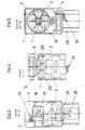
- This motor pinion (4) is Part of a gear arrangement, which further comprises a gear wheel (5), which as Spoke gear is formed, as can be seen from Figure 5.
- This Spoke gear (5) is rotatably connected to a shaft (6), which at the same time as Torsion bar works.
- the spoke gear (5) is together with the shaft (6) molded in one piece from plastic.
- a toothing (7) is integral with the spokes of the spoke gear (5) formed, which engages in a torsion spring, which in a torsion spring cassette (8) is arranged.
- This torsion spring causes the shaft (6) to turn de-energized state of the electric motor (3) such that a push rod (12) as far as possible into the interior of the housing.
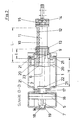
- An external thread (9) is arranged on a partial circumference of the shaft (6), as from of Figure 2 emerges. This external thread (9) on the outer circumference of the shaft (6) engages in a counter thread (10), which as an internal thread in a bore (11) the push rod (12) is formed.
- the push rod (12) is longitudinally displaceable in a labyrinth seal (13) Housing stored.
- the labyrinth seal is in one piece with the plastic parts of the first and second housing part (1, 2).
- Am in Figures 1 and 2 right end of the push rod (12) has a button (14) formed on it interchangeable and therefore to the respective application of Adaptable coupling part according to the invention electromotive actuator (15) carries.
- the shaft (6) has on the one hand a storage area (16) which is in a constriction (17) of the housing is arranged. Furthermore, the shaft (6) has an extension beyond the toothing (7) (18), which is arranged in a further shaft bearing (19) of the housing. So that the shaft (6) on both sides of the spoke gear (5) in the housing stored.
- the push rod (12) carries two opposite ones inside the housing Stop elements (20), which are box-shaped and integral with the Push rod (12) are molded from plastic.
- the box shape of the Teeing elements (20) thus forms a four-bar hinge with film hinges Housing stops (21) cooperates.
- These resilient stop elements (20) are intended to hit the push rod (12) cushion the housing and sudden and excessive torsion of the shaft (6) avoid.
- the two housing parts (1, 2) are interconnected by snap connections (24) connected.
- Plug contacts (25) are inserted into and through the housing wall Inserted the housing wall so that it continues in the electric motor (3) can be inserted and the electrical contacting of the electric motor with effect the remaining parts of a motor vehicle electrical system.
- the plug contacts (25) are in a connector basket (26) for protection against mechanical damage arranged in one piece with the housing parts (1, 2).
- the stroke of the push rod (12) in the housing is identified by (H) in FIG. 2.
- the length of the counter thread (10) of the push rod (12) is in the same figure (L) marked.
- the length of the thread (9) of the shaft (6) is in the same figure marked with (I).
- the length (L) of the counter thread (10) is greater than the stroke (H) of the push rod (12) in the housing is at least the same like this hub.
- the length (I) of the thread (9) is significantly smaller than the length (L) of the counter thread (10), and it is the thread (9) on the from Spoke gear (5) facing away from the shaft (6) so that between the thread (9) and the spoke gear (5) a shaft area of the shaft (6) is formed, which has no thread and in this respect a torsion of the shaft (6) in Area between the spoke gear (5) and the thread (9) allows.
- torsion of the shaft (6) is capable of the excess torque of the Electric motor (3) when the push rod (12) strikes the housing stops (21) to intercept the housing with the stop elements (20) and one Damage to the electromotive actuator according to the invention prevent.
- the spoke gear (5) also has the same purpose Allows torsion of the gear hub with respect to the ring gear.
- a Slip clutch is the special design of the electromotive actuator not required.
Landscapes
- Engineering & Computer Science (AREA)
- General Engineering & Computer Science (AREA)
- Mechanical Engineering (AREA)
- Lock And Its Accessories (AREA)
- Connection Of Motors, Electrical Generators, Mechanical Devices, And The Like (AREA)
- Power-Operated Mechanisms For Wings (AREA)
Description
- Figur 1
- einen Teilschnitt durch einen erfindungsgemäßen Stellantrieb in einer Seitenansicht;
- Figur 2
- einen Schnitt durch den erfindungsgemäßen Stellantrieb gemäß der Schnittlinie B-B in Figur 1;
- Figur 3
- einen Schnitt durch den erfindungsgemäßen Stellantrieb gemäß der Schnittlinie A-A in Figur 1;
- Figur 4
- einen Schnitt durch den Stellantrieb gemäß der Schnittlinie C-C in Figur 1 und
- Figur 5
- einen Schnitt durch den Stellantrieb gemäß der Schnittlinie D-D in Figur 1.
- 1
- erstes Gehäuseteil
- 2
- zweites Gehäuseteil
- 3
- Elektromotor
- 4
- Motorritzel auf Motorwelle
- 5
- Speichenzahnrad
- 6
- Welle / Torsionsstab
- 7
- Zahnung
- 8
- Torsionsfederkassette
- 9
- Außengewinde auf Teilumfang von (6)
- 10
- (Innengewinde) Gegengewinde
- 11
- Bohrung
- 12
- Schubstange
- 13
- Labyrinthdichtung
- 14
- Knopf
- 15
- Kupplungsteil
- 16
- Lagerbereich von (6)
- 17
- Einschnürung des Gehäuses
- 18
- Fortsatz
- 19
- Wellenlager
- 20
- Anschlagelemente, kastenförmig, Viergelenk mit Filmscharnier
- 21
- Gehäuseanschläge
- 22
- Wellenflansch
- 23
- Stirnseite von (12)
- 24
- Rastverbindung
- 25
- Steckkontakte in Gehäusewandung eingedrückt, im Motor eingesteckt
- 26
- Steckerkorb
- H
- Hub der Schubstange (12)
- L
- Länge des Gegengewindes
- l
- Länge des Gewindes
Claims (13)
- Elektromotorischer Stellantrieb für Kraftfahrzeuge, insbesondere für Zentralverriegelungen, mit einem Gehäuse, mit einem Elektromotor (3), der eine Welle (6) mit Gewinde (9) treibt, und mit einer Schubstange (12), die mit einem Gegengewinde (10) in das Gewinde (9) der Welle (6) eingreift, und die im Gehäuse längsverschieblich geführt ist, dadurch gekennzeichnet, daß die Länge (L) des Gegengewindes (10) der Schubstange (12) mindestens gleich dem Hub (H) der Schubstange (12) gegenüber dem Gehäuse ist, daß die Länge (I) des Gewindes (9) der Welle (6) kleiner ist als die Länge (L) des Gegengewindes (10) der Schubstange (12) und daß das Gewinde (9) der Welle (6) an der Abtriebsseite der Welle (6) angeordnet ist, so daß sich ein gewindefreier Wellenbereich ergibt, der bei der Bewegung der Schubstange (12) auf Gehäuseanschläge (21) eine Torsion der Welle (6) ermöglicht.
- Elektromotorischer Stellantrieb nach Anspruch 1, dadurch gekennzeichnet, daß die Länge (1) des Gewindes (9) der Welle (6) etwa ein Drittel der Länge (L) des Gegengewindes (10) der Schubstange (12) beträgt.
- Elektromotorischer Stellantrieb nach Anspruch 1, dadurch gekennzeichnet, daß das Gewinde (9) der Welle (6) 3 bis 5, vorzugsweise 4 Gewindegänge aufweist.
- Elektromotorischer Stellantrieb nach Anspruch 1, dadurch gekennzeichnet, daß das Gewinde (9) der Welle (6) nur einen Teilumfang der Welle (6) umfaßt.
- Elektromotorischer Stellantrieb nach Anspruch 1, dadurch gekennzeichnet, daß zwischen Elektromotor (3) und Welle (6) eine Getriebeanordnung vorgesehen ist, deren Motorritzel (4) ein drehfest mit der Welle (6) verbundenes Zahnrad (5) treibt und daß das Gewinde (9) auf der vom Zahnrad (5) abgewandten Seite der Welle (6) angeordnet ist.
- Elektromotorischer Stellantrieb nach Anspruch 5, dadurch gekennzeichnet, daß das Zahnrad (5) ein Speichenzahnrad ist und daß die Speichen des Zahnrades (5) eines Zahnung (7) aufweisen, die in eine Torsionsfeder einer Torsionsfederkassette (8) eingreifen.
- Elektromotorischer Stellantrieb nach Anspruch 5, dadurch gekennzeichnet, daß auf beiden Seiten des Zahnrades (5) ein Lagerbereich (16) bzw. ein Fortsatz (18) der Welle (6) vorgesehen ist, der mit einer Einschnürung (17) des Gehäuses bzw. einem Wellenlager (19) korrespondiert.
- Elektromotorischer Stellantrieb nach Anspruch 1, dadurch gekennzeichnet, daß das Gewinde (9) der Welle (6) ein Außengewinde ist und daß das Gegengewinde (10) der Schubstange (12) ein Innengewinde ist, das in einer Bohrung (11) der Schubstange (12) angeordnet ist.
- Elektromotorischer Stellantrieb nach Anspruch 1, dadurch gekennzeichnet, daß die Schubstange (12) Anschlagelemente (20) aufweist, die mit Gehäuseanschlägen (21) zusammenwirken.
- Elektromotorischer Stellantrieb nach Anspruch 9, dadurch gekennzeichnet, daß die Anschlagelemente (20) kastenförmig im Sinne eines Viergelenks mit Filmscharnieren ausbildet sind.
- Elektromotorischer Stellantrieb nach Anspruch 1, dadurch gekennzeichnet, daß die Welle (6) auf der vom Gewinde (9) abgewandten Seite einen Wellenflansch (22) aufweist, der mit einer Stirnseite (23) der Schubstange (12) zusammenwirkt.
- Elektromotorischer Stellantrieb nach Anspruch 1, dadurch gekennzeichnet, daß elektrische Steckkontakte (25) in die Gehäusewandung eingedrückt und zugleich in den Elektromotor (3) zur elektrischen Verbindung eingesteckt sind.
- Elektromotorischer Stellantrieb nach Anspruch 1, dadurch gekennzeichnet, daß die Schubstange (12) in einer einstückig mit dem Gehäuse ausgebildeten Labyrinthdichtung (13) geführt ist.
Applications Claiming Priority (2)
| Application Number | Priority Date | Filing Date | Title |
|---|---|---|---|
| DE19535437 | 1995-09-23 | ||
| DE19535437A DE19535437C2 (de) | 1995-09-23 | 1995-09-23 | Elektromotorischer Stellantrieb für Kraftfahrzeuge |
Publications (3)
| Publication Number | Publication Date |
|---|---|
| EP0764751A1 EP0764751A1 (de) | 1997-03-26 |
| EP0764751B1 true EP0764751B1 (de) | 2001-05-16 |
| EP0764751B2 EP0764751B2 (de) | 2005-02-09 |
Family
ID=7773002
Family Applications (1)
| Application Number | Title | Priority Date | Filing Date |
|---|---|---|---|
| EP96114670A Expired - Lifetime EP0764751B2 (de) | 1995-09-23 | 1996-09-13 | Elektromotorischer Stellantrieb für Kraftfahrzeuge |
Country Status (3)
| Country | Link |
|---|---|
| EP (1) | EP0764751B2 (de) |
| DE (2) | DE19535437C2 (de) |
| ES (1) | ES2159335T3 (de) |
Families Citing this family (10)
| Publication number | Priority date | Publication date | Assignee | Title |
|---|---|---|---|---|
| DE29705380U1 (de) * | 1997-03-25 | 1997-06-12 | Hella Kg Hueck & Co, 59557 Lippstadt | Elektromotorischer Stellantrieb für Kraftfahrzeuge |
| DE19724877C2 (de) * | 1997-06-12 | 2001-06-28 | Hella Kg Hueck & Co | Elektromotorischer Stellantrieb für Kraftfahrzeuge mit Geräuschdämpfer |
| DE19908155A1 (de) * | 1999-02-25 | 2000-08-31 | Hella Kg Hueck & Co | Elektromotorische Stellvorrichtung für ein Kraftfahrzeug |
| DE10039839A1 (de) | 2000-08-10 | 2002-05-02 | Kiekert Ag | Lenkradschlosseinheiten |
| DE10239925B4 (de) * | 2002-08-30 | 2006-09-14 | Hella Kgaa Hueck & Co. | Stellantrieb für Kraftfahrzeuge |
| DE102004012573A1 (de) * | 2004-03-12 | 2005-10-06 | Kiekert Ag | Stellantrieb für Kraftfahrzeuge |
| DE102004063814A1 (de) * | 2004-12-30 | 2006-07-13 | Kiekert Ag | Adapter zur Verwendung mit einem elektronischen Kleinstantrieb |
| DE102008057860A1 (de) * | 2008-11-18 | 2010-07-22 | Bayerische Motoren Werke Aktiengesellschaft | Tankklappenmodul |
| DE102012218650A1 (de) | 2012-10-12 | 2014-02-06 | Kiekert Ag | Stelleinheit für ein Kraftfahrzeugschloss nebst Herstellungsverfahren |
| DE102014014620A1 (de) | 2014-09-25 | 2016-03-31 | Kiekert Aktiengesellschaft | Sicherungseinrichtung für ein elektronisches Gerät in einem Kraftfahrzeug |
Citations (5)
| Publication number | Priority date | Publication date | Assignee | Title |
|---|---|---|---|---|
| DE3247490A1 (de) * | 1982-12-22 | 1984-06-28 | Deutsche Babcock Werke AG, 4200 Oberhausen | Armatur |
| DE3309962A1 (de) * | 1983-03-19 | 1984-09-20 | Eberhard Dipl.-Ing. 2105 Seevetal Becker | Elektrisch fernbedienbares einsteckschloss |
| US4573723A (en) * | 1983-11-26 | 1986-03-04 | Nippondenso Co., Ltd. | System including bi-directional drive mechanism |
| DE3631043C1 (en) * | 1986-09-12 | 1988-03-17 | Franz Dipl-Ing Schmidt | Door fastening, especially for motor vehicles |
| EP0265973A1 (de) * | 1986-10-31 | 1988-05-04 | Murakami Kaimeido Co., Ltd | Einstellvorrichtung für Rüchblickspiegel |
Family Cites Families (11)
| Publication number | Priority date | Publication date | Assignee | Title |
|---|---|---|---|---|
| US2517373A (en) * | 1949-06-29 | 1950-08-01 | Air Associates Inc | Load limiting drive mechanism |
| US2778239A (en) * | 1953-04-06 | 1957-01-22 | Vaino A Hoover | Mechanical actuator |
| GB1005520A (en) * | 1964-02-05 | 1965-09-22 | North American Aviation Inc | An electrically operated extensible element |
| DE8621592U1 (de) * | 1986-08-12 | 1986-10-09 | Kiekert Gmbh & Co Kg, 42579 Heiligenhaus | Stelltrieb für einen Kraftfahrzeug-Türverschluß |
| DE3631163A1 (de) * | 1986-09-12 | 1988-03-24 | Vdo Schindling | Elektromechanisches stellglied |
| EP0287860A3 (de) * | 1987-03-31 | 1989-06-07 | Asmo Co., Ltd. | Mechanismus zum Umwandeln von Drehbewegung in eine hin- und hergehende Bewegung |
| FR2623587B1 (fr) * | 1987-11-23 | 1992-04-03 | Rockwell Cim | Dispositif motoreducteur d'entrainement d'une piece a controle d'effort de securite |
| US4850466A (en) * | 1988-05-19 | 1989-07-25 | General Motors Corporation | Clutch for power door lock actuator |
| GB2224546A (en) * | 1988-08-23 | 1990-05-09 | Rockwell Automotive Body Syst | Vehicle door latch and like actuators |
| US4927203A (en) * | 1989-02-17 | 1990-05-22 | United Technologies Electro Systems, Inc. | Boot sealing and attachment means for automotive door lock actuators and the like |
| EP0512139A1 (de) * | 1991-05-07 | 1992-11-11 | Siemens Aktiengesellschaft | Elektromotorischer Stellantrieb |
-
1995
- 1995-09-23 DE DE19535437A patent/DE19535437C2/de not_active Revoked
-
1996
- 1996-09-13 DE DE59606899T patent/DE59606899D1/de not_active Expired - Lifetime
- 1996-09-13 ES ES96114670T patent/ES2159335T3/es not_active Expired - Lifetime
- 1996-09-13 EP EP96114670A patent/EP0764751B2/de not_active Expired - Lifetime
Patent Citations (5)
| Publication number | Priority date | Publication date | Assignee | Title |
|---|---|---|---|---|
| DE3247490A1 (de) * | 1982-12-22 | 1984-06-28 | Deutsche Babcock Werke AG, 4200 Oberhausen | Armatur |
| DE3309962A1 (de) * | 1983-03-19 | 1984-09-20 | Eberhard Dipl.-Ing. 2105 Seevetal Becker | Elektrisch fernbedienbares einsteckschloss |
| US4573723A (en) * | 1983-11-26 | 1986-03-04 | Nippondenso Co., Ltd. | System including bi-directional drive mechanism |
| DE3631043C1 (en) * | 1986-09-12 | 1988-03-17 | Franz Dipl-Ing Schmidt | Door fastening, especially for motor vehicles |
| EP0265973A1 (de) * | 1986-10-31 | 1988-05-04 | Murakami Kaimeido Co., Ltd | Einstellvorrichtung für Rüchblickspiegel |
Also Published As
| Publication number | Publication date |
|---|---|
| ES2159335T3 (es) | 2001-10-01 |
| DE19535437C2 (de) | 2001-10-18 |
| DE19535437A1 (de) | 1997-04-03 |
| DE59606899D1 (de) | 2001-06-21 |
| EP0764751B2 (de) | 2005-02-09 |
| EP0764751A1 (de) | 1997-03-26 |
Similar Documents
| Publication | Publication Date | Title |
|---|---|---|
| EP0223921B1 (de) | Parksperre für automatische Getriebe von Kraftfahrzeugen | |
| DE102007060149A1 (de) | Teleskopierbare Lenkspindelanordnung | |
| EP0764751B1 (de) | Elektromotorischer Stellantrieb für Kraftfahrzeuge | |
| EP1110828A2 (de) | Verriegelungsvorrichtung | |
| DE4109920A1 (de) | Elektrisch angetriebene servo-lenkvorrichtung | |
| DE102019133406A1 (de) | Schubstangenführungsbaugruppe, Lenkaktuator sowie Verfahren zur Herstellung einer Schubstangenführungsbaugruppe | |
| WO2011038719A1 (de) | Verschiebegelenk | |
| DE102017115464A1 (de) | Überlastkupplung für einen Antriebsstrang | |
| DE3619340C2 (de) | ||
| DE102020213568A1 (de) | Verbindung zwischen einem Schalthebel und einer Verbindungsstange einer Parksperre eines Kraftfahrzeugs | |
| DE102019100153B4 (de) | Übertragungstrennmechanismus eines Untersetzungsgetriebes | |
| WO2006122603A1 (de) | Lenkgetriebe | |
| DE102013210074A1 (de) | Antriebseinrichtung | |
| EP4230896A1 (de) | Spindelbaugruppe für eine spindelantriebsvorrichtung | |
| DE102010046887B4 (de) | Verschiebegelenk | |
| DE102021103622A1 (de) | Dreh-getriebeanordnung zur vergrösserung des hartanschlag-motorweges | |
| WO2017211513A1 (de) | Aktuator für eine hinterachslenkung | |
| DE102020200266A1 (de) | Mit einem Kettenantrieb betätigbare schiebesteife Schubkette | |
| EP1764462B1 (de) | Getriebe für eine Panikstange | |
| WO1994026574A1 (de) | Drehschieberventil für hilfskraftlenkungen von kraftfahrzeugen | |
| EP1659250A1 (de) | Fenster, Tür oder dergleichen mit einer Eckumlenkung | |
| DE19650716C1 (de) | Exzentergetriebe | |
| DE102004052180B3 (de) | Abklappantrieb für einen Kfz-Außenrückblickspiegel | |
| DE69227341T2 (de) | Betätigungsvorrichtung, zur Betätigung des Sicherheitshebels eines Kraftwagentürschlosses | |
| DE102019110902A1 (de) | Spindelantrieb für ein Verschlusselement eines Kraftfahrzeugs |
Legal Events
| Date | Code | Title | Description |
|---|---|---|---|
| PUAI | Public reference made under article 153(3) epc to a published international application that has entered the european phase |
Free format text: ORIGINAL CODE: 0009012 |
|
| AK | Designated contracting states |
Kind code of ref document: A1 Designated state(s): DE ES FR GB IT |
|
| 17P | Request for examination filed |
Effective date: 19970701 |
|
| 17Q | First examination report despatched |
Effective date: 19990317 |
|
| GRAG | Despatch of communication of intention to grant |
Free format text: ORIGINAL CODE: EPIDOS AGRA |
|
| GRAG | Despatch of communication of intention to grant |
Free format text: ORIGINAL CODE: EPIDOS AGRA |
|
| GRAH | Despatch of communication of intention to grant a patent |
Free format text: ORIGINAL CODE: EPIDOS IGRA |
|
| ITF | It: translation for a ep patent filed | ||
| GRAH | Despatch of communication of intention to grant a patent |
Free format text: ORIGINAL CODE: EPIDOS IGRA |
|
| GRAA | (expected) grant |
Free format text: ORIGINAL CODE: 0009210 |
|
| AK | Designated contracting states |
Kind code of ref document: B1 Designated state(s): DE ES FR GB IT |
|
| PG25 | Lapsed in a contracting state [announced via postgrant information from national office to epo] |
Ref country code: GB Free format text: LAPSE BECAUSE OF FAILURE TO SUBMIT A TRANSLATION OF THE DESCRIPTION OR TO PAY THE FEE WITHIN THE PRESCRIBED TIME-LIMIT Effective date: 20010516 Ref country code: FR Free format text: LAPSE BECAUSE OF NON-PAYMENT OF DUE FEES Effective date: 20010516 |
|
| REF | Corresponds to: |
Ref document number: 59606899 Country of ref document: DE Date of ref document: 20010621 |
|
| GBT | Gb: translation of ep patent filed (gb section 77(6)(a)/1977) |
Effective date: 20010731 |
|
| REG | Reference to a national code |
Ref country code: ES Ref legal event code: FG2A Ref document number: 2159335 Country of ref document: ES Kind code of ref document: T3 |
|
| ET | Fr: translation filed | ||
| REG | Reference to a national code |
Ref country code: GB Ref legal event code: IF02 |
|
| PLBQ | Unpublished change to opponent data |
Free format text: ORIGINAL CODE: EPIDOS OPPO |
|
| PLBI | Opposition filed |
Free format text: ORIGINAL CODE: 0009260 |
|
| 26 | Opposition filed |
Opponent name: SIEMENS AG Effective date: 20020117 |
|
| PLBF | Reply of patent proprietor to notice(s) of opposition |
Free format text: ORIGINAL CODE: EPIDOS OBSO |
|
| PLBF | Reply of patent proprietor to notice(s) of opposition |
Free format text: ORIGINAL CODE: EPIDOS OBSO |
|
| PGFP | Annual fee paid to national office [announced via postgrant information from national office to epo] |
Ref country code: GB Payment date: 20040908 Year of fee payment: 9 Ref country code: FR Payment date: 20040908 Year of fee payment: 9 |
|
| PGFP | Annual fee paid to national office [announced via postgrant information from national office to epo] |
Ref country code: ES Payment date: 20040929 Year of fee payment: 9 |
|
| RAP2 | Party data changed (patent owner data changed or rights of a patent transferred) |
Owner name: HELLA KGAA HUECK & CO. |
|
| PUAH | Patent maintained in amended form |
Free format text: ORIGINAL CODE: 0009272 |
|
| STAA | Information on the status of an ep patent application or granted ep patent |
Free format text: STATUS: PATENT MAINTAINED AS AMENDED |
|
| 27A | Patent maintained in amended form |
Effective date: 20050209 |
|
| AK | Designated contracting states |
Kind code of ref document: B2 Designated state(s): DE ES FR GB IT |
|
| PG25 | Lapsed in a contracting state [announced via postgrant information from national office to epo] |
Ref country code: ES Free format text: LAPSE BECAUSE OF FAILURE TO SUBMIT A TRANSLATION OF THE DESCRIPTION OR TO PAY THE FEE WITHIN THE PRESCRIBED TIME-LIMIT Effective date: 20050520 |
|
| GBV | Gb: ep patent (uk) treated as always having been void in accordance with gb section 77(7)/1977 [no translation filed] |
Effective date: 20010516 |
|
| EN | Fr: translation not filed | ||
| PGFP | Annual fee paid to national office [announced via postgrant information from national office to epo] |
Ref country code: IT Payment date: 20060930 Year of fee payment: 11 |
|
| PG25 | Lapsed in a contracting state [announced via postgrant information from national office to epo] |
Ref country code: IT Free format text: LAPSE BECAUSE OF NON-PAYMENT OF DUE FEES Effective date: 20070913 |
|
| PGFP | Annual fee paid to national office [announced via postgrant information from national office to epo] |
Ref country code: DE Payment date: 20150908 Year of fee payment: 20 |
|
| REG | Reference to a national code |
Ref country code: DE Ref legal event code: R071 Ref document number: 59606899 Country of ref document: DE |