EP0763759A2 - Méthode et appareil de décharge électrique - Google Patents
Méthode et appareil de décharge électrique Download PDFInfo
- Publication number
- EP0763759A2 EP0763759A2 EP96306035A EP96306035A EP0763759A2 EP 0763759 A2 EP0763759 A2 EP 0763759A2 EP 96306035 A EP96306035 A EP 96306035A EP 96306035 A EP96306035 A EP 96306035A EP 0763759 A2 EP0763759 A2 EP 0763759A2
- Authority
- EP
- European Patent Office
- Prior art keywords
- alternating voltage
- electric discharge
- frequency
- discharge electrodes
- current
- Prior art date
- Legal status (The legal status is an assumption and is not a legal conclusion. Google has not performed a legal analysis and makes no representation as to the accuracy of the status listed.)
- Withdrawn
Links
Images


Classifications
-
- F—MECHANICAL ENGINEERING; LIGHTING; HEATING; WEAPONS; BLASTING
- F02—COMBUSTION ENGINES; HOT-GAS OR COMBUSTION-PRODUCT ENGINE PLANTS
- F02P—IGNITION, OTHER THAN COMPRESSION IGNITION, FOR INTERNAL-COMBUSTION ENGINES; TESTING OF IGNITION TIMING IN COMPRESSION-IGNITION ENGINES
- F02P23/00—Other ignition
- F02P23/04—Other physical ignition means, e.g. using laser rays
-
- G—PHYSICS
- G02—OPTICS
- G02B—OPTICAL ELEMENTS, SYSTEMS OR APPARATUS
- G02B6/00—Light guides; Structural details of arrangements comprising light guides and other optical elements, e.g. couplings
- G02B6/24—Coupling light guides
- G02B6/255—Splicing of light guides, e.g. by fusion or bonding
- G02B6/2551—Splicing of light guides, e.g. by fusion or bonding using thermal methods, e.g. fusion welding by arc discharge, laser beam, plasma torch
-
- F—MECHANICAL ENGINEERING; LIGHTING; HEATING; WEAPONS; BLASTING
- F02—COMBUSTION ENGINES; HOT-GAS OR COMBUSTION-PRODUCT ENGINE PLANTS
- F02P—IGNITION, OTHER THAN COMPRESSION IGNITION, FOR INTERNAL-COMBUSTION ENGINES; TESTING OF IGNITION TIMING IN COMPRESSION-IGNITION ENGINES
- F02P15/00—Electric spark ignition having characteristics not provided for in, or of interest apart from, groups F02P1/00 - F02P13/00 and combined with layout of ignition circuits
- F02P15/10—Electric spark ignition having characteristics not provided for in, or of interest apart from, groups F02P1/00 - F02P13/00 and combined with layout of ignition circuits having continuous electric sparks
-
- F—MECHANICAL ENGINEERING; LIGHTING; HEATING; WEAPONS; BLASTING
- F02—COMBUSTION ENGINES; HOT-GAS OR COMBUSTION-PRODUCT ENGINE PLANTS
- F02P—IGNITION, OTHER THAN COMPRESSION IGNITION, FOR INTERNAL-COMBUSTION ENGINES; TESTING OF IGNITION TIMING IN COMPRESSION-IGNITION ENGINES
- F02P3/00—Other installations
- F02P3/02—Other installations having inductive energy storage, e.g. arrangements of induction coils
- F02P3/04—Layout of circuits
- F02P3/05—Layout of circuits for control of the magnitude of the current in the ignition coil
- F02P3/051—Opening or closing the primary coil circuit with semiconductor devices
- F02P3/053—Opening or closing the primary coil circuit with semiconductor devices using digital techniques
Definitions
- the present invention relates in general to electric discharge method and apparatus and, more particularly, to method and apparatus for supplying an electrical energy to a pair of discharge electrodes spaced apart from each other to cause an electric discharge in a gap between the discharge electrodes.
- the method and apparatus may be applied to fusion splicing method and apparatus for splicing a pair of optical fibers to each other by exerting the electric discharge upon the optical fibers and, additionally, applied to dust collecting method and apparatus, electrostatic painting method and apparatus, and an electric discharge tube.
- the Japanese Provisional Patent No. 61-22555 teaches an electric discharge apparatus that is shown in Fig. 16 as comprising a capacitor 102, a discharge electrode unit including a pair of discharge electrodes 103a and 103b connected to the capacitor 102 in series, direct current power supply 104 generating a direct current, a boosting transformer 105 comprising a primary winding 105a, a secondary winding 105b and a center tap 105c, switching transistors 106 and 107 having three terminals consisting of base, emitter and collector terminal, diodes 108 and 109 each having an anode and a cathode, a direct current high voltage generating circuit 110 receiving an AC voltage to generate a direct current high voltage, and a high impedance resistance unit 111 for charging the capacitor 102.
- DC direct current
- AC high impedance resistance unit
- the DC power supply 104 has two output terminals consisting of a first output terminal which is electrically connected to the emitter terminals of the switching transistors 106 and 107, and a second output terminal which is electrically connected to the center tap 105c of the boosting transformer 105.
- the collector terminal of the switching transistor 106 is connected to one end of the primary winding 105a of the boosting transformer 105, while the collector terminal of the switching transistor 107 is connected to the other end of the primary winding 105a of the boosting transformer 105.
- the diodes 108 and 109 are inversely connected in parallel to the switching transistors 106 and 107, respectively.
- the secondary winding 105b of the boosting transformer 105 is connected at its one end to the discharge electrode 103a through the capacitor 102, and at its the other end to the discharge electrode 103b.
- the DC high voltage generating circuit 110 has a pair of input terminals respectively connected to ends of the secondary winding 105b of the boosting transformer 105, and an output terminal connected to one end of the high impedance resistance unit 111.
- the other end of the high impedance resistance unit 111 is connected to a current carrying line between the capacitor 102 and the discharge electrode 103a.
- the base terminals of the switching transistors 106 and 107 are connected to and driven by a driving circuit (not shown).
- the switching transistor 106 When the switching transistor 106 is driven by the driving circuit to turn on the electric current through one of two parts of the primary winding 105a divided by the center tap 105c, the switching transistor 107 is driven by the driving circuit to turn off the electric current through the other of the two parts of the primary winding 105a, and vice versa.
- the boosting transformer 105 is operated to induce an alternating voltage in its secondary winding. Since the discharge electrode unit 103 is considered to be a load having an extremely high impedance, an electric discharge current is not allowed to flow through a gap between the discharge electrodes 103a and 103b for an instant.
- the DC high voltage generating circuit 110 receives the AC voltage induced in the secondary winding 105b of the boosting transformer 105 to generate the DC voltage.
- the DC voltage is applied to the capacitor 102 through the high impedance resistance unit 111 to cause a small electric current to flow through the capacitor 102 and, as a consequence, the capacitor 102 is charged up during a period, for example, from ten cycles to several tens of cycles.
- the discharge electrodes 103a and 103b receive a voltage which is shown by a wave form WF1 in Fig. 18(a) as ascending gradually in notched shape.
- the DC high voltage generating circuit 110 may be a multiple voltage rectifier unit that is shown in Fig. 17 as comprising diodes 110a and 110b, and a capacitor l10c.
- the diode 110a has an anode and a cathode, the anode being connected to a current carrying line between one end of the secondary winding 105b and the capacitor 102.
- the diode 110b has an anode connected to the cathode of the diode 110a and a cathode connected to the high impedance resistance unit 111.
- the capacitor 110c has a pair of plates, one of the plates being connected to the cathode of the diode 110a and the anode of the diode 110b, and the other of the plates being connected to a current carrying line between the other end of the secondary winding 105b and the discharge electrode 103b.
- the voltage across the capacitors 102 is increased.
- a dielectric breakdown is caused in the gap between the discharge electrodes 103a and 103b and, accordingly, an electric discharge current is allowed to flow through the gap between the discharge electrodes 103a and 103b as understood from the wave form WF2 of the discharge current shown in Fig. 18(b).
- the electric discharges are repeated in simultaneous relationship to half of a cycle of the AC voltage across the discharge electrodes 103a and 103b under the condition that the voltage across the discharge electrodes 103a and 103b is considerably lower than the trigger voltage.
- a series resonant current flows from the boosting transformer 105 to the discharge electrodes 103a and 103b through a series circuit defined by a leakage inductance of the boosting transformer 105 and a capacitance of the capacitor 102.
- the diodes 106 and 107 are operated to return the electrical power from a secondary side circuit including the secondary winding 105b back to the DC power supply 104.
- the electric discharge apparatus When the electric discharge apparatus thus constructed serves as an optical fiber fusion splicing apparatus, a pair of optical fibers are spliced to each other by the energy of the electric discharge between the discharge electrodes 103a and 103b.
- the electric discharge produced by the optical fiber fusion splicing apparatus may be used to remove a jacket cover from the optical fiber.
- the optical fiber fusion splicing apparatus is required to heat the jacket cover at a relatively low temperature with respect to a temperature held during the fusion splicing.
- the electric discharge current In order to control the temperature of the electric discharge, the electric discharge current may be controlled. When the jacket cover is removed by the energy of the electric discharge from the optical fiber, the electric discharge current is controlled to decrease.
- the electric discharge When the optical fibers are spliced by the energy of the electric discharge to each other, the electric discharge is controlled to increase.
- a drawback is, however, encountered in a prior-art electric discharge apparatus of the above described nature in that an electrical circuit forming the apparatus is increased in size and complexity.
- the reason for this is that the electric discharge apparatus is required to comprise a special circuit such as the DC voltage generating unit 110.
- the Japanese Provisional Patent No. 62-40948 discloses an electric discharge current controlling method and an electric discharge current stabilizing method.
- the former controlling method comprises a step of controlling the electric discharge current by varying a period during which the switching transistors are in the "ON" condition.
- the latter stabilizing method comprises a step of stabilizing the electric discharge current by performing a feedback control on the basis of an integrated electric discharge current, and by controlling the period during which the switching transistors are in the "ON" condition.
- the electric discharge apparatus is required to comprise a transformer for the DC/DC converter. This means that devices or circuit elements forming the electric discharge apparatus is increased in number and, accordingly, that the electric discharge apparatus becomes large-sized.
- a method of supplying an electrical energy to a pair of discharge electrodes spaced apart from each other to cause an electric discharge in a gap between the discharge electrodes comprises the step (a) of preparing an alternating voltage generator for generating, as the electrical energy, an alternating voltage having a frequency, and a capacitor connected to the discharge electrodes in series.
- the alternating voltage generator has a series resonant frequency.
- the method further comprises the step (b) of applying the alternating voltage of the alternating voltage generator to the discharge electrodes through the capacitor, and the step (c) of setting the frequency of the alternating voltage approximately to the series resonant frequency of the alternating voltage generator to cause a dielectric breakdown in and allow an electric discharge current to flow through the gap between the discharge electrodes.
- a method of supplying an electrical energy to a pair of discharge electrodes spaced apart from each other to cause an electric discharge in a gap between the discharge electrodes comprises the step (a) of preparing an alternating voltage generator for generating, as the electrical energy, an alternating voltage having a frequency, and a capacitor connected to the discharge electrodes in series.
- the alternating voltage generator has a series resonant frequency.
- the method further comprises the step (b) of applying the alternating voltage of the alternating voltage generator to the discharge electrodes through the capacitor, and the step of (c) of approximating the frequency of the alternating voltage to the series resonant frequency of the alternating voltage generator to cause a dielectric breakdown in and allow an electric discharge current to flow through the gap between the discharge electrodes.
- an apparatus for supplying an electrical energy to a pair of discharge electrodes spaced apart from each other to cause an electric discharge in a gap between the discharge electrodes.
- the apparatus comprises a capacitor connected to the discharge electrodes in series, and an alternating voltage generator for generating, as the electrical energy, an alternating voltage having a frequency to apply the alternating voltage to the discharge electrodes through the capacitor.
- the alternating voltage generator has a series resonant frequency.
- the apparatus further comprises frequency setting means for setting the frequency of the alternating voltage approximately to the series resonant frequency of the alternating voltage generator to cause a dielectric breakdown in and allow an electric discharge current to flow through the gap between the discharge electrodes.
- an apparatus for supplying an electrical energy to a pair of discharge electrodes spaced apart from each other to cause an electric discharge in a gap between the discharge electrodes.
- the apparatus comprises a capacitor connected to the discharge electrodes in series, and an alternating voltage generator for generating, as the electrical energy, an alternating voltage having a frequency to apply the alternating voltage to the discharge electrodes through the capacitor.
- the alternating voltage generator has a series resonant frequency.
- the apparatus further comprises frequency approximating means for approximating the frequency of the alternating voltage to the series resonant frequency of the alternating voltage generator to cause a dielectric breakdown in and allow an electric discharge current to flow through the gap between the discharge electrodes.
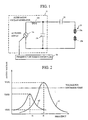
- the electric discharge apparatus comprises an alternating voltage generator 11, a capacitor 12 and a discharge electrode unit 13 including a pair of discharge electrodes 13a and 13b, and a frequency switching controller 14.
- the alternating voltage generator 11 is shown in Fig. 1 as comprising an alternating current power supply (hereinlater referred to as "AC power supply” for brevity) 11a generating an alternating voltage, an inductance element 11b connected to the AC power supply 11 in series, and a capacitance element 11c connected in parallel to a series connection of the AC power supply 11a and the inductance element 11b at a pair of connection points which correspond to a pair of output terminals of the alternating voltage generator 11.
- One of the output terminals of the alternating voltage generator 11 is connected to the discharge electrode 13a by way of the capacitor 12, while the other of the output terminals of the alternating voltage generator 11 is connected to the discharge electrode 13b.
- the frequency switching controller 14 is designed to control the alternating voltage generator 11 to regulate the frequency of the alternating voltage supplied from the AC power supply lla.
- the inductance element 11b is for example a choking coil. If the frequency of the alternating voltage supplied from the AC power supply 11a is set to a special value, the inductance element 11b may be formed by a self-inductance of a current carrying line of the alternating voltage generator 11. If the alternating voltage generator 11 is so constructed as to include a transformer, the inductance element 11b may be formed by a leakage inductance of the transformer. It is natural that the inductance element 11b may be obtained by combining the foregoing substitution techniques.
- the capacitance element 11c may comprise a capacitor, if however desired, the capacitance element 11c may be formed by a stray capacitance of a circuit forming the alternating voltage generator 11, or by a combination of the capacitor 11c and the stray capacitance.
- the discharge electrode unit 13 Since the discharge electrodes 13a and 13b are spaced apart from each other, the discharge electrode unit 13 is held in a high impedance condition before an electric discharge is caused in a gap between the discharge electrodes 13a and 13b.
- the alternating voltage generator 11 has merely a load which is regarded as a series connection of the inductance element 11b and the capacitance element 11c and, as a result, the alternating voltage generator 11 has a series resonant frequency f1 defined by the inductance element 11b and the capacitance element 11c.
- the frequency of the alternating voltage supplied from the AC power supply 11a When the frequency of the alternating voltage supplied from the AC power supply 11a is set approximately to the series resonant frequency of the alternating voltage generator 11, an extremely high series resonant voltage is produced at the output terminals of the alternating voltage generator 11.
- the frequency of the alternating voltage supplied from the AC power supply 11a may be set just to the series resonant frequency of the alternating voltage generator 11, or to a frequency that is in the vicinity of the series resonant frequency of the alternating voltage generator 11.
- the produced series resonant voltage is divided into two voltages respectively applied to the capacitor 12 and the discharge electrode unit 13.
- the voltage across the discharge electrodes 13a and 13b is represented by a wave form WF3 shown in Fig. 3(a) which has absolute voltage peaks increased step by step with the lapse of time.
- the determinations of the output voltage of the AC power supply 11a and the circuit constant of the alternating voltage generator 11 result in the fact that, after the AC power supply 11a start to supply the alternating voltage, the voltage across the discharge electrodes 13a and 13b is varied as shown in Fig. 3(a). After several repetitions of the cycle of the voltage variation shown in Fig. 3(a), the electric discharge between the discharge electrodes 13a and 13b is caused to start. As a result, the electrical current flows through the gap between the discharge electrodes 13a and 13b as shown in Fig. 3(b). Although the electric discharge is shown in Figs. 3(a) and 3(b) as starting at the positive voltage peak across the discharge electrodes 13a and 13b, the electric discharge may start at the negative voltage peak because of the fact that the start of the electric discharge is independent of the electric polarity.
- the gap between the discharge electrodes 13a and 13b corresponds to a load having a low impedance.
- the capacitor 12 is connected to the capacitance element 11c in parallel and, as a consequence, that the inductance element 11b and the series connection circuit of the capacitance element 11c and the capacitor 12 collectively serve a load bored by the AC power supply 11a.
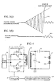
- the alternating voltage generator 11 and the capacitor 12 collectively forms a series resonant circuit which has a resonant characteristic represented by a curve C2 shown in Fig. 2.
- the capacitor 12 Since the capacitor 12 is added to the alternating voltage generator 11 to form the series resonant circuit after the start of the electric discharge, the output voltage of the alternating voltage generator 11 is peaked at a series resonant frequency f2 to reach a voltage peak V2(f2).
- the series resonant frequency f2 of the resonant circuit including the capacitor 12 is lower than the series resonant frequency f1 of the alternating voltage generator 11.
- the output voltage of the alternating generator 11 is equal to or in the vicinity of a voltage V2(f1) defining a point on the curve C2 in cooperation with the frequency f1. Not only is the voltage V2(f1) lower than the voltage peak V2(f2), but the electric discharge current in the frequency f1 is also smaller than that in the frequency f2. If the output voltage V2(f1) is enough for the electric discharge apparatus, the apparatus has no need to control the frequency of the alternating voltage of the AC power supply 11a after the start of the electric discharge.
- the discharge current in the frequency f1 is smaller than a desired value
- the discharge current can be increased by controlling the frequency of the alternating voltage of the AC power supply 11a.
- the frequency of the alternating voltage of the AC power supply 11a is set for example to the series resonant frequency f2
- the voltage across the discharge electrodes 13a and 13b at that time becomes largest.
- the discharge electrode unit 13 allows a large electric discharge current to flow through the gap between the discharge electrodes 13a and 13b.
- the frequency switching controller 14 is adapted to regulate the frequency of the alternating voltage of the AC power supply 11a to adjust the electric discharge current to a desired current value.
- the frequency of the alternating voltage of the AC power supply 11a may be variable throughout a frequency range between the series resonant frequencies f1 and f2.
- the electric discharge current in the frequency f1 exceeds the desired current value, the electric discharge current can be decreased by adjusting the frequency of the alternating voltage of the AC power supply 11a to a frequency level that is higher than the frequency f1. If, however, it is desired that the electric discharge current is drastically decreased, the foregoing control techniques are unsuitable to decrease the electric discharge current. That is because the inclination of the curve C2 becomes smaller as the frequency approaches the frequency f1 as shown in Fig. 2. This inconvenience is solved, for example, by decreasing the output voltage of the AC power supply 11a. It is noted that the output voltage of the AC power supply 11a is held at a voltage level higher than the discharge voltage across the discharge electrodes 30a and 30b while the electric discharge is started and maintained.
- the electric discharge apparatus may include a plurality of AC power supplies which have different from one another in frequency of output voltage. If the AC power supplies are prepared, the electric discharge apparatus may further comprise means for selecting one of the AC power supplies to control the electric discharge current.
- the selecting means may comprise a switching unit which is manually operated by an operator which is automatically operated. The start of the electric discharge is detected by the operator or a discharge detecting unit automatically operated.
- the discharge detecting unit may comprise, for example, a device for detecting the start of the electric discharge by sensing the light of the electric discharge.
- the electric discharge apparatus may further comprise a timer device for measuring an elapsed time from the start of the electric discharge. When the timer device detects that the elapsed time exceeds a predetermined time, the timer device recognizes that the electric discharge is started and informs it the operator or the automatically operated switching unit.
- the electric discharge apparatus according to the present invention has an advantage over a prior-art apparatus in rendering the circuit small-sized and simple because of the fact that the electric discharge apparatus according to the present invention has no need of comprising devices such as the DC high voltage generating circuit 110 and the high impedance resistance unit 111 shown in Fig. 16. Also, the apparatus according to the present invention has an advantage over the prior-art apparatus in shortening a period during which the voltage across the discharge electrodes is boosted to a high voltage level allowing the electric discharge to start. The apparatus according to the present invention thus advantageous over the prior-art apparatus is suitable for an optical fiber fusion splicing apparatus.
- the second embodiment of the electric discharge apparatus includes the same constitutional elements as the first embodiment of the electric discharge apparatus does.
- the constitutional elements of the second embodiment are respectively designated by the same reference numerals and symbols as the individual constitutional elements of the first embodiment are done, with the intention of omitting repeated description thereof.
- the electric discharge apparatus is shown in Fig. 4 as comprising a DC power supply 20, a switching circuit 21, a boosting transformer 22, an oscillator 23 besides the capacitor 12, and the discharge electrode unit 13 and the discharge electrode unit 13.
- the electric discharge apparatus shown in Fig. 4 is considered to be equivalent to that shown in Fig. 1.
- the DC power supply 20, the switching circuit 21, the boosting transformer 22 and the oscillator 23 collectively represents the alternating voltage generator 11 shown in Fig. 1 in the concrete. More specifically, the inductance element 11b and the capacitance element 10c shown in Fig. 1 are embodied in a leakage inductance of the boosting transformer 22 and a stray capacitance of the boosting trans former 22, respectively.
- a choking coil embodying the inductance element 11b and a capacitor embodying the capacitor element 11c may be installed in the electric discharge apparatus to obtain a desired resonant characteristic.
- Fig. 4 shows, by phantom lines, only the capacitor corresponding to the capacitance element 11c.
- the DC power supply 20 has a pair of output terminals and applying a direct current voltage to the switching circuit 21 and the boosting transformer 22 through the output terminals.
- the switching circuit 21 is shown in Fig. 4 as comprising switching transistors 21a and 21b respectively having three terminals consisting of base, emitter and collector terminals, and diodes 21c and 21d respectively having an anode and a cathode.
- the boosting transformer 22 comprises a primary winding 22a, a secondary winding 22b and a center tap 22c. One of the output terminals of the DC power supply 20 is connected to the center tap 22c of the boosting transformer 22, while the other of the output terminals of the DC power supply 20 is connected to the emitter terminals of the switching transistors 21a and 21b.
- the collector terminal of the switching transistor 21a is connected to one end of the primary winding 22a of the boosting transformer 22, while the collector terminal of the switching transistor 21b is connected to the other end of the primary winding 22a of the boosting transformer 22.
- the diodes 21c and 21d are inversely connected in parallel to the switching transistors 21a and 21b, respectively.
- the secondary winding 22b of the transformer 22 is connected at its one end to the discharge electrode 13a through the capacitor 12, and at its the other end to the discharge electrode 13b.
- the oscillator 23 is designed to generate a pulse signal having a frequency and formed by driving pulses.
- the frequency of the pulse signal is regulated by the frequency switching controller 14.
- the base terminals of the switching transistors 21a and 21b receive the pulse signal from the oscillator 23, so that the switching transistors 21a and 21b are driven in accordance with the received pulse signal.
- the switching transistor 21a When the switching transistor 21a is driven in accordance with the pulse signal to turn on the electric current through one of two parts of the primary winding 22a divided by the center tap 22c, the switching transistor 21b is driven by the oscillator 23 to turn off the electric current through the other of the two parts of the primary winding 22a, and vice versa.
- the operations of "ON/OFF" are repeated in accordance with the pulse signal from the oscillator 23 and, as a result, the alternating voltage is applied to the primary winding 22a of the boosting transformer 22.
- the alternating voltage is boosted by the boosting transformer 22 and applied to the discharge electrodes 13a and 13b through the capacitor 12.
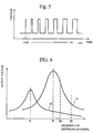
- the frequency control by the frequency switching controller 14 before the start of the electric discharge will be described hereinafter with reference to Figs. 5 to 7.
- the frequency switching controller 14 gives the oscillator 23 a command to start the electric discharge at a time t0
- the frequency of the pulse signal outputted from the oscillator 23 is decreased from a frequency fH toward a frequency f0 in accordance with a time constant corresponding to CR.
- the pulse width of the pulse signal outputted from the oscillator 23 is increased from zero toward a predetermined pulse width in accordance with another time constant corresponding to CR.
- an absolute value of the voltage peak across the discharge electrodes 13a and 13b is gradually increased as shown in Fig. 7(b).
- the first reason for this is that the frequency of the pulse signal is, at first, considerably higher than fH and gradually increased from the frequency fH to the frequency f0 with the lapse of time.
- the second reason for this is that the pulse width of the pulse signal is, at first, zero and gradually increased from zero toward the predetermined pulse width with the lapse of time. If the voltage peak across the discharge electrodes reaches a certain voltage peak level in the vicinity of the series resonant frequency f0 shown in Fig. 6, the electric discharge is started.
- the period from the output of the discharge starting command to the start of the electric discharge may be a period from 1 to 100 ms as shown in Fig. 7(c).
- the frequency and/or the pulse width of the pulse signal are regulated to control the electric discharge current flowing through the gap between the discharge electrodes 13a and 13b.
- the switching circuit 21 is constituted by the switching transistors 21a and 21b and the diodes 21c and 21d in the second embodiment, this is merely by way of example and, thus, the switching circuit 21 may be constituted by an inverter of the half bridge type disclosed in the foregoing Provisional Patent No. 61-22555, an inverter of the half-wave type disclosed in the foregoing Provisional Patent No. 62-40948, or a circuit adopting a reverse conducting thyristor as a switching element.
- the switching circuit 21 is separately excited in accordance with the pulse signal from the oscillator 23, this is also merely by way of example and, thus, the switching circuit 21 may be a self-excitation type circuit which is operated to self-determine a frequency for the switching.
- the switching transistors 21 and 21b are merely by way of example and may be replaced with Field Effect transistors (each generally referred to as "FET" for brevity).
- the boosting transformer 22 may be modified.
- the center tap 22c is eliminated from the boosting transformer 22, or the boosting transformer 22 may further comprise an auxiliary winding.
- the boosting transformed 22 is excluded from the electric discharge apparatus when the switching circuit 21 is capable of outputting a sufficient alternating voltage to cause an electric discharge in the gap between the discharge electrodes 13a and 13b.
- the oscillator 23 may be a free running multivibrator in which the frequency of the pulse signal is determined on the basis of the product of a resistance value multiplied by a capacitance value.
- the free running multivibrator comprises two capacitors having different capacitance values or two resistors having different resistance values.
- the frequency of the pulse signal of the free running multivibrator is varied by changing one of the resistors to the other of the resistors.
- the oscillator 23 may be a voltage controlled oscillator (generally referred to as "VCO" for brevity) in which the frequency of the pulse signal is varied by regulating a voltage of a control signal.
- VCO voltage controlled oscillator
- the output voltage of the switching circuit 21 is controlled by regulating the frequency of the pulse signal outputted from the oscillator 23, this is merely by way of example and, thus, the output voltage of the switching circuit 21 may be controlling by modulating the pulse width of the pulse signal of the switching circuit 21 through pulse width modulation techniques. In other words, a duty ratio of the pulse signal of the switching circuit 21 may be varied to control the output voltage of the switching circuit 21 and accordingly to control the electric discharge current. If the alternating voltage V2(f1) across the discharge electrodes 13a and 13b is still higher than the desired voltage level after the start of the electric discharge, not only the alternating voltage across the discharge electrodes 13a and 13b but also the electric discharge current is decreased by reducing the duty ratio of the pulse signal.
- the third embodiment of the electric discharge apparatus includes the same constitutional elements as the second embodiment of the electric discharge apparatus does.
- the constitutional elements of the third embodiment are respectively designated by the same reference numerals and symbols as the individual constitutional elements of the second embodiment are done, with intention of omitting repeated description thereof.
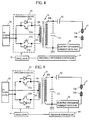
- the electric discharge apparatus is shown in Fig. 8 as comprising an electric discharge current detector 30 provided in a current carrying line connecting at its one end to the secondary winding 22b of the boosting transformer 22 and the discharge electrode 13b.
- the electric discharge current detector 30 is designed to detect an electric current flowing through the current carrying line between the secondary winding 22b of the boosting transformer 22 and the discharge electrode 13b and inform the frequency switching controller 14 of the detected electric current.
- the frequency switching controller 14 is adapted to compare an absolute value of the detected electric current with a predetermined value.
- the frequency switching controller 14 detects that the absolute value of the detected electric current exceeds the predetermined value, the frequency switching controller 14 considers that the electric discharge is started, and, subsequently starts to control the frequency of the pulse signal of the oscillator 23 to obtain a desired electric discharge current.
- the electric discharge current detector 14 comprises, for example, a resistor having a low resistance value and is operated to rectify and smooth a voltage across the resistor.
- the operation and control of the electric discharge apparatus are similar to those of the second embodiment according to the present invention except for the automatically detection of the electric discharge start.
- the fourth embodiment of the electric discharge apparatus includes the same constitutional elements as the third embodiment of the electric discharge apparatus does.
- the constitutional elements of the fourth embodiment are respectively designated by the same reference numerals and symbols as the individual constitutional elements of the third embodiment are done, with the intention of omitting repeated description thereof.
- the electric discharge apparatus is shown in Fig. 9 as including a feedback controller 40 provided instead of the frequency switching controller 14 shown in Fig.8.
- the feedback controller 40 is designed to monitor the electric discharge current based on the output of the electric discharge current detector 30 to self-correct or control the electric discharge current, thereby making it possible to adjust the electric discharge current to a desired level.
- the frequency of the pulse signal of the oscillator 23 is set to the series resonant frequency f1 or to a frequency in the vicinity of the series resonant frequency f1 by the feedback controller 40. While the electric discharge is continued, the frequency or pulse width of the pulse signal of the oscillator 23 is controlled by the feedback controller 40 to adjust the discharge current to the desired level.
- the frequency of the pulse signal is decreased toward the series resonant frequency f2 by the feedback controller 40.
- the decrement of the frequency of the pulse signal means that the output voltage of the switching circuit 21 is increased and, accordingly, the electric discharge current is increased and approaches the predetermined current level. If the electric discharge current exceeds the predetermined current level, the frequency of the pulse signal of the oscillator 23 is controlled by the feedback controller 40 to increase.
- the increment of the frequency of the pulse signal means that the output voltage of the switching circuit 21 is decreased and, consequently, the electric discharge current is held at the predetermined current level.
- the frequency or the pulse width of the pulse signal is decreased by the feedback controller 40.
- the decrement of the frequency or pulse width results in the fact that an energy supplied to the secondary winding 22b of the boosting transformer 22 becomes smaller and, for this reason, the electric discharge current is reduced, thereby making it possible to cause the electric discharge current to approach the predetermined current level.
- the pulse width of the pulse signal is increased by the feedback controller 40.
- the increment of the pulse width of the pulse signal results in the fact that the energy supplied to the secondary winding 22b of the boosting transformer 22 is increased and, as a consequence, the electric discharge current is held at the predetermined current level.
- the pulse width of the pulse signal immediately after and before the start of the electric discharge is preferably adjusted approximately to the largest value, i.e., the duty ratio of the pulse signal is preferably adjusted approximately to 50%.
- the feedback controller 40 enables the electric discharge apparatus to carry out the feedback control based on the regulation of the frequency and/or pulse width of the pulse signal of the oscillator 23. This means that not only the frequency of the alternating voltage across the discharge electrodes 13a and 13b can be set to a desired frequency level, but also the electric discharge current can be automatically held at the predetermined current level.
- the electric discharge apparatus may further comprise a voltage detector for detecting the output voltage of the DC power supply 20.
- the feedback controller 40 is operated to increase the pulse width of the pulse signal of the oscillator 23 toward the largest level in accordance with the decrement of the output voltage of the DC power supply 20.
- the way to eliminate the drawback may be applied to other embodiments of the electric discharge apparatuses each include a battery as DC power supply.
- the discharge current regulation or feedback control techniques in the foregoing embodiment according to the present invention may be applied to the prior-art electric discharge apparatus shown in Figs. 16 and 17. Since the apparatus shown in Fig. 16 comprises a circuit corresponding to an alternating voltage generator having a series resonant frequency, the circuit is operated with a resonant characteristic similar to that represented by the curve C2 in Fig. 2 after the start of the electric discharge. Therefore, the foregoing electric discharge current regulation or feedback control is performed by controlling the frequency and pulse width of the pulse signal supplied to the base terminals of the switching transistors 106 and 107 shown in Fig. 16. In this case, the frequency of the pulse signal may be set to the series resonant frequency of the circuit shown in Fig. 16 or to a frequency in the vicinity of the series resonant frequency.
- the fifth embodiment of the electric discharge apparatus includes the same constitutional elements as the first embodiment of the electric discharge apparatus dose.
- the constitutional elements of the fifth embodiment are respectively designated by the same reference numerals and symbols as the individual constitutional elements of the first embodiment are done, with the intention of omitting repeated description thereof.
- the electric discharge apparatus is shown in Fig. 10 as comprising a clamp circuit 50 for clamping the alternating voltage generated by the alternating voltage generator 11 in cooperation with the capacitor 12 while the alternating voltage is applied to the discharge electrodes 13a and 13b through the capacitor 12.
- the clamp circuit 50 is an unilateral circuit connected to the capacitor 12 in series and connected to the discharge electrode unit 13 in parallel. More specifically, the clamp circuit 50 is illustrated as comprising a diode 50a and a resistor 50b connected to each other in series. Note that the resistor 50b may be a current-limiting resistor having a relatively large resistance value.
- the capacitor 12 may has a capacitance value set within 20 - 100 pF.
- the series resonant frequency f1 may be set within 10 - 300 kHz.
- the resistor 50b may has a resistance value set within 10 k ⁇ - 100 M ⁇ .
- the capacitance value of the capacitor 12, the series resonant frequency f1, and the resistance value of the resistor 50b may be set to 60 pF, 60 kHz, and 1 M ⁇ , respectively.
- a load bored by the AC power supply 11a is considered to be a series connection circuit of the inductance element 11b and the capacitance element 11c.
- the frequency of the alternating voltage of the AC power supply 11a is set to the series resonant frequency f1 and to a frequency in the vicinity of the series resonant frequency f1.
- the alternating voltage is supplied from the AC power supply 11a to the series connection circuit of the inductance element 11b and the capacitance element 11c and, accordingly, a high series resonant voltage is generated at the output terminals of the alternating voltage generator 11.
- the series connection circuit of the diode 50a and resistor 50b allows a few electric current to flow through the capacitor 12 and, as a result, has the capacitor 12 charged.
- the series connection circuit of the diode 50a and the resistor 50b prevents the electric current from flowing through the capacitor 12.
- the series resonant voltage generated at the output terminals of the alternating voltage generator 11 is added to the voltage across the charged capacitor 12 and then applied to the discharge electrodes 13a and 13b.
- the voltage across the discharge electrodes 13a and 13b is varied in the form of sinuous wave with the lapse of time as shown in Fig. 11(a).
- the lower voltage peaks of the voltage across the discharge electrodes 13a and 13b are clamped approximately at a zero voltage level.
- the upper voltage peaks of the voltage across the discharge electrodes 13a and 13b are gradually increased.
- the electric discharge between the discharge electrodes 13a and 13b is caused to start. As a result, the electric discharge current starts to flow through the gap between the discharge electrodes 13a and 13b as shown in Fig. 11(b).
- the discharge electrode unit 13 serves as a low impedance state load.
- the capacitance element llc and the capacitor 12 are considered to be a parallel connection circuit. Since the resistance value of the resistor 50b is relatively large, the resistor 50b has no influence upon the parallel connection circuit of the capacitance element 11c and the capacitor 12.
- the AC power supply 11a therefore, bears a load comprising the inductance element 11b and the parallel connection circuit of the capacitance element 11c and the capacitor 12.
- the electric discharge apparatus shown in Fig. 10 has a series resonant frequency characteristic similar to that represented by the curve C2 shown in Fig. 2 and, for this reason, the output voltage of the alternating voltage generator 11 can reach the voltage peak V2(f2) at the series resonant frequency f2 as shown in Fig. 2.
- the resonant voltage shown in Fig. 11(a) has upper voltage peaks which are respectively twice as large as those shown in Fig. 3(a). Even if the AC power supply lla has a small output voltage in comparison with that of the first embodiment, the electric discharge apparatus can start the electric discharge. It is assumed that the alternating voltage generator 11 comprises a DC power supply and a switching circuit. Even if the DC power supply has a small output voltage in comparison with that of the second embodiment, the electric discharge apparatus can start the electric discharge. It is, in addition, assumed that the alternating voltage generator 11 comprises a boosting transformer. Even if the boosting transformer has a small boosting ratio in comparison with that of the second embodiment, the electric discharge apparatus can start the electric discharge. Therefore, the electric discharge apparatus can be simplified in construction.
- the clamp circuit 50 includes only one diode in this embodiment, the clamp circuit 50 may includes a plurality of diodes connected in series. The series connection of diodes enables the clamp circuit 50 to withstand the high voltage. If, however, desired, the clamp circuit 50 may includes no diode.
- the clamp circuit 50 may be an unilateral circuit which comprises not the diode but an unilateral element allowing an electric current to flow in a forward direction and preventing the electric current from flowing in a backward direction.
- the unilateral circuit may comprise a complex circuit including the unilateral element.
- the clamp circuit 50 shown in Fig. 10 is a positive clamper as appreciated from Fig. 11(a)
- the clamp circuit 50 may be a negative clamper having the diode 50a reversed and connected to the resistor 50b.
- the clamp circuit 50 may be a base clamper or a peak clamper including a bias power supply connected to the diode 50a in series.
- the clamp circuit 50 may be any circuit, provided the circuit causes the electric discharge in the gap between the discharge electrodes 13a and 13b by adding DC components to a wave form having no DC component, and further provided the circuit is capable of starting the electric discharge with stability.
- the clamp circuit 50 may further comprise a switching unit connected to the resistor 50b in parallel.
- the switching unit assumes two different switching positions consisting of a first switching position in which both ends of the resistor 50b are short-circuited to disable the resistor 50b, and a second switching position in which the short circuit of the both ends of the resistor 50b is canceled to enable the resistor 50b.
- the sixth embodiment of the electric discharge apparatus includes the same constitutional elements as the first embodiment of the electric discharge apparatus does.
- the constitutional elements of the sixth embodiment are respectively designated by the same the reference numerals and symbols as the individual constitutional elements of the first embodiment are done, with the intention of omitting repeated description thereof.
- the electric discharge apparatus is shown in Fig. 12 as comprising a resistor 60 connected in parallel to and bypassing the capacitor 12.
- the resistor 60 has a resistance value incomparably larger than a reactance value of the capacitor 12.
- the capacitor 12 and the resistor 60 as a whole form a parallel connection circuit 61.
- the capacitor 12 may has a capacitance value set within 20 - 100 pF and the series resonant frequency f1 may be set within 10 - 300kHz.
- the resistor 60 may has a resistance value set within 10 k ⁇ - 100 M ⁇ .
- the capacitance value of the capacitor 12, the series resonant frequency f1, and the resistance value of the resistor 60 may be set to 60 pF, 60 kHz, and 1 M ⁇ , respectively.
- the AC power supply 11a bears a load which is considered to be a series connection circuit of the inductance element 11b and the capacitance element 11c before the start of the electric discharge because of the fact that the discharge electrode unit 13 is held in the high impedance state and that the resistance value of the resistor 60 is extremely large.
- the frequency of the alternating voltage of the AC power supply 11a is set to the series resonant frequency f1 or to a frequency in the vicinity of the series resonant frequency f1.
- the alternating voltage is supplied from the AC power supply 11a to the series connection circuit of the inductance element 11b and the capacitance element 11c and, accordingly, a high series resonant voltage is generated at the output terminals of the alternating voltage generator 11.
- the resonant voltage is divided into two voltages, one of the voltages being applied to the parallel connection circuit 61 and the other of the voltages being applied to the discharge electrode unit 13.
- the voltage across the discharge electrode unit 13 is varied in the form of a sinuous curve and, accordingly, has an absolute voltage peak level gradually increased with the lapse of time as shown Fig. 3(a).
- the electric discharge between the discharge electrodes 13a and 13b is started.
- the electric discharge current flows through the gap between the discharge electrodes 13a and 13b as shown in Fig. 3(b).
- the discharge electrode unit 13 serves as a low impedance load.
- the capacitance element 11c and the capacitor 12 are considered to be a parallel connection circuit. Since the resistance value of the resistor 60 is extremely large, the resistor 60 has little influence upon the parallel connection circuit of the capacitance element 11c and the capacitor 12.
- the AC power supply 11a therefore, bears a load comprising the inductance element 11b and the parallel connection circuit of the capacitance element 11c and the capacitor 12.
- the electric discharge apparatus shown in Fig. 12 has a series resonant characteristic similar to that represented by the curve C2 shown in Fig. 2 and, for this reason, the voltage across the discharge electrodes 13a and 13b can reach a voltage peak at the series resonant frequency f2.
- the resistor 60 is connected in parallel to and bypasses the capacitor 12 and accordingly results in the following advantages. Even if the AC power supply 11a has a small output voltage in comparison with that of the first embodiment, the electric discharge apparatus can start the electric discharge. It is assumed that the alternating voltage generator 11 comprises a DC power supply and a switching circuit. Even if the DC power supply has a small output voltage in comparison with that of the second embodiment, the electric discharge apparatus can start the electric discharge. It is, in addition, assumed that the alternating voltage generator 11 comprises a boosting transformer. Even if the boosting transformer has a small boosting ratio in comparison with that of the second embodiment, the electric discharge apparatus can start the electric discharge.
- the electric discharge apparatus can be simplified in construction. Since the resistor 60 has the relatively large resistance value, the resistor 60 has little undesired influence upon the electric discharge apparatus during the electric discharge. If, however, desired, the resistor 60 is disconnected from the capacitor 2 after the electric discharge is started.
- the seventh embodiment of the electric discharge apparatus includes the same constitutional elements as the fourth embodiment of the electric discharge apparatus does.
- the constitutional elements of the seventh embodiment are respectively designated by the same reference numerals and symbols as the individual constitutional elements of the fourth embodiment are done, with the intention of omitting repeated description thereof.
- the electric discharge apparatus is shown in Fig. 13 as comprising a resistance unit 70 interposed between the electric discharge current detector 30 and the discharge electrode 13b and connected to the discharge electrode unit 13 in series.
- the resistance unit 70 has a variable resistance value.
- the feedback controller 40 is operated to regulate the resistance value of the resistance unit 70 to control the electric discharge current.
- the resistance unit 70 comprises, for example, a resistor connected the discharge electrode unit 13 in series, and a switch connected to the resistor in parallel.
- the switch assumes two different switching positions consisting of a first switching position in which both ends of the resistor are short-circuited to disable the resistor, and a second switching position in which the short circuit of the both ends of the resistor is canceled to enable the resistor.
- the electric discharge apparatus thus constructed is intended to stabilize the electric discharge current to an arbitrary value variable throughout a wide current range.
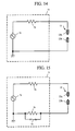
- Fig. 14 shows a simple electric discharge circuit comprising an alternating voltage generator 71 in addition to the discharge electrode unit 13.
- the alternating voltage generator 71 comprises an AC power supply 72 generating an alternating voltage and a current-limiting resistor 73 interposed between the AC power supply 72 and the discharge electrode 13a.
- the output voltage of the AC power supply 72 is applied to the discharge electrode unit 13 through the current-limiting resistor 73 as well as through internal resistance of the AC power supply 72 and so on.
- the internal resistance has an impedance varied imperceptibly.
- the alternating voltage generator 71 has an internal impedance that is varied within a narrow impedance range.
- the output voltage of the alternating voltage generator 71 is varied within a narrow voltage range depending upon the foregoing narrow impedance range and, as a consequence, the electric discharge current is variable only within a narrow current range based on the narrow voltage range.
- the electric discharge current is controlled by regulating the output voltage of the AC power supply. The AC power supply is, therefore, required to reduce its output voltage in order to decrease the electric discharge current. If, however, the output voltage is decreased approximately to a voltage for the maintenance of the electric discharge, the electric discharge is unsteadied and, at the worst, stopped.
- the electric discharge current is required to be regulated under the condition that the output voltage of the AC power supply is sufficiently higher than an electric discharge maintenance voltage, or a voltage for the maintenance of the electric discharge.
- the variation of the internal impedance is within the narrow impedance range, so that the electric discharge current cannot be regulated within a wide current range.
- the internal impedance is required to be increased in order to decrease the electric discharge current. The increment of the internal impedance, however, results in the fact that the apparatus has a large power loss and, for this reason, works with low efficiency.
- Fig. 15 shows an electric discharge apparatus constructed in view of the forgoing drawbacks of the circuit shown in Fig. 14.
- the electric discharge apparatus shown in Fig. 15 further comprises a resistor 74 interposed between the AC power supply 72 and the discharge electrode 13b, and a switch 75 connected to the resistor 74 in parallel. More specifically, the resistor 74 and the switch 75 are connected to the lower voltage side electrode 13b of the discharge electrode unit 13.
- the switch 75 is adapted to assume two different switching positions consisting of a first switching position in which both ends of the resistor 74 are short-circuited to disable the resistor 74, and a second switching position in which the short circuit of the both ends of the resistor 74 is canceled to enable the resistor 74.
- the first switching position means that the switch 74 is in the "ON” condition, while the second switching position means that the switch 74 is in the "OFF” condition.
- the switch 74 may be a manual switch, the switch 74 may be, preferably, a field effect transistor switch which is of a photo-coupler type capable of insulating the circuit from a controller.
- the internal impedance of the circuit form the view of the discharge electrode unit 13 is reduced, so that the circuit enables the large discharge current to flow through the discharge electrode unit 13, thereby making it possible to cause the circuit to work with efficiency.
- the impedance range throughout which the internal impedance from the view of the discharge electrode unit 13 is variable can varied in accordance with the operation of the switch 75. Therefore, the current range throughout which the electric discharge current is controllably variable is increased with efficiency.
- Vout is indicative of the output voltage of the AC power supply 72
- R is indicative of the resistance value of the current-limiting resistor 71
- r g is indicative of an impedance between the discharge electrodes 13a and 13b at a time when the electric discharge held in a constant state.
- the electric discharge circuit allows an electric discharge current I' to flow therethrough.
- the latter electric discharge current I' is larger than the former electric discharge current I under the same output voltage Vout. If the electric discharge current decreased to a small level is intended to be restored to a large level, the intention is accomplished by decreasing the output voltage Vout of the AC power supply 72.
- the circuit comprises a current detector detecting the electric discharge current to carry out a feedback control under which the electric discharge current is held at a constant level, the output voltage Vout is increased to such an extent that the latter electric discharge current I' is equal to the former electric discharge current I.
- the output voltage of the alternating voltage generator 71 is held at a level which is sufficiently larger than the electric discharge maintenance voltage. Accordingly, the electric discharge can be stabilized even if a small electric discharge current is intended to flow through the circuit.
- the circuit causes a small discharge current to flow therethrough with stability by increasing the internal impedance of the circuit from the view of the discharge electrode unit 13, thereby making it possible to enlarge a current range throughout which the electric discharge current to be set for a desired electric discharge is variable.
- the alternating voltage generator 71 includes only one resistor 74 except the current-limiting resistor 73, the alternating voltage generator 71 may includes a plurality of resistors collectively forming a resistance unit and respectively having resistance values different from one another. In the resistance unit, one of the resistors is selected and connected to the circuit, so that the resistance unit has a resistance value variable depending upon the selection of the resistors.
- the circuit may include a variable resistor instead of the resistance 74 and the switch 75. When the resistance unit or the variable resistor is adopted, the apparatus is operated to regulate the resistance value of the resistance unit or the variable resistor to perform the feedback control for the electric discharge current.
- the resistance unit 70 is constituted for example by the parallel connection circuit of the resistor 74 and the switch 75 shown in Fig. 15, or other variable resistance units each having a variable resistance value. Although a resistance element corresponding to the current-limiting resistor 73 is not shown in Fig. 13, the resistance element may be included in the resistance unit 70.
- the reason why the resistance unit 70 is provided on a lower potential line between the discharge current detector 30 and the discharge electrode 13b is that the discharge current detector 30 is connected to a grounded line.
- the resistance value of the resistance unit 70 is held at a low level by the feedback controller 40.
- the pulse width or duty ratio of the pulse signal of the oscillator 23 is reduced and, at the same time, the resistance value of the resistance unit 70 is controlled to increase. This means that the internal impedance is increased and, accordingly that electric discharge current is decreased to approach the desired level.
- the pulse width or the duty ratio of the pulse signal of the oscillator 23 is increased. This results in the fact that output voltage of the secondary winding 22b of the boosting transformer 22 is increased and, for this reason, the electric discharge current is held at the desired level.
- the feedback controller 40 may be operated to control the frequency of the pulse signal of the oscillator 23.
- the apparatus further may comprise detecting means for detecting an output voltage of the DC power supply 20. If the detecting means detects that the output voltage is decreased, the resistance value of the resistance unit 70 is manually or automatically controlled to decrease.
- the way to vary the internal impedance of the electric discharge circuit can be applied to the apparatus shown in Fig. 16 or other electric discharge apparatuses each employing a DC high voltage source.
Landscapes
- Physics & Mathematics (AREA)
- Engineering & Computer Science (AREA)
- Optics & Photonics (AREA)
- Plasma & Fusion (AREA)
- Chemical & Material Sciences (AREA)
- Combustion & Propulsion (AREA)
- Mechanical Engineering (AREA)
- General Engineering & Computer Science (AREA)
- General Physics & Mathematics (AREA)
- Generation Of Surge Voltage And Current (AREA)
- Lasers (AREA)
Applications Claiming Priority (8)
| Application Number | Priority Date | Filing Date | Title |
|---|---|---|---|
| JP23654995 | 1995-09-14 | ||
| JP236547/95 | 1995-09-14 | ||
| JP236549/95 | 1995-09-14 | ||
| JP236546/95 | 1995-09-14 | ||
| JP236548/95 | 1995-09-14 | ||
| JP23654695 | 1995-09-14 | ||
| JP23654895 | 1995-09-14 | ||
| JP23654795 | 1995-09-14 |
Publications (2)
| Publication Number | Publication Date |
|---|---|
| EP0763759A2 true EP0763759A2 (fr) | 1997-03-19 |
| EP0763759A3 EP0763759A3 (fr) | 1997-09-17 |
Family
ID=27477669
Family Applications (1)
| Application Number | Title | Priority Date | Filing Date |
|---|---|---|---|
| EP96306035A Withdrawn EP0763759A3 (fr) | 1995-09-14 | 1996-08-19 | Méthode et appareil de décharge électrique |
Country Status (3)
| Country | Link |
|---|---|
| US (1) | US5777867A (fr) |
| EP (1) | EP0763759A3 (fr) |
| CA (1) | CA2183840C (fr) |
Cited By (6)
| Publication number | Priority date | Publication date | Assignee | Title |
|---|---|---|---|---|
| FR2917565A1 (fr) * | 2007-06-12 | 2008-12-19 | Renault Sas | Dispositif de mesure dans un systeme d'allumage radiofrequence pour un moteur a combustion interne |
| EP2012004A1 (fr) * | 2007-07-03 | 2009-01-07 | Delphi Technologies, Inc. | Dispositif d'allumage à haute fréquence et son procédé de fonctionnement |
| EP2141352A1 (fr) * | 2008-07-02 | 2010-01-06 | Delphi Technologies, Inc. | Système d'ignition |
| EP2554832A1 (fr) * | 2011-08-04 | 2013-02-06 | NEQLab Holding Inc. | Procédé d'allumage, bougie d'allumage et moteur utilisant la bougie d'allumage |
| FR2982647A1 (fr) * | 2011-11-16 | 2013-05-17 | Continental Automotive France | Dispositif et procede d'allumage continu |
| WO2023156457A1 (fr) * | 2022-02-15 | 2023-08-24 | Woco Gmbh & Co. Kg | Circuit de commande pour un électrofiltre |
Families Citing this family (16)
| Publication number | Priority date | Publication date | Assignee | Title |
|---|---|---|---|---|
| US5968398A (en) * | 1997-05-16 | 1999-10-19 | The Lepel Corporation | Apparatus and method for non-contact detection and inductive heating of heat retentive food server warming plates |
| WO2001084678A2 (fr) * | 2000-04-18 | 2001-11-08 | Lambda Physik Ag | Technique de stabilisation pour lasers gazeux a haute frequence de repetition d"impulsions |
| AU782604B2 (en) * | 2001-05-22 | 2005-08-11 | Sumitomo Electric Industries, Ltd. | Method for fusion splicing optical fibers and apparatus for heating spliced part by arc |
| JP2005063819A (ja) * | 2003-08-13 | 2005-03-10 | Koito Mfg Co Ltd | 放電灯点灯回路 |
| US7737382B2 (en) * | 2004-04-01 | 2010-06-15 | Lincoln Global, Inc. | Device for processing welding wire |
| JP4684765B2 (ja) * | 2005-06-29 | 2011-05-18 | 日本碍子株式会社 | 電気回路及びパルス電源 |
| US7221100B2 (en) * | 2005-08-12 | 2007-05-22 | Alameda Applied Sciences Corp. | Gas discharge lamp power supply |
| US7985029B2 (en) | 2007-02-07 | 2011-07-26 | 3Sae Technologies, Inc. | Multi-electrode system with vibrating electrodes |
| US7643267B2 (en) * | 2007-03-15 | 2010-01-05 | Shimadzu Corporation | Optical emission spectrometry device |
| JP2009185690A (ja) * | 2008-02-06 | 2009-08-20 | Honda Motor Co Ltd | 内燃機関用トランジスタ式点火装置 |
| US9072169B1 (en) * | 2010-07-13 | 2015-06-30 | Cascodium Inc. | Pulse generator and systems and methods for using same |
| US9709017B2 (en) | 2013-06-04 | 2017-07-18 | Mitsubishi Electric Corporation | Ignition device of spark-ignition internal combustion engine |
| CN105545564B (zh) * | 2016-01-29 | 2018-06-29 | 郑明� | 多极高频放电的弹性击穿点火系统和方法 |
| DE102016003793A1 (de) * | 2016-03-29 | 2017-10-05 | Rosenberger Hochfrequenztechnik Gmbh & Co. Kg | Zündvorrichtung zum Zünden eines Luft-Kraftstoffgemisches in einem Brennraum |
| US10648442B2 (en) * | 2018-10-15 | 2020-05-12 | Semiconductor Components Industries, Llc | Circuit and method for coil current control |
| WO2020115899A1 (fr) * | 2018-12-07 | 2020-06-11 | 三菱電機株式会社 | Système d'allumage |
Citations (6)
| Publication number | Priority date | Publication date | Assignee | Title |
|---|---|---|---|---|
| GB2085678A (en) * | 1980-10-15 | 1982-04-28 | Nippon Telegraph & Telephone | Method of fusion-splicing optical fibres |
| US4358712A (en) * | 1980-12-29 | 1982-11-09 | Altex Scientific, Inc. | Discharge lamp ballast |
| US4538093A (en) * | 1981-05-14 | 1985-08-27 | U.S. Philips Corporation | Variable frequency start circuit for discharge lamp with preheatable electrodes |
| US4758386A (en) * | 1987-01-15 | 1988-07-19 | Itt | Wave-shaped AC arc for lensing system |
| US4904905A (en) * | 1988-08-05 | 1990-02-27 | American Sterilizer Company | Dual resonant frequency arc lamp power supply |
| US5083065A (en) * | 1989-10-23 | 1992-01-21 | Nissan Motor Co., Ltd. | Lighting device for electric discharge lamp |
Family Cites Families (13)
| Publication number | Priority date | Publication date | Assignee | Title |
|---|---|---|---|---|
| GB1571884A (en) * | 1975-12-03 | 1980-07-23 | Lucas Industries Ltd | Spark ignition systems for gas turbine engines |
| DE3608615A1 (de) * | 1986-03-14 | 1987-09-17 | Patent Treuhand Ges Fuer Elektrische Gluehlampen Mbh | Schaltungsanordnung zum betrieb von niederdruckentladungslampen |
| US4658343A (en) * | 1986-04-03 | 1987-04-14 | Shepard Jr Francis H | Fluorescent lamp driver |
| JPH07111918B2 (ja) * | 1987-07-28 | 1995-11-29 | 三菱電機株式会社 | マイクロ波放電光源装置 |
| US5019749A (en) * | 1988-05-10 | 1991-05-28 | Seiko Epson Corporation | Back-light device for a video display apparatus |
| FR2649759B1 (fr) * | 1989-07-13 | 1994-06-10 | Siemens Bendix Automotive Elec | Dispositif d'allumage pour moteur a combustion interne |
| US5117088A (en) * | 1991-03-13 | 1992-05-26 | The Lincoln Electric Company | Device and method for starting electric arc of a welder |
| US5165003A (en) * | 1991-06-28 | 1992-11-17 | Sumitomo Electric Fiber Optics Corp. | Optical fiber cable including interlocking stitch binder |
| JPH06141552A (ja) * | 1992-10-26 | 1994-05-20 | Kasuga Denki Kk | 高周波高圧電源の電力制御装置 |
| GB2275140B (en) * | 1993-02-13 | 1997-06-18 | Kijima Co Ltd | Push-pull inverter |
| JP2733817B2 (ja) * | 1993-08-30 | 1998-03-30 | 昌和 牛嶋 | 放電管用インバーター回路 |
| JP3547837B2 (ja) * | 1995-03-31 | 2004-07-28 | ミネベア株式会社 | インバ−タ装置 |
| US5619402A (en) * | 1996-04-16 | 1997-04-08 | O2 Micro, Inc. | Higher-efficiency cold-cathode fluorescent lamp power supply |
-
1996
- 1996-08-07 US US08/694,494 patent/US5777867A/en not_active Expired - Lifetime
- 1996-08-19 EP EP96306035A patent/EP0763759A3/fr not_active Withdrawn
- 1996-08-21 CA CA002183840A patent/CA2183840C/fr not_active Expired - Lifetime
Patent Citations (6)
| Publication number | Priority date | Publication date | Assignee | Title |
|---|---|---|---|---|
| GB2085678A (en) * | 1980-10-15 | 1982-04-28 | Nippon Telegraph & Telephone | Method of fusion-splicing optical fibres |
| US4358712A (en) * | 1980-12-29 | 1982-11-09 | Altex Scientific, Inc. | Discharge lamp ballast |
| US4538093A (en) * | 1981-05-14 | 1985-08-27 | U.S. Philips Corporation | Variable frequency start circuit for discharge lamp with preheatable electrodes |
| US4758386A (en) * | 1987-01-15 | 1988-07-19 | Itt | Wave-shaped AC arc for lensing system |
| US4904905A (en) * | 1988-08-05 | 1990-02-27 | American Sterilizer Company | Dual resonant frequency arc lamp power supply |
| US5083065A (en) * | 1989-10-23 | 1992-01-21 | Nissan Motor Co., Ltd. | Lighting device for electric discharge lamp |
Cited By (8)
| Publication number | Priority date | Publication date | Assignee | Title |
|---|---|---|---|---|
| FR2917565A1 (fr) * | 2007-06-12 | 2008-12-19 | Renault Sas | Dispositif de mesure dans un systeme d'allumage radiofrequence pour un moteur a combustion interne |
| WO2008155496A1 (fr) * | 2007-06-12 | 2008-12-24 | Renault S.A.S. | Dispositif de mesure dans un systeme d'allumage radiofrequence pour un moteur a combustion interne |
| US8387446B2 (en) | 2007-06-12 | 2013-03-05 | Renault S.A.S. | Measuring device in a radiofrequency ignition system for internal combustion engine |
| EP2012004A1 (fr) * | 2007-07-03 | 2009-01-07 | Delphi Technologies, Inc. | Dispositif d'allumage à haute fréquence et son procédé de fonctionnement |
| EP2141352A1 (fr) * | 2008-07-02 | 2010-01-06 | Delphi Technologies, Inc. | Système d'ignition |
| EP2554832A1 (fr) * | 2011-08-04 | 2013-02-06 | NEQLab Holding Inc. | Procédé d'allumage, bougie d'allumage et moteur utilisant la bougie d'allumage |
| FR2982647A1 (fr) * | 2011-11-16 | 2013-05-17 | Continental Automotive France | Dispositif et procede d'allumage continu |
| WO2023156457A1 (fr) * | 2022-02-15 | 2023-08-24 | Woco Gmbh & Co. Kg | Circuit de commande pour un électrofiltre |
Also Published As
| Publication number | Publication date |
|---|---|
| CA2183840A1 (fr) | 1997-03-15 |
| CA2183840C (fr) | 2001-01-09 |
| US5777867A (en) | 1998-07-07 |
| EP0763759A3 (fr) | 1997-09-17 |
Similar Documents
| Publication | Publication Date | Title |
|---|---|---|
| US5777867A (en) | Electric discharge method and apparatus | |
| US5438242A (en) | Apparatus for controlling the brightness of a magnetron-excited lamp | |
| US5629844A (en) | High voltage power supply having multiple high voltage generators | |
| US5671128A (en) | Power supply apparatus | |
| JP3119822B2 (ja) | 放電電流供給方法および放電電流供給装置 | |
| US4511195A (en) | Device for starting and operating gas discharge tubes | |
| US6291945B1 (en) | Discharge lamp lighting device | |
| EP0641066B1 (fr) | Circuit d'alimentation en courant avec un push-pull-convertisseur résonant | |
| US5428633A (en) | He-Ne laser driving power supply with means for interrupting feedback control at driving start of the laser | |
| EP1324299A2 (fr) | Dispositif et méthode pour l'injection ou pour la décharge de l'énergie dans ou d'un panneau d'affichage plasma | |
| GB2147162A (en) | Gas discharge lamp control circuits for absorbance monitors | |
| US11764666B2 (en) | DC pulse power supply device and frequency control method for DC pulse power supply device | |
| JPH04115168A (ja) | 電流検出回路 | |
| JP4949285B2 (ja) | プラズマ放電装置 | |
| JP3981208B2 (ja) | アーク加工用電源装置 | |
| JP3858831B2 (ja) | レーザ発振装置とレーザ加工機 | |
| JP3587998B2 (ja) | 電源装置 | |
| JP2643163B2 (ja) | 電源装置 | |
| JP3596372B2 (ja) | 電源装置 | |
| JP3328784B2 (ja) | 交流放電灯点灯装置および直流放電灯点灯装置 | |
| JP3260776B2 (ja) | 画像形成装置の電源回路 | |
| JPH0297227A (ja) | 電源装置 | |
| JPH01197998A (ja) | インバータ式x線装置 | |
| JP3886608B2 (ja) | 直流アーク溶接用電源装置 | |
| KR100331442B1 (ko) | 공진형인버터식x선고전압장치 |
Legal Events
| Date | Code | Title | Description |
|---|---|---|---|
| PUAI | Public reference made under article 153(3) epc to a published international application that has entered the european phase |
Free format text: ORIGINAL CODE: 0009012 |
|
| AK | Designated contracting states |
Kind code of ref document: A2 Designated state(s): DE GB SE |
|
| PUAL | Search report despatched |
Free format text: ORIGINAL CODE: 0009013 |
|
| AK | Designated contracting states |
Kind code of ref document: A3 Designated state(s): DE GB SE |
|
| RAP1 | Party data changed (applicant data changed or rights of an application transferred) |
Owner name: SUMIDEN OPCOM, LTD. Owner name: SUMITOMO ELECTRIC INDUSTRIES LTD |
|
| 17P | Request for examination filed |
Effective date: 19971107 |
|
| 17Q | First examination report despatched |
Effective date: 20031031 |
|
| STAA | Information on the status of an ep patent application or granted ep patent |
Free format text: STATUS: THE APPLICATION IS DEEMED TO BE WITHDRAWN |
|
| 18D | Application deemed to be withdrawn |
Effective date: 20060301 |