EP2554832A1 - Procédé d'allumage, bougie d'allumage et moteur utilisant la bougie d'allumage - Google Patents
Procédé d'allumage, bougie d'allumage et moteur utilisant la bougie d'allumage Download PDFInfo
- Publication number
- EP2554832A1 EP2554832A1 EP11176514A EP11176514A EP2554832A1 EP 2554832 A1 EP2554832 A1 EP 2554832A1 EP 11176514 A EP11176514 A EP 11176514A EP 11176514 A EP11176514 A EP 11176514A EP 2554832 A1 EP2554832 A1 EP 2554832A1
- Authority
- EP
- European Patent Office
- Prior art keywords
- discharge
- ignition system
- plug
- discharge gap
- ignition
- Prior art date
- Legal status (The legal status is an assumption and is not a legal conclusion. Google has not performed a legal analysis and makes no representation as to the accuracy of the status listed.)
- Withdrawn
Links
Images


Classifications
-
- F—MECHANICAL ENGINEERING; LIGHTING; HEATING; WEAPONS; BLASTING
- F02—COMBUSTION ENGINES; HOT-GAS OR COMBUSTION-PRODUCT ENGINE PLANTS
- F02P—IGNITION, OTHER THAN COMPRESSION IGNITION, FOR INTERNAL-COMBUSTION ENGINES; TESTING OF IGNITION TIMING IN COMPRESSION-IGNITION ENGINES
- F02P15/00—Electric spark ignition having characteristics not provided for in, or of interest apart from, groups F02P1/00 - F02P13/00 and combined with layout of ignition circuits
- F02P15/08—Electric spark ignition having characteristics not provided for in, or of interest apart from, groups F02P1/00 - F02P13/00 and combined with layout of ignition circuits having multiple-spark ignition, i.e. ignition occurring simultaneously at different places in one engine cylinder or in two or more separate engine cylinders
-
- F—MECHANICAL ENGINEERING; LIGHTING; HEATING; WEAPONS; BLASTING
- F02—COMBUSTION ENGINES; HOT-GAS OR COMBUSTION-PRODUCT ENGINE PLANTS
- F02D—CONTROLLING COMBUSTION ENGINES
- F02D41/00—Electrical control of supply of combustible mixture or its constituents
- F02D41/30—Controlling fuel injection
- F02D41/3011—Controlling fuel injection according to or using specific or several modes of combustion
- F02D41/3017—Controlling fuel injection according to or using specific or several modes of combustion characterised by the mode(s) being used
- F02D41/3035—Controlling fuel injection according to or using specific or several modes of combustion characterised by the mode(s) being used a mode being the premixed charge compression-ignition mode
-
- F—MECHANICAL ENGINEERING; LIGHTING; HEATING; WEAPONS; BLASTING
- F02—COMBUSTION ENGINES; HOT-GAS OR COMBUSTION-PRODUCT ENGINE PLANTS
- F02P—IGNITION, OTHER THAN COMPRESSION IGNITION, FOR INTERNAL-COMBUSTION ENGINES; TESTING OF IGNITION TIMING IN COMPRESSION-IGNITION ENGINES
- F02P15/00—Electric spark ignition having characteristics not provided for in, or of interest apart from, groups F02P1/00 - F02P13/00 and combined with layout of ignition circuits
- F02P15/10—Electric spark ignition having characteristics not provided for in, or of interest apart from, groups F02P1/00 - F02P13/00 and combined with layout of ignition circuits having continuous electric sparks
-
- F—MECHANICAL ENGINEERING; LIGHTING; HEATING; WEAPONS; BLASTING
- F02—COMBUSTION ENGINES; HOT-GAS OR COMBUSTION-PRODUCT ENGINE PLANTS
- F02P—IGNITION, OTHER THAN COMPRESSION IGNITION, FOR INTERNAL-COMBUSTION ENGINES; TESTING OF IGNITION TIMING IN COMPRESSION-IGNITION ENGINES
- F02P17/00—Testing of ignition installations, e.g. in combination with adjusting; Testing of ignition timing in compression-ignition engines
-
- F—MECHANICAL ENGINEERING; LIGHTING; HEATING; WEAPONS; BLASTING
- F02—COMBUSTION ENGINES; HOT-GAS OR COMBUSTION-PRODUCT ENGINE PLANTS
- F02P—IGNITION, OTHER THAN COMPRESSION IGNITION, FOR INTERNAL-COMBUSTION ENGINES; TESTING OF IGNITION TIMING IN COMPRESSION-IGNITION ENGINES
- F02P23/00—Other ignition
-
- F—MECHANICAL ENGINEERING; LIGHTING; HEATING; WEAPONS; BLASTING
- F02—COMBUSTION ENGINES; HOT-GAS OR COMBUSTION-PRODUCT ENGINE PLANTS
- F02P—IGNITION, OTHER THAN COMPRESSION IGNITION, FOR INTERNAL-COMBUSTION ENGINES; TESTING OF IGNITION TIMING IN COMPRESSION-IGNITION ENGINES
- F02P3/00—Other installations
- F02P3/005—Other installations having inductive-capacitance energy storage
-
- F—MECHANICAL ENGINEERING; LIGHTING; HEATING; WEAPONS; BLASTING
- F02—COMBUSTION ENGINES; HOT-GAS OR COMBUSTION-PRODUCT ENGINE PLANTS
- F02P—IGNITION, OTHER THAN COMPRESSION IGNITION, FOR INTERNAL-COMBUSTION ENGINES; TESTING OF IGNITION TIMING IN COMPRESSION-IGNITION ENGINES
- F02P5/00—Advancing or retarding ignition; Control therefor
- F02P5/04—Advancing or retarding ignition; Control therefor automatically, as a function of the working conditions of the engine or vehicle or of the atmospheric conditions
- F02P5/145—Advancing or retarding ignition; Control therefor automatically, as a function of the working conditions of the engine or vehicle or of the atmospheric conditions using electrical means
- F02P5/15—Digital data processing
- F02P5/152—Digital data processing dependent on pinking
-
- F—MECHANICAL ENGINEERING; LIGHTING; HEATING; WEAPONS; BLASTING
- F02—COMBUSTION ENGINES; HOT-GAS OR COMBUSTION-PRODUCT ENGINE PLANTS
- F02P—IGNITION, OTHER THAN COMPRESSION IGNITION, FOR INTERNAL-COMBUSTION ENGINES; TESTING OF IGNITION TIMING IN COMPRESSION-IGNITION ENGINES
- F02P9/00—Electric spark ignition control, not otherwise provided for
- F02P9/002—Control of spark intensity, intensifying, lengthening, suppression
- F02P9/007—Control of spark intensity, intensifying, lengthening, suppression by supplementary electrical discharge in the pre-ionised electrode interspace of the sparking plug, e.g. plasma jet ignition
Definitions
- the invention relates to a method of igniting a spark.
- the invention further relates to an ignition system comprising an electrical plug having a discharge gap, a voltage source adapted to apply a series of voltage pulses to the discharge gap.
- the invention still further relates to an internal combustion engine.
- the invention still further relates to a vehicle.
- An ignition spark is used to ignite a mixture, notably in an internal combustion engine, such as an engine of an automobile.
- a conventional ignition spark operates as follows: upon an application of a discharge voltage which is in excess of a breakdown voltage a spark develops between two electrodes of the ignition plug.
- the discharge voltage may be changing in time to allow three sequential types of discharge with substantially different energy and physical properties of the thus formed plasma.
- a voltage at the plug may rise until it reaches the breakdown threshold, which may be followed by a breakdown, usually within less than about 10 microseconds. Then, the impedance of the discharge gap may fall drastically and the current may rise from about several hundred milliamperes up to a several hundred amperes within a few nanoseconds.
- the capacitance of the plug empties through the discharge gap of the plug. Peak current phase in the conventional systems takes less than 100 nanoseconds.
- the spark then transits into the arc phase in which the current is mainly determined by the output impedance of the pulsed power source and the transmission line. Often, it is limited by an optional resistance connected in series with the discharge gap.
- This operational phase in the conventional ignition systems takes about 1 to 20 microseconds. At currents below 100 mA the discharge process may transit to a glow phase. Multiple transitions may occur between an arc and a glow discharge depending on changes and displacement of the mixture between the electrodes. In the conventional systems this phase may last up to several milliseconds.
- the method for igniting a spark in an electrical plug provided in a circuit and having a discharge gap for yielding a plurality of consecutive spatially distributed sparks per single ignition event, wherein the method comprises the steps of:
- the technical measure of the invention is based on the following insights.
- an energy portion inputted by a voltage pulse into a gas phase, a maximum temperature in the discharge channel and a total energy for a conventional ignition system may be about:
- the breakdown phase has the greatest ignition efficiency and causes faster energy conversion in the initial phase of the combustion process.
- By enlarging the volume and/or duration of the spark it is possible to improve reliability of the ignition process as well as to extend the range of ignition towards more diluted and/or leaner mixtures. Partially, this may be explained by inhomogeneities of air-fuel mixture composition thus aiming at large spark volume and/or extended discharge time leads to better chances of spark affecting mixture having best air-fuel ratio available. See, for example, J. Warnatz, U. Maas, R. W. Dibble, Combustion, 4th ed., Springer, 2006, ISBN 978-3540677512 .
- One of the known methods uses multiple sparks within one event of ignition.
- the multiple sparks method is capable to provide several breakdowns of the discharge gap and thus may lead to substantially increased ignition efficiency.
- One can break and close a primary circuit for example using a current switch introduced into the primary circuit of ignition coil.
- a secondary circuit may be connected to a spark plug.
- An open/closed condition of the switch may be controlled with suitable threshold levels for the electrical current flowing through the secondary circuit. It is appreciated that consecutive discharge channels in the known multiple-spark device repeat the trajectory of previous channels or are stochastically distributed in discharge gap. They typically create a localized spark in contrast to spatially distributed spark in accordance with the current invention.
- the method of the invention uses the method of the invention a broader range of stoichiometric ratios to run, for example, an internal combustion engine or a gas turbine.
- higher energies may be injected per ignition event with less electrode wear.
- the method according to the invention is found to substantially reduce fouling of the plug.
- the term 'discharge voltage' will be interpreted as a voltage in access of the breakdown voltage of the plug under consideration. It will be understood that in the context of the present invention the term 'leading edge' will be interpreted as a rising edge of the voltage pulse prior to the breakdown voltage, and correspond, for example, to 10% to 90% of breakdown voltage rise. Those skilled in the art would readily appreciate that the breakdown voltage is a pre-determined parameter for any particular plug operable with a known mixture composition, density, temperature, etc.
- the term 'spatially distributed spark' or 'travelling spark' will be interpreted as a sequence of adjacent sparks across a discharge gap, wherein individual paths of the sparks substantially do not overlap and that the individual sparks are sequential in time.
- the spatially distributed sparks according to the invention excite the medium multiple times during a single ignition event. It will be appreciated that the ignition event may correspond to a burst of discharge voltage pulses. This feature advantageously increases ignition reliability and extends ignition limits towards leaner and/or more diluted mixtures.
- the method of the invention is capable to generate the spatially distributed sparks across the discharge gap within a relatively small time so that a relatively large volume is filled with plasma during one ignition event, while shortening arc and glow phases duration as compared to conventional systems; said phases eroding electrodes faster than the breakdown or spark phase. This feature advantageously reduces electrode wear.
- the method of the invention may be practiced on various types of the plugs having different geometry; it is preferable to use a plug wherein at least one electrode is extended. It will be appreciated that the term 'extended electrode' relates to an electrode having an extended surface area.
- the ignition system comprises an electrical plug having a discharge gap provided in an electrical circuit, a voltage source adapted to apply a series of discharge voltage pulses U to the discharge gap, wherein the application of the discharge voltage pulses U results in a generation of a plurality of spatially distributed adjacent sparks across the discharge gap for a single ignition event.
- a suitable spark plug for practicing the invention may comprise two or more electrodes partially separated by a heat resistant and electrically insulating material, preferably ceramic, or ceramic-like.
- the plug may be part of a suitable transmission line connecting the spark plug to an output of a voltage pulse generator.
- the plug may be shunted by a capacitor.
- the voltage pulse generator may be a solid-state pulser based on electronic switches and/or flyback transformer, arranged to provide voltage pulses to the transmission line. However, the generator may be connected to the spark plug directly.
- Such ignition system may be used in an automotive industry. It will be appreciated that the ignition system may form a part of an engine. It will be further appreciated that the engine may comprise a plurality of cylinders, wherein at least one cylinder may be provided with a plug being energized in accordance to the method of the invention for producing the travelling spark.
- the ignition system may be used in an energy production device, for example for lean flame stabilization, launch/relaunch of a turbine, boiler acoustic noise control.
- the discharge device according to the invention may be used in a clean powder production, for example in processes of powder production from a gas phase.
- the discharge voltage pulses have a period and the electrical circuit is adapted to ensure that a conductivity current across the discharge gap is substantially absent during an interval of at least 5% of the said period or that the conductivity current across the discharge gap does not exceed 10 mA during an interval corresponding to a leading edge of the discharge voltage.
- the electric circuit of the ignition system of the invention is adapted to ensure that the conductivity current across the discharge gap is substantially absent at least during 0.05 microsecond - 0.05 millisecond.
- the electrical circuit comprises a coaxial cable at least on a path connecting the voltage source and the plug.
- the plug comprises a dielectric material having a dielectric strength of at least 1 kV.
- the coaxial cable has impedance in the range of 10 - 300 Ohm.
- the power source is a solid-state switch device.
- the electrical circuit further comprises a capacitance connected in parallel with respect to the plug, said capacitance having a value of less than 3 nF.
- the electrical circuit may comprise a capacitance that temporarily shunts voltage source after discharge in the discharge gap occurs: closing the circuit with said capacitance and said voltage/current source shortly after breakdown of the discharge gap to direct power off the arc channel in order to subsequently dissipate the power in reactive elements, and breaking the circuit connecting said capacitance to said generator prior to charging the spark plug to breakdown voltage in order to save energy per spark.
- the discharge gap has a variable thickness and/or is partially covered by an insulator.
- the method of the invention is capable of generating spatially distributed sparks.
- the variable thickness may be ranging up to 2 times of the shortest distance between the electrodes forming the discharge gap and not covered by insulator for meeting the working conditions for generation of the spatially distributed sparks.
- the plug is additionally energized using a burst of discharge voltage pulses either in advance of a desired ignition event or post the ignition.
- Such voltage pulses may advantageously pre-treat the mixture in the discharge gap, for example by converting a small part of a mixture containing hydrocarbons and air into peroxides, aldehydes, ketones, alcohols as well as H2, CO, CH4, etc.
- CO and CH4 will comprise products of partial oxidation of ultra-lean hydrocarbon-air mixtures that may be initiated by a plurality of distributed sparks.
- the ignition delay, the flame propagation velocity, etc. may be suitably tuned.
- An application of a burst of voltage pulses in advance or post of a mixture ignition event may also remove fouling film if occurred and might be advantageous for cold engine start or rich combustion conditions. It will be appreciated that these examples are not limitative.
- the internal combustion engine according to the invention comprises the ignition system as is set forth in the foregoing.
- the internal combustion engine comprises a plurality of cylinders, wherein the application of the discharge voltage pulses is synchronized with a compression phase within at least one of the said cylinders.
- a cylinder it is found advantageous for a cylinder to comprise several spark plugs according to the invention to provide ignition in several points. For example, for the conditions with slow flame propagation in lean and/or diluted mixtures.
- the vehicle according to the invention comprises the engine as is set forth in the foregoing.
- Figure 1 presents a schematic view of an embodiment of a spark plug for practicing the invention.
- any geometry of a spark plug may be used an embodiment of a suitable spark plug will be explained using a cylindrically symmetrical plug.
- the gap may have a variable dimension or may be partially covered by an insulator.
- a cylindrically symmetrical spark plug suitable for practicing the invention comprises an outer shell of the main axis A formed in a first conducting material 4, with one end facing a combustion chamber preferably having a circular cross-sectional surface.
- An electrical insulator 2 is provided in a cavity of the shell 4. At a combustion chamber end of the insulator 2, the insulator forms a sheath around the central electrode tip 9 for electrically insulating from the shell 4.
- the combustion chamber end of the shell 4 is welded through at least one contact pin, a ground electrode 8 is provided.
- the ground electrode may be shaped as a coil. Preferably, a gap having a constant dimension is provided between the electrode 9 and the ground electrode 8.
- a terminal nut 1 provides an electrical contact for the central electrode 3 to an external power supply of voltage pulses.
- a conductive sealant may be located between the central electrode 3 and the central electrode tip 9.
- the conductive sealant may be manufactured from an electrically conductive glass, which may mechanically anchor the components of the central electrode and may provide a gas-tight seal against the combustion pressure.
- Another sealing 7 may be provided for enabling a gas-tight seal for the interior of the shell 4.
- a yet another seal 6 may be provided for isolating the combustion chamber from ambient atmosphere.
- Thread 10 carved in the shell 4 may be used to fix the spark plug inside the engine.
- Shell 4 may have a hexagon-like outer shape 11, for example for screwing the plug inside the engine.
- Shell 4 may form a part of coaxial fitting from transmission line or directly from voltage generator to the discharge gap. Optionally, it may be provided with additional thread (11, not shown) to connect directly voltage generator or transmission line to said spark plug. Seal 6 may be a part of coaxial fitting connecting directly voltage generator or transmission line to said spark plug.
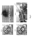
- Figure 2 presents pictures of an embodiment of a distributed spark obtainable with the method of the invention in a combustion chamber end view for a spark plug depicted in view AP in Figure 1 .
- view "a" item 1 denotes the electrode tip (item 9 in Figure 1 )
- item 2 denotes the insulator 2 (item 2 in Figure 1 )
- item 3 denotes the shell (item 4 in Figure 1 ).
- the sparks corresponding to the consecutive time moments i-3, i-2, i-1 and i start spatially next to each other and the direction of spark propagation tends to maintain. Accordingly, the hot spots produced by each spark at places where it contacts the electrodes are both spatially and temporally distributed.
- the corresponding discharge channels are distributed over the discharge gap.
- the discharge gap may have a variable thickness.
- the variable thickness is preferably 100% - 200% of the shortest distance between the electrodes forming the discharge gap.
- View “b” presents an image of plurality of the spatially distributed sparks; those skilled in the art will appreciate a uniform distribution of said sparks.
- View “c” presents a front view of a plug having a travelling spark. It will be appreciated that the view “c” is acquired with a camera adapted to register temporally consequent events, i.e. in the view “c” an imaginary X-axis represents time.
- View “d” presents a side view of plurality of distributed adjacent sparks. It is seen that a substantially volumetric travelling spark is produced in the region S. This has an advantage that substantially no degradation of the dielectric surface occurs, in contrast to the static non-travelling surface sparks known from the art. It is further found that such volumetric dynamic spark is more effective for igniting a suitable mixture than a static surface spark.
- Figure 3 presents in a schematic way an embodiment of a suitable voltage pulse shape when measured across the gap according to an aspect of the invention. It will be appreciated that for clarity reasons a single discharge voltage pulse U from a series of voltage pulses corresponding to an ignition burst is presented.
- the voltage pulse is characterized by a maximum amplitude Ubr, which is the discharge voltage, at least, equals to a breakdown voltage for a given plug. It will be appreciated that it is possible to apply voltages to the gap having the same or different polarities. Those skilled in the art will appreciate that in case of short duration voltage pulses fed to said spark plug through transmission line, preferably comprising coaxial cable, it is possible to use voltage pulses with an amplitude differs from the breakdown voltage of the gap. These pulses increase their amplitude when reflect from high-impedance load, limit peak discharge current, and favour distributed spark development.
- the conductivity current across the discharge gap should not exceed of about 10 mA for favouring development of the distributed sparks.
- conductivity current across the discharge gap should be substantially zero during an interval of at least 5% of a period between the consecutive breakdown voltage pulses of the ignition burst.
- Figure 4 presents oscillograms of voltage and current that correspond to a single spark from a plurality of distributed sparks over a spark plug depicted in Figure 2 .
- the plug is powered with a generator of nanosecond voltage pulses through a coaxial cable.
- Top curve depicts current through the plug.
- the scope of current oscillations is about 100 A, base level is 0 A.
- First peak corresponds to the breakdown and subsequent current oscillations are due to short-circuiting of the gap.
- Bottom curve corresponds to the voltage over the gap of said plug.
- First high amplitude peak corresponds to a pulse formed by generator until breakdown threshold is reached. Shortly after a spark channel is formed in the discharge gap, the voltage over the gap drops because a high conductivity channel is formed.
- FIG. 5 presents in a schematic way an embodiment of an ignition system according to an aspect of the invention.
- the voltage pulse generator 20, such as a suitable solid-state switch device is connected to the spark plug 22 using a transmission line L, preferably a coaxial cable.
- L preferably a coaxial cable.
- the duration of the leading edge of the voltage across the gap is smaller than the time of the voltage pulse propagation along said transmission line.
- a shunt capacitance C may be provided.
- said capacitance has a value of less than 3 nF.
- the coaxial cable L has impedance in the range of 10 - 300 Ohm.
- the power source 20 is directly connected to the plug 22.
- Figure 6 presents in a schematic way an embodiment of voltage bursts A, B, C according to a further aspect of the invention. Shown pulses amplitude and period relations and burst durations are indicative and do not limit present application, pulses amplitude within burst may change as long as considerable part of pulses provide distributed sparks.
- the bursts A, B and C are presented as a function of the crank angle (X-axis).
- the burst B corresponds to the ignition, the burst causes a plurality of distributed sparks to develop over the discharge gap of a spark plug which is installed inside combustion chamber of a spark ignition engine.
- the curve P represents the pressure development over the discharge gap while the curve T represents the temperature in the combustion chamber.
- the beginning of the ignition burst B is synchronized with a particular and regulatable crank angle, which is typically between -30 and -20 degrees of the crank. It will be appreciated that other synchronizations are possible depending on the type, geometry of the combustion chamber as well as the engine current load and revolution rate.
- the ignition burst of pulses B may be preceded by a burst of voltage pulses A, having an amplitude that may differ from that for burst B.
- Said burst A provides pre-treatment that is useful for tuning ignition properties of the mixture and can eliminate fouling film if occurred.
- Pulses A are preferably applied during compression.
- Said burst A application strategy may also be advantageous for engines running in HCCI mode when fine tuning of temperature and composition of mixture prior to main ignition is needed. It is possible to provide additional heating with combustion of very lean mixture provided by direct injection of small amount of fuel at early stage of compression cycle.
- Figure 7 presents two pressure profiles (Y-axis) obtained with a conventional ignition system 17a and with an ignition system based on the invention 19a in a cylinder of an engine operating with a fixed load and revolution rate. Standard deviation of cycle-to-cycle pressure profiles is also presented in the Figure for both systems, 17b for the conventional system and 19b for the system operating according to the method of the invention.
- use of ignition system based upon invention leads to remarkably lower cyclic variations and eliminates misfiring. Under the conditions of presented test, misfiring regularly happens with an ordinary system between +80 and +190 degrees of the crank (X-axis). For this particular case, about of 30% lower fuel consumption is obtained when practicing the invention due to a higher overall efficiency.
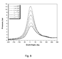
- Figure 8 presents pressure development in a cylinder (Y-axis) of an engine on the crank angle (X-axis) for the uniform lean-burn combustion for a fixed load and revolution rate with different levels of excess air ratio ⁇ .
- the engines designed for lean burning provide better performance, more efficient fuel use and lower exhaust emissions than those found in conventional engines.
- Figure 9 presents nitric oxide concentration in exhaust reduction (Y-axis, left) and exhaust temperature decrease (Y-axis, right) as a function of the crank angle (X-axis) for an engine operating in a uniform lean-burn regime using ignition system based on the invention for air excess factor ⁇ in the range 1.0 - 6.0. According to the results presented in Figure 9 an ignition system based upon the invention provides reliable ignition for such conditions as well as significant exhaust emission reduction and gas temperature decrease. These results are intended to be illustrative, not limiting.
Landscapes
- Engineering & Computer Science (AREA)
- Chemical & Material Sciences (AREA)
- Combustion & Propulsion (AREA)
- Mechanical Engineering (AREA)
- General Engineering & Computer Science (AREA)
- Spark Plugs (AREA)
Priority Applications (1)
| Application Number | Priority Date | Filing Date | Title |
|---|---|---|---|
| EP11176514A EP2554832A1 (fr) | 2011-08-04 | 2011-08-04 | Procédé d'allumage, bougie d'allumage et moteur utilisant la bougie d'allumage |
Applications Claiming Priority (1)
| Application Number | Priority Date | Filing Date | Title |
|---|---|---|---|
| EP11176514A EP2554832A1 (fr) | 2011-08-04 | 2011-08-04 | Procédé d'allumage, bougie d'allumage et moteur utilisant la bougie d'allumage |
Publications (1)
| Publication Number | Publication Date |
|---|---|
| EP2554832A1 true EP2554832A1 (fr) | 2013-02-06 |
Family
ID=44735815
Family Applications (1)
| Application Number | Title | Priority Date | Filing Date |
|---|---|---|---|
| EP11176514A Withdrawn EP2554832A1 (fr) | 2011-08-04 | 2011-08-04 | Procédé d'allumage, bougie d'allumage et moteur utilisant la bougie d'allumage |
Country Status (1)
| Country | Link |
|---|---|
| EP (1) | EP2554832A1 (fr) |
Cited By (2)
| Publication number | Priority date | Publication date | Assignee | Title |
|---|---|---|---|---|
| DE102013015063B3 (de) * | 2013-09-09 | 2015-03-05 | Michael Reimann | Verfahren und Vorrichtung zum Zünden eines Gas-Kraftstoff-Gemischs |
| WO2016191047A1 (fr) * | 2015-05-28 | 2016-12-01 | Caterpillar Inc. | Chambre de précombustion et son procédé de fonctionnement |
Citations (8)
| Publication number | Priority date | Publication date | Assignee | Title |
|---|---|---|---|---|
| FR1327226A (fr) * | 1962-04-05 | 1963-05-17 | Renault | Allumage à étincelles multiples pour moteurs à combustion interne |
| US4774914A (en) * | 1985-09-24 | 1988-10-04 | Combustion Electromagnetics, Inc. | Electromagnetic ignition--an ignition system producing a large size and intense capacitive and inductive spark with an intense electromagnetic field feeding the spark |
| EP0763759A2 (fr) * | 1995-09-14 | 1997-03-19 | Sumitomo Electric Industries, Inc. | Méthode et appareil de décharge électrique |
| US5947093A (en) * | 1994-11-08 | 1999-09-07 | Ignition Systems International, Llc. | Hybrid ignition with stress-balanced coils |
| US6131555A (en) * | 1998-04-20 | 2000-10-17 | Cummins Engine Company, Inc. | System for controlling ignition energy of an internal combustion engine |
| FR2904155A1 (fr) * | 2006-07-21 | 2008-01-25 | Peugeot Citroen Automobiles Sa | Systeme d'allumage et moteur a combustion interne comportant un tel systeme d'allumage |
| EP2020503A2 (fr) * | 2007-08-02 | 2009-02-04 | Nissan Motor Co., Ltd. | Dispositif d'allumage à décharge de plasma sans équilibre |
| WO2010090545A1 (fr) * | 2009-02-05 | 2010-08-12 | Neq Lab Holding Inc. | Procédé de formation d'un jet gazeux à enthalpie élevée basé sur une décharge gazeuse à impulsions |
-
2011
- 2011-08-04 EP EP11176514A patent/EP2554832A1/fr not_active Withdrawn
Patent Citations (8)
| Publication number | Priority date | Publication date | Assignee | Title |
|---|---|---|---|---|
| FR1327226A (fr) * | 1962-04-05 | 1963-05-17 | Renault | Allumage à étincelles multiples pour moteurs à combustion interne |
| US4774914A (en) * | 1985-09-24 | 1988-10-04 | Combustion Electromagnetics, Inc. | Electromagnetic ignition--an ignition system producing a large size and intense capacitive and inductive spark with an intense electromagnetic field feeding the spark |
| US5947093A (en) * | 1994-11-08 | 1999-09-07 | Ignition Systems International, Llc. | Hybrid ignition with stress-balanced coils |
| EP0763759A2 (fr) * | 1995-09-14 | 1997-03-19 | Sumitomo Electric Industries, Inc. | Méthode et appareil de décharge électrique |
| US6131555A (en) * | 1998-04-20 | 2000-10-17 | Cummins Engine Company, Inc. | System for controlling ignition energy of an internal combustion engine |
| FR2904155A1 (fr) * | 2006-07-21 | 2008-01-25 | Peugeot Citroen Automobiles Sa | Systeme d'allumage et moteur a combustion interne comportant un tel systeme d'allumage |
| EP2020503A2 (fr) * | 2007-08-02 | 2009-02-04 | Nissan Motor Co., Ltd. | Dispositif d'allumage à décharge de plasma sans équilibre |
| WO2010090545A1 (fr) * | 2009-02-05 | 2010-08-12 | Neq Lab Holding Inc. | Procédé de formation d'un jet gazeux à enthalpie élevée basé sur une décharge gazeuse à impulsions |
Non-Patent Citations (2)
| Title |
|---|
| J. WARNATZ, U. MAAS, R. W. DIBBLE: "Combustion", 2006, SPRINGER |
| RICHARD VAN BASSHUYSEN, FRED SHAFER: "Internal Combustion Engine Handbook", 2004, SAE INTERNATIONAL, pages: 417 - 421 |
Cited By (6)
| Publication number | Priority date | Publication date | Assignee | Title |
|---|---|---|---|---|
| DE102013015063B3 (de) * | 2013-09-09 | 2015-03-05 | Michael Reimann | Verfahren und Vorrichtung zum Zünden eines Gas-Kraftstoff-Gemischs |
| CN105579701A (zh) * | 2013-09-09 | 2016-05-11 | 迈克尔·莱曼 | 用于点火气体燃料混合物的方法和装置 |
| US9903336B2 (en) | 2013-09-09 | 2018-02-27 | Michael Reimann | Method and device for igniting a gas-fuel mixture |
| CN105579701B (zh) * | 2013-09-09 | 2018-08-17 | 迈克尔·莱曼 | 用于点火气体燃料混合物的方法和装置 |
| WO2016191047A1 (fr) * | 2015-05-28 | 2016-12-01 | Caterpillar Inc. | Chambre de précombustion et son procédé de fonctionnement |
| US20160348569A1 (en) * | 2015-05-28 | 2016-12-01 | Caterpillar Inc. | Combustion Pre-Chamber and Method for Operating Same |
Similar Documents
| Publication | Publication Date | Title |
|---|---|---|
| EP1801413B1 (fr) | Méthode et dispositif de commande d'une bougie à jet de plasma | |
| KR100317762B1 (ko) | 이동스파크점화시스템및이를위한점화장치 | |
| US4029072A (en) | Igniting apparatus for internal combustion engines | |
| US9951743B2 (en) | Plasma ignition device | |
| Yu et al. | Discharge characteristics of current boosted spark events under flow conditions | |
| CN1556564A (zh) | 超高能火花塞 | |
| KR20140045340A (ko) | 연소 제어 시스템, 회로, 및 방법 | |
| US9903336B2 (en) | Method and device for igniting a gas-fuel mixture | |
| US9377002B2 (en) | Electrodes for multi-point ignition using single or multiple transient plasma discharges | |
| US10830201B2 (en) | Ignition system having a high-frequency plasma-enhanced ignition spark of a spark plug, including an antechamber, and a method associated therewith | |
| Shiraishi et al. | A study of volumetric ignition using high-speed plasma for improving lean combustion performance in internal combustion engines | |
| Yang et al. | Effects of spark discharge energy Scheduling on flame kernel formation under quiescent and flow conditions | |
| EP2554832A1 (fr) | Procédé d'allumage, bougie d'allumage et moteur utilisant la bougie d'allumage | |
| US20130181629A1 (en) | Discharge device | |
| Yang et al. | A study of energy enhanced multi-spark discharge ignition in a constant-volume combustion chamber | |
| US20100212631A1 (en) | Combustion engine and method of controlling a combustion engine | |
| Yu et al. | Electrical waveform measurement of spark energy and its effect on lean burn SI engine combustion | |
| JP2002324649A (ja) | 内燃機関用点火装置および燃料室内に充填された燃料への点火方法 | |
| US11846262B2 (en) | Ignition coil control system and method | |
| KR20230037235A (ko) | 멀티 점화 코일 제어 시스템 | |
| Yu et al. | The effect of high-power capacitive spark discharge on the ignition and flame propagation in a lean and diluted cylinder charge | |
| Moriyoshi et al. | Combustion Enhancement in a Gas Engine Using Low Temperature Plasma | |
| US9133812B2 (en) | Ignition apparatus and ignition system | |
| JP6445322B2 (ja) | 内燃機関及びその制御方法 | |
| JP2010019203A (ja) | プラズマ式点火装置 |
Legal Events
| Date | Code | Title | Description |
|---|---|---|---|
| PUAI | Public reference made under article 153(3) epc to a published international application that has entered the european phase |
Free format text: ORIGINAL CODE: 0009012 |
|
| AK | Designated contracting states |
Kind code of ref document: A1 Designated state(s): AL AT BE BG CH CY CZ DE DK EE ES FI FR GB GR HR HU IE IS IT LI LT LU LV MC MK MT NL NO PL PT RO RS SE SI SK SM TR |
|
| AX | Request for extension of the european patent |
Extension state: BA ME |
|
| STAA | Information on the status of an ep patent application or granted ep patent |
Free format text: STATUS: THE APPLICATION IS DEEMED TO BE WITHDRAWN |
|
| 18D | Application deemed to be withdrawn |
Effective date: 20130807 |