EP0761390B1 - Spannelement - Google Patents
Spannelement Download PDFInfo
- Publication number
- EP0761390B1 EP0761390B1 EP96113296A EP96113296A EP0761390B1 EP 0761390 B1 EP0761390 B1 EP 0761390B1 EP 96113296 A EP96113296 A EP 96113296A EP 96113296 A EP96113296 A EP 96113296A EP 0761390 B1 EP0761390 B1 EP 0761390B1
- Authority
- EP
- European Patent Office
- Prior art keywords
- clamping
- clamping lever
- lever
- element according
- connecting rod
- Prior art date
- Legal status (The legal status is an assumption and is not a legal conclusion. Google has not performed a legal analysis and makes no representation as to the accuracy of the status listed.)
- Expired - Lifetime
Links
- 102000004315 Forkhead Transcription Factors Human genes 0.000 claims abstract description 5
- 108090000852 Forkhead Transcription Factors Proteins 0.000 claims abstract description 5
- 229910000639 Spring steel Inorganic materials 0.000 claims 3
- 239000011324 bead Substances 0.000 claims 1
- 238000000034 method Methods 0.000 description 6
- 238000013461 design Methods 0.000 description 5
- XEEYBQQBJWHFJM-UHFFFAOYSA-N Iron Chemical compound [Fe] XEEYBQQBJWHFJM-UHFFFAOYSA-N 0.000 description 4
- 238000010276 construction Methods 0.000 description 4
- 238000007789 sealing Methods 0.000 description 3
- 230000005540 biological transmission Effects 0.000 description 2
- 229910052742 iron Inorganic materials 0.000 description 2
- 239000007788 liquid Substances 0.000 description 2
- 238000003754 machining Methods 0.000 description 2
- 238000012546 transfer Methods 0.000 description 2
- 238000005452 bending Methods 0.000 description 1
- 210000000078 claw Anatomy 0.000 description 1
- 239000000428 dust Substances 0.000 description 1
- 238000003780 insertion Methods 0.000 description 1
- 230000037431 insertion Effects 0.000 description 1
- 230000002452 interceptive effect Effects 0.000 description 1
- 235000000396 iron Nutrition 0.000 description 1
- 230000002040 relaxant effect Effects 0.000 description 1
- 238000011160 research Methods 0.000 description 1
- 230000000284 resting effect Effects 0.000 description 1
Images

Classifications
-
- B—PERFORMING OPERATIONS; TRANSPORTING
- B25—HAND TOOLS; PORTABLE POWER-DRIVEN TOOLS; MANIPULATORS
- B25B—TOOLS OR BENCH DEVICES NOT OTHERWISE PROVIDED FOR, FOR FASTENING, CONNECTING, DISENGAGING OR HOLDING
- B25B5/00—Clamps
- B25B5/06—Arrangements for positively actuating jaws
- B25B5/061—Arrangements for positively actuating jaws with fluid drive
- B25B5/064—Arrangements for positively actuating jaws with fluid drive with clamping means pivoting around an axis perpendicular to the pressing direction
-
- B—PERFORMING OPERATIONS; TRANSPORTING
- B25—HAND TOOLS; PORTABLE POWER-DRIVEN TOOLS; MANIPULATORS
- B25B—TOOLS OR BENCH DEVICES NOT OTHERWISE PROVIDED FOR, FOR FASTENING, CONNECTING, DISENGAGING OR HOLDING
- B25B5/00—Clamps
- B25B5/06—Arrangements for positively actuating jaws
- B25B5/061—Arrangements for positively actuating jaws with fluid drive
-
- B—PERFORMING OPERATIONS; TRANSPORTING
- B25—HAND TOOLS; PORTABLE POWER-DRIVEN TOOLS; MANIPULATORS
- B25B—TOOLS OR BENCH DEVICES NOT OTHERWISE PROVIDED FOR, FOR FASTENING, CONNECTING, DISENGAGING OR HOLDING
- B25B5/00—Clamps
- B25B5/06—Arrangements for positively actuating jaws
- B25B5/12—Arrangements for positively actuating jaws using toggle links
- B25B5/122—Arrangements for positively actuating jaws using toggle links with fluid drive
Definitions
- the invention relates to a tensioning element for tensioning Workpieces on devices, machine tables and pallets by means of a piston in a housing that moves a connecting rod, which is connected to a rotatably mounted tensioning lever (see FR-A-2 157 696).
- Clamping elements are used to fix workpieces on tables and the like.
- the workpiece to be clamped is for the respective work step aligned accordingly on these tables and may then in his Location can no longer be changed.
- the clamping claws or clamping levers must therefore grip the workpiece so that it is in this position remains.
- Clamping elements, the clamping lever of which is first a sliding movement run over the part to be clamped, which then turns into a circular Clamping movement passes have the disadvantage that the on the workpiece applied forces do not strike vertically, but at angles and act because the pivot and support point are not at the same height Tension point is located. With this, the workpieces are often positioned out of theirs Location crazy.
- a clamping element is known (FR-A-2 157 696) in which a vertical guided differential piston by pressurizing one up and downward movement. There is a connecting rod on the piston head introduced in a ball guide.
- This connecting rod acts on a crank rod with which it is connected by means of a Joint eye is connected.
- the crank rod in turn, is fixed to the actual clamping lever connected via a common shaft.
- the connecting rod transfers the forces to a shaft transmits, at the end of which the clamping lever sits. So that will be in the wave Torrision forces and bending forces generated.
- stretching and relaxing the clamping lever describes approximately the same length at its clamping point Way like the end of the crank rod with the hinge eye of the connecting rod.
- the invention has for its object a smallest flat clamping element To create dimensions, the application of force approximately horizontal to workpiece to be clamped, and its clamping forces perpendicular to the work to be clamped, and which has a large clamping stroke and is also sealed against all types of pollution.
- the advantage of the invention lies in the small, flat design a large field of application allowed.
- the flat clamping element is now open Devices and pallets of all types can be used. Another advantage is given that the flat clamping element over a large clamping stroke and thus workpieces of different sizes can be assigned can. Further advantages lie in the sealing that the flat clamping element against external influences such as dust, machining chips and liquids, insensitive.
- the housing 1 is formed in the form of an open fork head 2.
- the Housing 1 has a piston bore 3 in which a piston 4 slides.
- the piston rod 5 is guided in a threaded bush 18, which at the same time as Sealing serves.
- a calotte 8 let in.
- a connecting rod 7 is guided to Forwarding the power transmission serves.
- the connecting rod 7 has on their both ends have an approximately equal spherical head 9a and 9b.
- the Ball head 9a is mounted in the calotte 8 and can thus be around move the specified degree of freedom.
- the ball head 9b is also stored in a calotte 10, in which it is with the predetermined degree of freedom can move.
- the cap 10 in turn is in the clamping lever 11 let in. This tensioning lever 11 forms a in the area of the calotte 10 Pocket 12.
- the connecting rod 7 becomes a free space in the movement procured.
- a small hole 14 is made, in which a Driving pin 15 is guided.
- This driving pin 15 supports the Return process of the clamping lever 11 by a guide within the Pocket 12 and thus keeps the ball head 9b in contact with the calotte 10.
- Pressure chambers 16 and 17 formed, of which pressure chamber 16 for the Clamping process and pressure chamber 17 serve for the relaxation process.
- the inner spring plate 19 has a contour that corresponds to the outer contour of the stroke on the circumference of the Clamping lever 11 is adjusted with the entire length so that it slides is guided on the spring plate 19.
- the lower spring plate 20 is in his Contour adapted to the lower contours of the clamping lever 11, so that too here a tight seal with sliding movement of the clamping lever 11 is reached.
- Another spring plate 21 provides a connection between the Housing 1 and the spring plate 19 resting on the tensioning lever 11.
- the piston 4 is guided in a threaded bushing 18 with the corresponding Seals is fitted. This threaded bushing 18 is in the threaded bore 6 of the housing 1 screwed in and can thus if necessary can be easily replaced.
- the clamping lever 11 is formed on its clamping surface so that it is flat the workpiece 25 is seated.
- a dome 22 is in the clamping head introduced which receives a flattened ball 23.
- the Clamping lever 11 in the area of its clamping head with a constriction 24 and bevelled 29.
- This constriction 24 and also the Bevel 29 serve to improve the shape to ensure a safe
- This is of particular advantage when there are large height differences of workpieces to be clamped.
- Through the constriction 24 and the bevel 29 becomes the flattened spherical cap 23 22 weakened in their holding surface.
- lateral enclosures 27 are Clamping head provided, which expand the spherical guide without the clamping stroke hindered by interfering edges.
- the housing 1 is attached to the respective by means of fastening screws Machining plate fixed. If the pressure chamber 16 is applied, so the piston 4 slides with the piston rod guided in the threaded bushing 18 5 towards the workpiece. This will initiate the Transfer force to the connecting rod 7, which in turn is direct, i.e. without Crank rod, acts on the clamping lever 11.
- This tension lever 11 performs about its pivot point, the cylindrical pin 13, a rotational movement towards the exciting workpiece 25 too.
- the clamping lever 11 is always with the Hit the flattened side of the ball 23 on the workpiece 25.
- This bullet 23 thus largely resembles the clamping force running on a circular path and ensures even placement on the workpiece and for even force transmission into the workpiece.
- Through the Bevel 29 and the constriction 24 is during the tensioning process ensured that the clamping lever 11 only with the surface of the flattened ball 23 is seated, regardless of the heights of the exciting workpieces.
- the clamping lever 11 With its outer contour, the clamping lever 11 forms approximately a quarter circle. This allows the center of the ball head 9b, the cylinder pin center 13 and the surface of the clamping ball 23 approximately at an angle of 90 ° be positioned to each other. This has a horizontal arrangement of the Connecting rod 7, piston rod 5 with piston 4 result.
- the tension lever 11 is designed differently in its cross section. In the area of the forks is he trained the thickest while he was in the area of his operative intervention is only provided with such a cross section as it is for Insertion of the spherical cap and thus for receiving the flattened ball is required.
- pressure chamber 17 is pressurized, whereby the piston 4 in the piston bore 3 in the direction of the workpiece slides away and the hydraulic in the pressure chamber 16 Squeezes out liquid.
- the piston rod 5 pulls the connecting rod 7 back, which in turn retrieves the tensioning lever 11 via the driving pin 15.
- the point of engagement of the connecting rod 7 on the tensioning lever 11 is in the range above the pivot point of the clamping lever 11 in the cylinder pin 13. So these two points 13 and 14 can be brought close together, which contributes to a short design of the clamping element and thus the Piston stroke minimized.
- the particularly space-saving short and low Last but not least, the design of the clamping element comes from the minimal Piston stroke.
- the short piston stroke which has a large opening path of the clamping lever results because the pressure point of the small Connecting rod ball and the associated calotte of the tension lever are arranged extremely close to the clamping lever pivot point.
- the pocket in the clamping lever ensures an optimal arrangement of the center of the ball of the connecting rod, so that in the tensioned position the axis through the Connecting rod and straight through the piston rod.
- the distance between the center of the sphere 9b and the center of rotation in the cylinder 13 for the clamping lever 11 is approximately half the distance between the center point of the flattened ball 23 arranged in the clamping head and the center of the clamping lever in the cylinder 13. This is the Piston guide only due to the stroke of the clamping lever, which is the short construction supported.
- the fork head forms the two forks 2a and 2b.
- Bores 28 are introduced, in which the cylindrical pin or pins 13 are guided are.
- One or two cylindrical pins in the clamping element are useful arranged. These pins can be screwed into the forks from the outside or also be pressed. The clamping element can be rotated about this axis stored.
Landscapes
- Engineering & Computer Science (AREA)
- Mechanical Engineering (AREA)
- Jigs For Machine Tools (AREA)
- Bidet-Like Cleaning Device And Other Flush Toilet Accessories (AREA)
- Road Signs Or Road Markings (AREA)
Description
- Fig. 1
- zeigt den Querschnitt in einer Seitenansicht
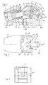
- Fig. 2
- zeigt eine Draufsicht
- Fig. 3
- zeigt die Lagerung des Spannkopfes
- Fig. 4
- zeigt den Spannhebel in Ruhestellung
- Fig. 5
- zeigt den Spannhebel während des Spannvorganges und
- Fig. 6
- zeigt den Spannhebel im Spannzustand.
Claims (12)
- Spannelement zum Spannen von Werkstücken auf Vorrichtungen , Tischen oder Paletten, bestehend aus einem Gehäuse (1), in dem ein Kolben (4) geführt ist, der über ein Kugelgelenk mit einer Pleuelstange verbunden ist, die auf einen Spannhebel wirkt, wobei der Spanehebel in einem im Gehäuse (1) gebildeten Gabelkopf drehbar gelagert ist, dadurch gekennzeichnet, daß die Pleuelstange (7) an ihren beiden Enden je einen annähernd gleich großen Kugelkopf (9a;9b) trägt und der eine Kugelkopf (9a) in einer Kalotte (8) am Ende einer als Teil des Kolbens (4) gebildeten Kolbenstange (5) umbördelt eingebracht ist und der andere Kugelkopf (9b) in einer dem Spannhebel (11) zugeordneten Kalotte (10) mittels eines Mitnahmestiftes (15) gehalten ist, so daß so daß die Achsen von der Kolbenstange (5) und der Pleuelstange (7) auf einer einziegen Achse zusammen fallen können und die auf die Pleuelstange (7) einwirkende Kraft direkt auf den Spannhebel (11) übertragbar ist und diesen um seine Drehachse, gebildet durch einen im Gabelkopf (2) geführten Zylinderstift (13), dreht und auf ein zugeordnetes Werkstück (25) mit einer im Spannhebelende drehbar gelagerten abgeflachten Kugel (23) aufsetzt und der Spannhebel (11) im entspannten Zustand in einen Raum des Gehäuses (1), der durch Federbleche (19;20) gegen äussere Einflüsse abgedichtet ist, zurückfährt und daß der Abstand zwischen der Kugelkopfmitte der anderen Pleuelstangenkugel (9b) im Spannhebel (11) zur Mitte des Zylinderstiftes (13) als Spannhebeldrehpunkt etwa die Hälfte des Abstandes zwischen Spannhebeldrehpunkt und mittleren Aufsetzpunkt auf das Werkstück (25), durch die dem Spannhebel zugeordneten abgeflachte Kugel (23), beträgt.
- Spannelement nach Anspruch 1, dadurch gekennzeichnet, daß der Krafteinleitungspunkt des Kolben (4) über Kolbenstange (5), Pleuel (7) und die Kugelköpfe (9a;9b) nahe und oberhalb des Drehpunktes des Spannhebels (11) liegt.
- Spannelement nach Anspruch 2, dadurch gekennzeichnet, daß in den Spannhebel (11) im Bereich des Kugelkopfeingriffes der Pleuelstange (7) eine Tasche (12) eingebracht ist.
- Spannelement nach Anspruch 1, dadurch gekennzeichnet, daß der Kugelkopf (9b) in der Kalotte (10) des Spannhebels (11) mittig mit einer Bohrung (14) versehen ist, in der der Mitnahmestift (15) eingebracht ist.
- Spannelement nach Anspruch 1, dadurch gekennzeichnet, daß das innere Federblech (19) und das untere Federblech (20) in ihren Konturen so ausgebildet sind, daß der Spannhebel (11) während semer Schwenkbewegung darin gleitend anliegt.
- Spannelement nach Anspruch 1, dadurch gekennzeichnet, daß die Kugel (23) in einer an zwei Seiten dachförmig abgeschrägten Spannkugelkalotte (22) im Spannhebel (11) seitenbeweglich geführt ist.
- Spannelement nach Anspruch 6, dadurch gekennzeichnet, daß der Spannhebel (11) im Bereich der Spannkugelkalotte (22) eine seitliche Umfassung (27) zur Halterung der abgeflachten Kugel (23) besitzt.
- Spannelement nach Anspruch 1 bis 6, dadurch gekennzeichnet, daß der Spannhebel (11) im Bereich der Spannebene eine nach innen gerichtete Einschnürung (24) aufweist.
- Spannelement nach Anspruch 1 bis 6, dadurch gekennzeichnet, daß die Kolbenstange (5) in einer Gewindebuchse (18) geführt ist, die die Kolbenstange abdichtet.
- Spannelemente nach Anspruch 9, dadurch gekennzeichnet, daß in dem Gehäuse (1) eine Gewindebohrung (6) eingebracht ist, in die die Gewindebuchse (18) einschraubbar ist.
- Spannelement nach Anspruch 1, dadurch gekennzeichnet, daß die Mittelpunkte der beiden Kugelköpfe (9a;9b) der Pleuelstange (7) annähernd die gleiche Entfernung voneinander haben, wie der Mittelpunkt, der im Spannhebel (11) wirksamen Kugel (9b) zu Drehpunkt des Spannhebels (11).
- Spannelement nach Anspruch 6-11, dadurch gekennzeichnet, daß im Spannhebel (11) der Mittelpunkt der Kalotte (10), die Drehachse des Zylinderstifts (13) und die Spannfläche der Kugel (23) einen Winkel von etwa 90° zueinander bilden, wobei der Spannhebel mit seiner Außenkontur etwa einen Viertelkreis beschreibt.
Applications Claiming Priority (2)
| Application Number | Priority Date | Filing Date | Title |
|---|---|---|---|
| DE19531890 | 1995-08-30 | ||
| DE19531890A DE19531890A1 (de) | 1995-08-30 | 1995-08-30 | Flachspannelement |
Publications (2)
| Publication Number | Publication Date |
|---|---|
| EP0761390A1 EP0761390A1 (de) | 1997-03-12 |
| EP0761390B1 true EP0761390B1 (de) | 2001-10-31 |
Family
ID=7770755
Family Applications (1)
| Application Number | Title | Priority Date | Filing Date |
|---|---|---|---|
| EP96113296A Expired - Lifetime EP0761390B1 (de) | 1995-08-30 | 1996-08-20 | Spannelement |
Country Status (4)
| Country | Link |
|---|---|
| EP (1) | EP0761390B1 (de) |
| AT (1) | ATE207788T1 (de) |
| DE (2) | DE19531890A1 (de) |
| ES (1) | ES2166420T3 (de) |
Cited By (3)
| Publication number | Priority date | Publication date | Assignee | Title |
|---|---|---|---|---|
| DE102007050946A1 (de) | 2007-10-23 | 2009-04-30 | Frank Entzmann | Spannvorrichtung |
| DE102016200149A1 (de) | 2016-01-08 | 2017-07-13 | Ladenburger Fertigungstechnik Gmbh | Vorrichtung zum Spannen von Werkstücken |
| EP4183519A1 (de) * | 2021-11-18 | 2023-05-24 | SMC Corporation | Luftspannfutter mit drehpunktöffnung/-schliessung |
Families Citing this family (4)
| Publication number | Priority date | Publication date | Assignee | Title |
|---|---|---|---|---|
| DE102004043303B4 (de) | 2004-09-08 | 2018-07-26 | Andreas Maier Gmbh & Co. Kg | Spannsystem für Bearbeitungszentren |
| DE102008004286A1 (de) * | 2008-01-04 | 2009-07-09 | Vel Vega-Design E Tecnologia Ind. Unip. Lda., Funchal | Spannelement |
| DE102017104868A1 (de) | 2017-03-08 | 2018-09-13 | Karin Schmid E. K. | Schwenkspanner für Automatisierungszwecke |
| IT202100017555A1 (it) * | 2021-07-02 | 2023-01-02 | Hydroblock S R L | Apparecchio per il bloccaggio di pezzi su macchine utensili |
Family Cites Families (8)
| Publication number | Priority date | Publication date | Assignee | Title |
|---|---|---|---|---|
| US3724837A (en) * | 1970-09-02 | 1973-04-03 | Dover Corp | Retracting clamp |
| FR2157696B3 (de) * | 1971-10-26 | 1974-06-07 | Maac Ets | |
| US4721293A (en) * | 1986-08-12 | 1988-01-26 | Jergens, Inc. | Self-locking clamping device |
| DE4111430A1 (de) * | 1990-04-12 | 1991-10-17 | Volker Schlueter | Druckmittelbetaetigte spannvorrichtung |
| DE4307058A1 (de) * | 1993-03-06 | 1994-09-08 | David Fischer | Spannvorrichtung zum Spannen von Werkstücken auf Maschinentischen oder Paletten |
| DE4311857A1 (de) * | 1993-04-10 | 1994-10-13 | David Fischer | Spannvorrichtung zum Spannen von Werkstücken |
| DE4337658C1 (de) * | 1993-11-04 | 1995-05-04 | Frey Rudolf | Spannpratze |
| DE29505573U1 (de) * | 1995-03-31 | 1995-05-24 | Maschinenfabrik Wagner GmbH & Co KG, 53804 Much | Druckbetriebener Kraftschrauber |
-
1995
- 1995-08-30 DE DE19531890A patent/DE19531890A1/de not_active Withdrawn
-
1996
- 1996-08-20 EP EP96113296A patent/EP0761390B1/de not_active Expired - Lifetime
- 1996-08-20 ES ES96113296T patent/ES2166420T3/es not_active Expired - Lifetime
- 1996-08-20 AT AT96113296T patent/ATE207788T1/de active
- 1996-08-20 DE DE59608048T patent/DE59608048D1/de not_active Expired - Lifetime
Cited By (5)
| Publication number | Priority date | Publication date | Assignee | Title |
|---|---|---|---|---|
| DE102007050946A1 (de) | 2007-10-23 | 2009-04-30 | Frank Entzmann | Spannvorrichtung |
| DE102007050946B4 (de) * | 2007-10-23 | 2009-08-13 | Frank Entzmann | Spannvorrichtung |
| DE102016200149A1 (de) | 2016-01-08 | 2017-07-13 | Ladenburger Fertigungstechnik Gmbh | Vorrichtung zum Spannen von Werkstücken |
| DE102016200149B4 (de) * | 2016-01-08 | 2020-09-03 | Ladenburger Fertigungstechnik Gmbh | Vorrichtung zum Spannen von Werkstücken |
| EP4183519A1 (de) * | 2021-11-18 | 2023-05-24 | SMC Corporation | Luftspannfutter mit drehpunktöffnung/-schliessung |
Also Published As
| Publication number | Publication date |
|---|---|
| DE59608048D1 (de) | 2001-12-06 |
| ES2166420T3 (es) | 2002-04-16 |
| DE19531890A1 (de) | 1997-03-06 |
| EP0761390A1 (de) | 1997-03-12 |
| ATE207788T1 (de) | 2001-11-15 |
Similar Documents
| Publication | Publication Date | Title |
|---|---|---|
| DE3031368A1 (de) | Schwenkspanner | |
| DE19732600C2 (de) | Bauteilspanner | |
| EP0761390B1 (de) | Spannelement | |
| EP0650832A1 (de) | Vorrichtung zum Aufspannen eines Gewebestückes | |
| DE19531889A1 (de) | Spannelement | |
| EP0572748B1 (de) | Ringventil für einen Kolbenkompressor | |
| DE3601225C1 (de) | Wechselkopf fuer eine Werkzeugwechselvorrichtung | |
| DE10005321A1 (de) | Vorrichtung zur schwimmenden Spannung eines zu bearbeitenden Werkstückes | |
| DE4008088A1 (de) | Schweissvorrichtung mit x-foermiger schweisszangenanordnung | |
| DE3528443C2 (de) | ||
| DE2633653B2 (de) | Verschluß für kreisrunde Öffnungen mit großem Durchmesser | |
| DD202274A5 (de) | Schienenzange | |
| DE3314646C2 (de) | Vorrichtung zum Widerstandsschweißen | |
| CH657802A5 (de) | Vorrichtung zur lagefixierung von werkstuecktraegern auf werkzeugmaschinen. | |
| EP0980818A2 (de) | Spannvorrichtung | |
| DE3726078C1 (en) | Catch device for a drill string of a rock-drilling machine | |
| DE1552608C3 (de) | Spannvorrichtung mit einer feststehenden und einer beweglichen Spannbacke | |
| DE19955289A1 (de) | Buchsenziehvorrichtung | |
| DE10053230A1 (de) | Spannfutter für eine Vorrichtung zum Polieren von Linsen und Vorrichtung mit einem solchen Spannfutter | |
| DE10003449C2 (de) | Hydraulischer Universal-Spannturm in Modulbauweise | |
| DE102004060643B4 (de) | Vorrichtung zum Verschweißen der Halbschalen eines Behälters | |
| DE2945782C2 (de) | Spannvorrichtung bei einer Anordnung für die Verstellung der Hublänge eines Hubmotors | |
| DE1157438B (de) | Stoesselfuehrung mit Stoessel und Einstellelement | |
| DE2618932A1 (de) | Hydraulisch betaetigbarer spannzylinder | |
| DE3101523C2 (de) | Sicherheitsventil |
Legal Events
| Date | Code | Title | Description |
|---|---|---|---|
| PUAI | Public reference made under article 153(3) epc to a published international application that has entered the european phase |
Free format text: ORIGINAL CODE: 0009012 |
|
| AK | Designated contracting states |
Kind code of ref document: A1 Designated state(s): AT CH DE ES FR GB IT LI |
|
| 17P | Request for examination filed |
Effective date: 19970509 |
|
| 17Q | First examination report despatched |
Effective date: 19980210 |
|
| GRAG | Despatch of communication of intention to grant |
Free format text: ORIGINAL CODE: EPIDOS AGRA |
|
| GRAG | Despatch of communication of intention to grant |
Free format text: ORIGINAL CODE: EPIDOS AGRA |
|
| GRAH | Despatch of communication of intention to grant a patent |
Free format text: ORIGINAL CODE: EPIDOS IGRA |
|
| GRAH | Despatch of communication of intention to grant a patent |
Free format text: ORIGINAL CODE: EPIDOS IGRA |
|
| GRAA | (expected) grant |
Free format text: ORIGINAL CODE: 0009210 |
|
| AK | Designated contracting states |
Kind code of ref document: B1 Designated state(s): AT CH DE ES FR GB IT LI |
|
| PG25 | Lapsed in a contracting state [announced via postgrant information from national office to epo] |
Ref country code: FR Free format text: LAPSE BECAUSE OF FAILURE TO SUBMIT A TRANSLATION OF THE DESCRIPTION OR TO PAY THE FEE WITHIN THE PRESCRIBED TIME-LIMIT Effective date: 20011031 |
|
| REF | Corresponds to: |
Ref document number: 207788 Country of ref document: AT Date of ref document: 20011115 Kind code of ref document: T |
|
| REG | Reference to a national code |
Ref country code: CH Ref legal event code: EP |
|
| REF | Corresponds to: |
Ref document number: 59608048 Country of ref document: DE Date of ref document: 20011206 |
|
| REG | Reference to a national code |
Ref country code: GB Ref legal event code: IF02 |
|
| GBT | Gb: translation of ep patent filed (gb section 77(6)(a)/1977) |
Effective date: 20020106 |
|
| REG | Reference to a national code |
Ref country code: CH Ref legal event code: NV Representative=s name: BOVARD AG PATENTANWAELTE |
|
| REG | Reference to a national code |
Ref country code: ES Ref legal event code: FG2A Ref document number: 2166420 Country of ref document: ES Kind code of ref document: T3 |
|
| PLBE | No opposition filed within time limit |
Free format text: ORIGINAL CODE: 0009261 |
|
| STAA | Information on the status of an ep patent application or granted ep patent |
Free format text: STATUS: NO OPPOSITION FILED WITHIN TIME LIMIT |
|
| 26N | No opposition filed | ||
| REG | Reference to a national code |
Ref country code: CH Ref legal event code: PFA Owner name: FISCHER, DAVID Free format text: FISCHER, DAVID#HAYDNSTRASSE 4#D-63743 ASCHAFFENBURG (DE) -TRANSFER TO- FISCHER, DAVID#HAYDNSTRASSE 4#D-63743 ASCHAFFENBURG (DE) |
|
| REG | Reference to a national code |
Ref country code: DE Ref legal event code: R082 Ref document number: 59608048 Country of ref document: DE Representative=s name: ZACCO DR. PETERS UND PARTNER, DE |
|
| REG | Reference to a national code |
Ref country code: DE Ref legal event code: R082 Ref document number: 59608048 Country of ref document: DE Representative=s name: ZACCO DR. PETERS UND PARTNER, DE |
|
| PGFP | Annual fee paid to national office [announced via postgrant information from national office to epo] |
Ref country code: CH Payment date: 20150824 Year of fee payment: 20 Ref country code: ES Payment date: 20150825 Year of fee payment: 20 Ref country code: GB Payment date: 20150824 Year of fee payment: 20 Ref country code: DE Payment date: 20150831 Year of fee payment: 20 |
|
| PGFP | Annual fee paid to national office [announced via postgrant information from national office to epo] |
Ref country code: AT Payment date: 20150820 Year of fee payment: 20 |
|
| PGFP | Annual fee paid to national office [announced via postgrant information from national office to epo] |
Ref country code: IT Payment date: 20150827 Year of fee payment: 20 |
|
| REG | Reference to a national code |
Ref country code: DE Ref legal event code: R071 Ref document number: 59608048 Country of ref document: DE |
|
| REG | Reference to a national code |
Ref country code: CH Ref legal event code: PL |
|
| REG | Reference to a national code |
Ref country code: GB Ref legal event code: PE20 Expiry date: 20160819 |
|
| REG | Reference to a national code |
Ref country code: AT Ref legal event code: MK07 Ref document number: 207788 Country of ref document: AT Kind code of ref document: T Effective date: 20160820 |
|
| PG25 | Lapsed in a contracting state [announced via postgrant information from national office to epo] |
Ref country code: GB Free format text: LAPSE BECAUSE OF EXPIRATION OF PROTECTION Effective date: 20160819 |
|
| REG | Reference to a national code |
Ref country code: ES Ref legal event code: FD2A Effective date: 20161125 |
|
| PG25 | Lapsed in a contracting state [announced via postgrant information from national office to epo] |
Ref country code: ES Free format text: LAPSE BECAUSE OF EXPIRATION OF PROTECTION Effective date: 20160821 |