EP0761331B1 - Verfahren zur Beseitigung der Grate in einem kontinuierlichen Walzverfahren und Gerät dafür - Google Patents
Verfahren zur Beseitigung der Grate in einem kontinuierlichen Walzverfahren und Gerät dafür Download PDFInfo
- Publication number
- EP0761331B1 EP0761331B1 EP96113917A EP96113917A EP0761331B1 EP 0761331 B1 EP0761331 B1 EP 0761331B1 EP 96113917 A EP96113917 A EP 96113917A EP 96113917 A EP96113917 A EP 96113917A EP 0761331 B1 EP0761331 B1 EP 0761331B1
- Authority
- EP
- European Patent Office
- Prior art keywords
- travelling
- billet
- billets
- grinding
- grinders
- Prior art date
- Legal status (The legal status is an assumption and is not a legal conclusion. Google has not performed a legal analysis and makes no representation as to the accuracy of the status listed.)
- Expired - Lifetime
Links
- 238000005096 rolling process Methods 0.000 title claims abstract description 65
- 238000000034 method Methods 0.000 title claims abstract description 58
- 238000003466 welding Methods 0.000 claims abstract description 46
- 238000005304 joining Methods 0.000 claims abstract description 11
- XLYOFNOQVPJJNP-UHFFFAOYSA-N water Substances O XLYOFNOQVPJJNP-UHFFFAOYSA-N 0.000 claims description 27
- 238000011144 upstream manufacturing Methods 0.000 claims description 19
- 239000007921 spray Substances 0.000 claims description 11
- 238000001514 detection method Methods 0.000 claims description 8
- 230000001174 ascending effect Effects 0.000 claims description 4
- 230000033001 locomotion Effects 0.000 abstract description 7
- 239000002893 slag Substances 0.000 description 70
- 230000009471 action Effects 0.000 description 14
- 239000000428 dust Substances 0.000 description 8
- 229910000831 Steel Inorganic materials 0.000 description 7
- 238000009749 continuous casting Methods 0.000 description 7
- 239000010959 steel Substances 0.000 description 7
- 230000007246 mechanism Effects 0.000 description 6
- 230000008859 change Effects 0.000 description 4
- 238000005299 abrasion Methods 0.000 description 3
- 230000007547 defect Effects 0.000 description 3
- 238000010438 heat treatment Methods 0.000 description 3
- 230000008569 process Effects 0.000 description 3
- 230000001105 regulatory effect Effects 0.000 description 3
- 230000001360 synchronised effect Effects 0.000 description 3
- 206010039509 Scab Diseases 0.000 description 2
- 230000005540 biological transmission Effects 0.000 description 2
- 238000005266 casting Methods 0.000 description 2
- 230000006698 induction Effects 0.000 description 2
- 230000013011 mating Effects 0.000 description 2
- 230000004044 response Effects 0.000 description 2
- 238000000926 separation method Methods 0.000 description 2
- 238000009825 accumulation Methods 0.000 description 1
- 239000011324 bead Substances 0.000 description 1
- 238000001816 cooling Methods 0.000 description 1
- 230000002950 deficient Effects 0.000 description 1
- 230000001419 dependent effect Effects 0.000 description 1
- 238000010586 diagram Methods 0.000 description 1
- 238000002347 injection Methods 0.000 description 1
- 239000007924 injection Substances 0.000 description 1
- 230000002452 interceptive effect Effects 0.000 description 1
- 238000002955 isolation Methods 0.000 description 1
- 230000002093 peripheral effect Effects 0.000 description 1
- 230000002459 sustained effect Effects 0.000 description 1
Images


Classifications
-
- B—PERFORMING OPERATIONS; TRANSPORTING
- B21—MECHANICAL METAL-WORKING WITHOUT ESSENTIALLY REMOVING MATERIAL; PUNCHING METAL
- B21B—ROLLING OF METAL
- B21B15/00—Arrangements for performing additional metal-working operations specially combined with or arranged in, or specially adapted for use in connection with, metal-rolling mills
- B21B15/0085—Joining ends of material to continuous strip, bar or sheet
-
- B—PERFORMING OPERATIONS; TRANSPORTING
- B24—GRINDING; POLISHING
- B24B—MACHINES, DEVICES, OR PROCESSES FOR GRINDING OR POLISHING; DRESSING OR CONDITIONING OF ABRADING SURFACES; FEEDING OF GRINDING, POLISHING, OR LAPPING AGENTS
- B24B5/00—Machines or devices designed for grinding surfaces of revolution on work, including those which also grind adjacent plane surfaces; Accessories therefor
- B24B5/36—Single-purpose machines or devices
- B24B5/38—Single-purpose machines or devices for externally grinding travelling elongated stock, e.g. wire
-
- B—PERFORMING OPERATIONS; TRANSPORTING
- B21—MECHANICAL METAL-WORKING WITHOUT ESSENTIALLY REMOVING MATERIAL; PUNCHING METAL
- B21B—ROLLING OF METAL
- B21B1/00—Metal-rolling methods or mills for making semi-finished products of solid or profiled cross-section; Sequence of operations in milling trains; Layout of rolling-mill plant, e.g. grouping of stands; Succession of passes or of sectional pass alternations
- B21B1/02—Metal-rolling methods or mills for making semi-finished products of solid or profiled cross-section; Sequence of operations in milling trains; Layout of rolling-mill plant, e.g. grouping of stands; Succession of passes or of sectional pass alternations for rolling heavy work, e.g. ingots, slabs, blooms, or billets, in which the cross-sectional form is unimportant ; Rolling combined with forging or pressing
- B21B1/04—Metal-rolling methods or mills for making semi-finished products of solid or profiled cross-section; Sequence of operations in milling trains; Layout of rolling-mill plant, e.g. grouping of stands; Succession of passes or of sectional pass alternations for rolling heavy work, e.g. ingots, slabs, blooms, or billets, in which the cross-sectional form is unimportant ; Rolling combined with forging or pressing in a continuous process
-
- B—PERFORMING OPERATIONS; TRANSPORTING
- B21—MECHANICAL METAL-WORKING WITHOUT ESSENTIALLY REMOVING MATERIAL; PUNCHING METAL
- B21B—ROLLING OF METAL
- B21B1/00—Metal-rolling methods or mills for making semi-finished products of solid or profiled cross-section; Sequence of operations in milling trains; Layout of rolling-mill plant, e.g. grouping of stands; Succession of passes or of sectional pass alternations
- B21B1/46—Metal-rolling methods or mills for making semi-finished products of solid or profiled cross-section; Sequence of operations in milling trains; Layout of rolling-mill plant, e.g. grouping of stands; Succession of passes or of sectional pass alternations for rolling metal immediately subsequent to continuous casting
- B21B1/466—Metal-rolling methods or mills for making semi-finished products of solid or profiled cross-section; Sequence of operations in milling trains; Layout of rolling-mill plant, e.g. grouping of stands; Succession of passes or of sectional pass alternations for rolling metal immediately subsequent to continuous casting in a non-continuous process, i.e. the cast being cut before rolling
-
- B—PERFORMING OPERATIONS; TRANSPORTING
- B21—MECHANICAL METAL-WORKING WITHOUT ESSENTIALLY REMOVING MATERIAL; PUNCHING METAL
- B21B—ROLLING OF METAL
- B21B1/00—Metal-rolling methods or mills for making semi-finished products of solid or profiled cross-section; Sequence of operations in milling trains; Layout of rolling-mill plant, e.g. grouping of stands; Succession of passes or of sectional pass alternations
- B21B1/02—Metal-rolling methods or mills for making semi-finished products of solid or profiled cross-section; Sequence of operations in milling trains; Layout of rolling-mill plant, e.g. grouping of stands; Succession of passes or of sectional pass alternations for rolling heavy work, e.g. ingots, slabs, blooms, or billets, in which the cross-sectional form is unimportant ; Rolling combined with forging or pressing
- B21B2001/022—Blooms or billets
Claims (14)
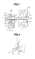
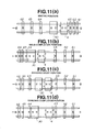
- Verfahren zum Entfernen von Graten in einem Bandwalzverfahren, umfassend folgende Schritte:Fügen eines hinteren Endes eines vorlaufenden Knüppels (10) mit einem vorderen Ende eines nachfolgenden Knüppels (11) durch Stumpfbrennschweissen und während sowohl der vorlaufende Knüppel als auch der nachfolgende Knüppel verfahren; undSchleifen eines Grats (13) auf dem Schweissteil (10a) der gefügten vorlaufenden und nachfolgenden Knüppel mit einer Vielzahl von Schleifern (31, 32, 33; 41, 42, 43, 44), während die gefügten Knüppel verfahren und die Schleifer sich drehen und sich synchron mit der Verfahrgeschwindigkeit der und in dieselbe Richtung wie die gefügten Knüppel bewegen.
- Verfahren nach Anspruch 1, weiterhin umfassend:Erfassen eines geschweissten Abschnitts (10a) auf Knüppeln durch Verwenden eines an einer verfahrenden Schleifmaschine (30) befestigten Sensors (90), wobei die verfahrende Schleifmaschine stromabwärts des Schweissschritts gelegen ist;Voreinstellen der sich kontinuierlich drehenden Vielzahl von Schleifern (31, 32, 33; 41, 42, 43, 44) auf den Knüppel unmittelbar nach dem Erfassen des geschweissten Abschnitts, wobei die Schleifer an der verfahrenden Schleifmaschine (30) befestigt sind, und der Schritt des Voreinstellens durchgeführt wird, während sich die verfahrende Schleifmaschine in eine stromabwärtige Richtung der gefügten Knüppel (10, 11) bewegt;Beschleunigen der verfahrenden Schleifmaschine (30) auf eine Verfahrgeschwindigkeit der gefügten Knüppel (10, 11);Erfassen, dass der geschweisste Abschnitt (10a) der gefügten Knüppel bei einer Position der Vielzahl von Schleifern ankommt; undDurchführen des Schritts des Schleifens eines Grats durch Festsetzen der Schleifer bei der voreingestellten Position, nachdem die Ankunft des geschweissten Abschnitts der gefügten Knüppel erfasst wurde.
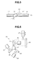
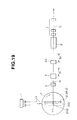
- Verfahren nach Anspruch 1 oder 2, weiterhin für einen Rundknüppel und bei dem Schritt des Schleifens eines Grats auf dem geschweissten Abschnitt das Umlaufenlassen der Vielzahl von Schleifern (31, 32, 33) umfassend, wobei die Schleifer in gleichmässigen Abständen auf einem Umfang des Rundknüppels um einen vorherbestimmten Winkel beabstandet angeordnet sind.
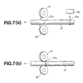
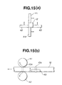
- Verfahren nach mindestens einem der vorhergehenden Ansprüche, dadurch gekennzeichnet, dass für einen Rechteckknüppel der Schritt des Schleifens eines Grats auf dem geschweissten Abschnitt durchgeführt wird, indem Schleifer (41, 42, 43, 44) verwendet werden, die in Paaren angeordnet sind, und ein Paar (41, 44) oberhalb und unterhalb, das andere Paar (42, 43) auf beiden Seiten des Rechteckknüppels angeordnet ist und ein Paar von dem anderen Paar entlang der Verfahrrichtung des Rechteckknüppels beabstandet ist.
- Verfahren nach Anspruch 3 oder 4, dadurch gekennzeichnet, dass die Schleifer mit ihrer Schleifrichtung relativ zur Verfahrrichtung des Knüppels geneigt () angeordnet sind.
- Verfahren nach mindestens einem der Ansprüche 3 bis 5, weiterhin umfassend einen Schritt des Absenkens einer Tragwalze (86) nach dem Erfassen des geschweissten Abschnitts der gefügten Knüppel, wobei diese Tragwalze unmittelbar stromabwärts des Erfassungspunkts gelegen ist, und das Anheben der Tragwalze (86) nach einer vorherbestimmten Zeitdauer.
- Verfahren nach mindestens einem der Ansprüche 3 bis 6, weiterhin umfassend das Bewegen der verfahrenden Schleifmaschine (30) gegen die Verfahrrichtung der Knüppel (10, 11), bis der geschweisste Abschnitt (10a) der gefügten Knüppel erfasst ist, wobei der Schritt des Bewegens nach dem Beendigen des Schweissschritts durchgeführt wird,
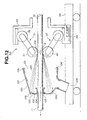
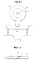
und das Verfahren weiterhin nach dem Schritt des Bewegens und bei dem Beginnen des Schleifschritts das Bewegen eines verfahrenden Schweissgeräts (4) in der Verfahrrichtung der gefügten Knüppel (10, 11) und synchron mit der Verfahrgeschwindigkeit der gefügten Knüppel umfasst. - Verfahren nach mindestens einem der vorhergehenden Ansprüche, weiterhin folgende Schritte umfassend:Streuen von durch Schleifen eines Grats auf einem geschweissten Abschnitt (10a) zweier Knüppel (10, 11) erzeugten Schleifspänen (120) zu einer stromabwärtigen Richtung der verfahrenden Knüppel und innerhalb einer beschränkten Richtung von der stromabwärtigen Richtung weg, wobei der Schritt des Streuens während des Bewegens einer verfahrenden Schleifmaschine (30) durchgeführt wird;Anordnen einer Haube (100) stromabwärts der verfahrenden Schleifmaschine (30), wobei die Haube der Streurichtung der Schleifspäne zugewendet ist;Ausbilden eines Wasserfilms (107) auf einer Innenfläche der Haube, indem Wasser entlang dieser Innenfläche abströmt; undSammeln der gestreuten Schleifspäne (120) mittels der Haube (100), damit die Schleifspäne kontinuierlich zusammen mit dem Wasserfilm abströmen.
- Verfahren nach Anspruch 8, dadurch gekennzeichnet, dass die Haube eine Öffnung (101, 103) zum Durchführen der Knüppel hierdurch und eine Knüppelabdeckung (104) bei der Öffnung (103) aufweist, um zu verhindern, dass die Knüppel dem Wasserfilm ausgesetzt sind.
- Schleifmaschine für ein Bandwalzverfahren von Knüppeln, umfassend:einen entlang der Verfahrrichtung der Knüppel (10, 11) pendelnden Verfahrkörper (54);eine durch den Verfahrkörper (54) getragene Trageinrichtung (55, 125);eine Vielzahl von relativ zur Trageinrichtung bewegbar befestigten Schleifeinrichtungen; undSchleifer (31, 32, 33; 41, 42, 43, 44) der Schleifeinrichtung;für Rundknüppel sind die Schleifer (31, 32, 33) relativ zur Verfahrrichtung des Knüppels in einer geneigten Richtung () eingestellt, oderfür Rechteckknüppel sind zwei Paare von Schleifern vorgesehen, wobei ein Paar (41, 44) von dem anderen (42, 43) entlang der Verfahrrichtung der Knüppel beabstandet ist.
- Schleifmaschine nach Anspruch 10, dadurch gekennzeichnet, dass die Trageinrichtung ein Revolverring (55) ist und in einem umlaufenden Zustand des Revolverrings durch den Verfahrkörper tragbar ist; und
die Schleifer (31, 32, 33; 41, 42, 43, 44) relativ zu einer Mittelachse des Revolverrings in einer geneigten Richtung (0) eingestellt sind. - Schleifmaschine nach Anspruch 10, dadurch gekennzeichnet, dass für Rechteckknüppel zwei Paare (51, 52) von Schleifeinrichtungen, wobei ein Paar an einer Vorderseite und das andere Paar an einer Hinterseite des Verfahrkörpers gelegen ist;eine Einrichtung (47, 48, 402, 56) zum Bewegen der Schleifeinrichtung in einer Richtung parallel zu dem Rechteckknüppel; undeine Einrichtung (46a, 46b, 46c) zum Veranlassen, dass die Schleifer sich auf den Rechteckknüppel zu und von ihm weg bewegen, vorgesehen sind.
- Schleifmaschine nach mindestens einem der Ansprüche 10 bis 12, weiterhin eine Staubsammelhaube (100) mit einer Wassersprühdüse (106) auf ihrer Innenseite umfassend.
- Schleifmaschine nach mindestens einem der Ansprüche 10 bis 13, weiterhin einen Sensor (90) zum Erfassen des Schweissabschnitts (10a) auf Knüppeln (10, 11) umfassend, wobei der Sensor stromaufwärts der Schleifeinrichtung (30, 51, 52) angeordnet ist.
Applications Claiming Priority (15)
| Application Number | Priority Date | Filing Date | Title |
|---|---|---|---|
| JP22314695 | 1995-08-31 | ||
| JP223401/95 | 1995-08-31 | ||
| JP22340195A JPH0966451A (ja) | 1995-08-31 | 1995-08-31 | 丸ビレット溶接部の走間バリ取り装置 |
| JP223146/95 | 1995-08-31 | ||
| JP22340195 | 1995-08-31 | ||
| JP22314695A JPH0966450A (ja) | 1995-08-31 | 1995-08-31 | フラッシュバット溶接部のバリ取り方法 |
| JP243313/95 | 1995-09-21 | ||
| JP24331395 | 1995-09-21 | ||
| JP07243313A JP3111867B2 (ja) | 1995-09-21 | 1995-09-21 | 走間研削機の制御方法 |
| JP282916/95 | 1995-10-31 | ||
| JP28291695A JP3198431B2 (ja) | 1995-10-31 | 1995-10-31 | 連続圧延における研削ノロの連続処理方法 |
| JP282917/95 | 1995-10-31 | ||
| JP28291795 | 1995-10-31 | ||
| JP28291695 | 1995-10-31 | ||
| JP28291795A JPH09122918A (ja) | 1995-10-31 | 1995-10-31 | 角ビレット溶接部のバリ取り装置 |
Publications (2)
| Publication Number | Publication Date |
|---|---|
| EP0761331A1 EP0761331A1 (de) | 1997-03-12 |
| EP0761331B1 true EP0761331B1 (de) | 2000-05-03 |
Family
ID=27529734
Family Applications (1)
| Application Number | Title | Priority Date | Filing Date |
|---|---|---|---|
| EP96113917A Expired - Lifetime EP0761331B1 (de) | 1995-08-31 | 1996-08-30 | Verfahren zur Beseitigung der Grate in einem kontinuierlichen Walzverfahren und Gerät dafür |
Country Status (4)
| Country | Link |
|---|---|
| US (1) | US5709585A (de) |
| EP (1) | EP0761331B1 (de) |
| AT (1) | ATE192363T1 (de) |
| DE (1) | DE69608051T2 (de) |
Cited By (3)
| Publication number | Priority date | Publication date | Assignee | Title |
|---|---|---|---|---|
| CN101829943A (zh) * | 2010-06-02 | 2010-09-15 | 常熟市中钛科技有限公司 | 核电站冷凝器用的钛管管坯修磨机 |
| CN105312978A (zh) * | 2015-12-11 | 2016-02-10 | 广州永大不锈钢有限公司 | 一种热轧不锈钢焊接管焊缝打磨方法及冷却控制方法 |
| CN105583703A (zh) * | 2015-12-11 | 2016-05-18 | 广州永大不锈钢有限公司 | 一种冷轧不锈钢焊接管焊缝打磨方法及冷却控制方法 |
Families Citing this family (13)
| Publication number | Priority date | Publication date | Assignee | Title |
|---|---|---|---|---|
| DE69633689T2 (de) | 1995-07-24 | 2005-03-10 | Jfe Steel Corp. | Gerät zum Oberflächenbearbeiten von heissgewalzten Stahlmaterialien |
| JPH11188484A (ja) * | 1997-12-25 | 1999-07-13 | Nkk Corp | 多段研削バリ取り装置 |
| IT1312424B1 (it) * | 1999-06-30 | 2002-04-17 | Techint Spa | Metodo ed impianto per la laminazione di una billetta continuaalimentata da un forno di riscaldo billette disposto a monte di un |
| US6627840B2 (en) * | 2001-03-09 | 2003-09-30 | Revelation Technologies, Llc | Method and means for processing butt welds |
| US7712651B2 (en) * | 2008-01-04 | 2010-05-11 | G. James Australia Pty. Ltd. | Method of welding heated log segments in an aluminum extrusion process |
| ITMI20100322A1 (it) * | 2010-02-26 | 2011-08-27 | Tecnopress S R L | Sgranatore automatico per fili metallici saldati. |
| EP2719498B1 (de) | 2012-10-12 | 2017-04-12 | Primetals Technologies Austria GmbH | Entgratvorrichtung mit Steuerungsmitteln zum drehbaren und zurück Fahren der Vorrichtung zur und weg von einer Stange |
| US9352423B2 (en) | 2013-03-13 | 2016-05-31 | Alcotec Wire Corporation | System and method for polishing and lubricating aluminum welding wire |
| US20170266775A1 (en) * | 2016-02-25 | 2017-09-21 | Manyo Co., Ltd. | Device for grinding end surfaces of billet |
| AT522610A1 (de) * | 2019-06-13 | 2020-12-15 | Mate Gmbh | Vorrichtung zur Nachbereitung von Rohrschweißnähten längs- oder spiralgeschweißter Rohre |
| CN112589580B (zh) * | 2020-12-07 | 2022-08-26 | 广东省优力高金属制品有限公司 | 一种金属线材打磨装置 |
| EP4335562A1 (de) * | 2022-09-08 | 2024-03-13 | David Teng Pong | Flash-schweissen für knüppel mit heruntergeschnittenen knüppelenden |
| GB202213171D0 (en) | 2022-09-08 | 2022-10-26 | Pong David Teng | Flash welding for billets with "down cut" billet ends |
Family Cites Families (13)
| Publication number | Priority date | Publication date | Assignee | Title |
|---|---|---|---|---|
| FR1130871A (fr) * | 1954-09-09 | 1957-02-13 | Licentia Gmbh | Dispositif d'assemblage, par soudage, de pièces allongées chaudes en une bande sans fin, sans interruption de l'opération consécutive de déformation |
| US2918759A (en) * | 1958-05-23 | 1959-12-29 | American Cyanamid Co | Planetary driven linear suture grinder |
| GB995125A (en) * | 1960-06-17 | 1965-06-16 | Bayliss Jones | Apparatus for cutting the surfaces of bars, billets and other articles |
| US3667165A (en) * | 1971-02-16 | 1972-06-06 | G & B Automated Equipment Ltd | Conditioning grinder |
| JPS5220492A (en) * | 1975-08-11 | 1977-02-16 | Nippon Steel Corp | Method of grinding round steel surface and apparatus thereof |
| JPS5237541A (en) * | 1975-09-19 | 1977-03-23 | Mitsubishi Electric Corp | Roll mill |
| JPS5243754A (en) * | 1975-10-03 | 1977-04-06 | Nippon Kokan Kk | Completely continuous steel rolling method |
| JPS5711722A (en) * | 1980-06-25 | 1982-01-21 | Daido Steel Co Ltd | Manufacturing apparatus for taper material |
| JPS5713361A (en) * | 1980-06-30 | 1982-01-23 | Komatsu Ltd | Self-correlation tachometer |
| DE3318865A1 (de) * | 1983-05-25 | 1984-11-29 | Mutz & Fornach GmbH & Co KG, 5840 Schwerte | Vorrichtung zum schleifen von insbesondere zylinderischen gegenstaenden mittels umlaufender schleifscheiben |
| DE3721488A1 (de) * | 1987-06-30 | 1989-01-12 | Ruth Domma Maschinenvertrieb | Verfahren und vorrichtung zum sicheren erkennen von graten an teilen im durchlaufverfahren |
| JP2985398B2 (ja) * | 1991-08-20 | 1999-11-29 | 富士電機株式会社 | 台間玉貸し機 |
| JPH05220492A (ja) * | 1992-02-12 | 1993-08-31 | Kubota Corp | 微生物固定化担体およびその製造方法 |
-
1996
- 1996-08-26 US US08/703,396 patent/US5709585A/en not_active Expired - Fee Related
- 1996-08-30 EP EP96113917A patent/EP0761331B1/de not_active Expired - Lifetime
- 1996-08-30 DE DE69608051T patent/DE69608051T2/de not_active Expired - Fee Related
- 1996-08-30 AT AT96113917T patent/ATE192363T1/de not_active IP Right Cessation
Cited By (4)
| Publication number | Priority date | Publication date | Assignee | Title |
|---|---|---|---|---|
| CN101829943A (zh) * | 2010-06-02 | 2010-09-15 | 常熟市中钛科技有限公司 | 核电站冷凝器用的钛管管坯修磨机 |
| CN105312978A (zh) * | 2015-12-11 | 2016-02-10 | 广州永大不锈钢有限公司 | 一种热轧不锈钢焊接管焊缝打磨方法及冷却控制方法 |
| CN105583703A (zh) * | 2015-12-11 | 2016-05-18 | 广州永大不锈钢有限公司 | 一种冷轧不锈钢焊接管焊缝打磨方法及冷却控制方法 |
| CN105583703B (zh) * | 2015-12-11 | 2017-12-15 | 广州永大不锈钢有限公司 | 一种冷轧不锈钢焊接管焊缝打磨方法 |
Also Published As
| Publication number | Publication date |
|---|---|
| EP0761331A1 (de) | 1997-03-12 |
| US5709585A (en) | 1998-01-20 |
| DE69608051D1 (de) | 2000-06-08 |
| DE69608051T2 (de) | 2000-10-26 |
| ATE192363T1 (de) | 2000-05-15 |
Similar Documents
| Publication | Publication Date | Title |
|---|---|---|
| EP0761331B1 (de) | Verfahren zur Beseitigung der Grate in einem kontinuierlichen Walzverfahren und Gerät dafür | |
| US6195859B1 (en) | Surface cutting apparatus for hot-rolled steel products | |
| US4626647A (en) | Flash welding machine | |
| KR970009909A (ko) | 연속압연방법 | |
| KR100213576B1 (ko) | 연속 압연 방법과 그에 대한 장치 | |
| EP0761330A1 (de) | Verfahren und Anlage zum kontinuierlichen Walzen | |
| EP0761329B1 (de) | Vorrichtung zum Verbinden von Knüppeln in einem kontinuierlichen Walzwerk | |
| GB2084494A (en) | Grinding faces of continuously cast steel | |
| CN1034634C (zh) | 用于支承轧边机中板坯的压紧辊 | |
| EP0815968B1 (de) | Verfahren und Vorrichtung zum kontinuierlichen Walzen | |
| JPH09122918A (ja) | 角ビレット溶接部のバリ取り装置 | |
| KR200174706Y1 (ko) | 불량 냉연코일의 자동 제거장치 | |
| KR200220533Y1 (ko) | 강판용접부 표면의 러스트 자동제거장치 | |
| JPH0966451A (ja) | 丸ビレット溶接部の走間バリ取り装置 | |
| JP3111867B2 (ja) | 走間研削機の制御方法 | |
| SU1090515A1 (ru) | Станок дл профилировани рельсовых стыков после сварки | |
| KR100868501B1 (ko) | 압연기 작업롤의 표면 이물 제거장치 | |
| JP3674719B2 (ja) | パス切替装置を有する圧延材接合装置 | |
| CN117677448A (zh) | 用于加工由非铁金属制成的连续的带材材料的至少一个表面的设备和方法 | |
| KR950014304B1 (ko) | 아연도금강판 생산라인의 용접구 자동 통과장치 | |
| JPS62220296A (ja) | レ−ザ加工装置 | |
| JPH0561004B2 (de) | ||
| WO1984000916A1 (en) | Device and method for grinding in connection with the manufacture of rolled products | |
| JPH10337665A (ja) | 研削砥石の周速制御方法 | |
| JPH10192902A (ja) | 圧延機間溶接式連続圧延法及びその装置 |
Legal Events
| Date | Code | Title | Description |
|---|---|---|---|
| PUAI | Public reference made under article 153(3) epc to a published international application that has entered the european phase |
Free format text: ORIGINAL CODE: 0009012 |
|
| 17P | Request for examination filed |
Effective date: 19960830 |
|
| AK | Designated contracting states |
Kind code of ref document: A1 Designated state(s): AT DE FR GB IT |
|
| 17Q | First examination report despatched |
Effective date: 19981016 |
|
| GRAG | Despatch of communication of intention to grant |
Free format text: ORIGINAL CODE: EPIDOS AGRA |
|
| GRAG | Despatch of communication of intention to grant |
Free format text: ORIGINAL CODE: EPIDOS AGRA |
|
| GRAH | Despatch of communication of intention to grant a patent |
Free format text: ORIGINAL CODE: EPIDOS IGRA |
|
| GRAG | Despatch of communication of intention to grant |
Free format text: ORIGINAL CODE: EPIDOS AGRA |
|
| GRAH | Despatch of communication of intention to grant a patent |
Free format text: ORIGINAL CODE: EPIDOS IGRA |
|
| GRAA | (expected) grant |
Free format text: ORIGINAL CODE: 0009210 |
|
| AK | Designated contracting states |
Kind code of ref document: B1 Designated state(s): AT DE FR GB IT |
|
| REF | Corresponds to: |
Ref document number: 192363 Country of ref document: AT Date of ref document: 20000515 Kind code of ref document: T |
|
| REF | Corresponds to: |
Ref document number: 69608051 Country of ref document: DE Date of ref document: 20000608 |
|
| ITF | It: translation for a ep patent filed |
Owner name: BUGNION S.P.A. |
|
| ET | Fr: translation filed | ||
| PLBE | No opposition filed within time limit |
Free format text: ORIGINAL CODE: 0009261 |
|
| STAA | Information on the status of an ep patent application or granted ep patent |
Free format text: STATUS: NO OPPOSITION FILED WITHIN TIME LIMIT |
|
| 26N | No opposition filed | ||
| PGFP | Annual fee paid to national office [announced via postgrant information from national office to epo] |
Ref country code: FR Payment date: 20010810 Year of fee payment: 6 |
|
| PGFP | Annual fee paid to national office [announced via postgrant information from national office to epo] |
Ref country code: AT Payment date: 20010813 Year of fee payment: 6 |
|
| PGFP | Annual fee paid to national office [announced via postgrant information from national office to epo] |
Ref country code: DE Payment date: 20010820 Year of fee payment: 6 |
|
| PGFP | Annual fee paid to national office [announced via postgrant information from national office to epo] |
Ref country code: GB Payment date: 20010830 Year of fee payment: 6 |
|
| REG | Reference to a national code |
Ref country code: GB Ref legal event code: IF02 |
|
| PG25 | Lapsed in a contracting state [announced via postgrant information from national office to epo] |
Ref country code: GB Free format text: LAPSE BECAUSE OF NON-PAYMENT OF DUE FEES Effective date: 20020830 Ref country code: AT Free format text: LAPSE BECAUSE OF NON-PAYMENT OF DUE FEES Effective date: 20020830 |
|
| PG25 | Lapsed in a contracting state [announced via postgrant information from national office to epo] |
Ref country code: DE Free format text: LAPSE BECAUSE OF NON-PAYMENT OF DUE FEES Effective date: 20030301 |
|
| GBPC | Gb: european patent ceased through non-payment of renewal fee |
Effective date: 20020830 |
|
| PG25 | Lapsed in a contracting state [announced via postgrant information from national office to epo] |
Ref country code: FR Free format text: LAPSE BECAUSE OF NON-PAYMENT OF DUE FEES Effective date: 20030430 |
|
| REG | Reference to a national code |
Ref country code: FR Ref legal event code: ST |
|
| PG25 | Lapsed in a contracting state [announced via postgrant information from national office to epo] |
Ref country code: IT Free format text: LAPSE BECAUSE OF NON-PAYMENT OF DUE FEES;WARNING: LAPSES OF ITALIAN PATENTS WITH EFFECTIVE DATE BEFORE 2007 MAY HAVE OCCURRED AT ANY TIME BEFORE 2007. THE CORRECT EFFECTIVE DATE MAY BE DIFFERENT FROM THE ONE RECORDED. Effective date: 20050830 |