EP0761316A2 - Klebstoffauftragsvorrichtung - Google Patents
Klebstoffauftragsvorrichtung Download PDFInfo
- Publication number
- EP0761316A2 EP0761316A2 EP96111225A EP96111225A EP0761316A2 EP 0761316 A2 EP0761316 A2 EP 0761316A2 EP 96111225 A EP96111225 A EP 96111225A EP 96111225 A EP96111225 A EP 96111225A EP 0761316 A2 EP0761316 A2 EP 0761316A2
- Authority
- EP
- European Patent Office
- Prior art keywords
- adhesive
- roller
- chamber
- side wall
- adhesive application
- Prior art date
- Legal status (The legal status is an assumption and is not a legal conclusion. Google has not performed a legal analysis and makes no representation as to the accuracy of the status listed.)
- Granted
Links
- 239000003292 glue Substances 0.000 title claims description 18
- 239000000853 adhesive Substances 0.000 claims abstract description 98
- 230000001070 adhesive effect Effects 0.000 claims abstract description 98
- 238000007789 sealing Methods 0.000 claims abstract description 20
- 239000013013 elastic material Substances 0.000 claims abstract description 4
- 239000013536 elastomeric material Substances 0.000 claims description 2
- 230000035508 accumulation Effects 0.000 abstract description 3
- 238000009825 accumulation Methods 0.000 abstract description 3
- 239000002313 adhesive film Substances 0.000 description 4
- 230000002706 hydrostatic effect Effects 0.000 description 2
- 238000007599 discharging Methods 0.000 description 1
- 230000000694 effects Effects 0.000 description 1
- 239000004744 fabric Substances 0.000 description 1
- 239000012530 fluid Substances 0.000 description 1
- 238000009499 grossing Methods 0.000 description 1
- 239000007788 liquid Substances 0.000 description 1
- 239000000463 material Substances 0.000 description 1
- 230000002093 peripheral effect Effects 0.000 description 1
- 239000004753 textile Substances 0.000 description 1
- 239000010409 thin film Substances 0.000 description 1
Images

Classifications
-
- B—PERFORMING OPERATIONS; TRANSPORTING
- B05—SPRAYING OR ATOMISING IN GENERAL; APPLYING FLUENT MATERIALS TO SURFACES, IN GENERAL
- B05C—APPARATUS FOR APPLYING FLUENT MATERIALS TO SURFACES, IN GENERAL
- B05C1/00—Apparatus in which liquid or other fluent material is applied to the surface of the work by contact with a member carrying the liquid or other fluent material, e.g. a porous member loaded with a liquid to be applied as a coating
- B05C1/04—Apparatus in which liquid or other fluent material is applied to the surface of the work by contact with a member carrying the liquid or other fluent material, e.g. a porous member loaded with a liquid to be applied as a coating for applying liquid or other fluent material to work of indefinite length
- B05C1/08—Apparatus in which liquid or other fluent material is applied to the surface of the work by contact with a member carrying the liquid or other fluent material, e.g. a porous member loaded with a liquid to be applied as a coating for applying liquid or other fluent material to work of indefinite length using a roller or other rotating member which contacts the work along a generating line
- B05C1/086—Apparatus in which liquid or other fluent material is applied to the surface of the work by contact with a member carrying the liquid or other fluent material, e.g. a porous member loaded with a liquid to be applied as a coating for applying liquid or other fluent material to work of indefinite length using a roller or other rotating member which contacts the work along a generating line a pool of coating material being formed between a roller, e.g. a dosing roller and an element cooperating therewith
- B05C1/0865—Apparatus in which liquid or other fluent material is applied to the surface of the work by contact with a member carrying the liquid or other fluent material, e.g. a porous member loaded with a liquid to be applied as a coating for applying liquid or other fluent material to work of indefinite length using a roller or other rotating member which contacts the work along a generating line a pool of coating material being formed between a roller, e.g. a dosing roller and an element cooperating therewith the cooperating element being a roller, e.g. a coating roller
-
- B—PERFORMING OPERATIONS; TRANSPORTING
- B05—SPRAYING OR ATOMISING IN GENERAL; APPLYING FLUENT MATERIALS TO SURFACES, IN GENERAL
- B05C—APPARATUS FOR APPLYING FLUENT MATERIALS TO SURFACES, IN GENERAL
- B05C1/00—Apparatus in which liquid or other fluent material is applied to the surface of the work by contact with a member carrying the liquid or other fluent material, e.g. a porous member loaded with a liquid to be applied as a coating
- B05C1/04—Apparatus in which liquid or other fluent material is applied to the surface of the work by contact with a member carrying the liquid or other fluent material, e.g. a porous member loaded with a liquid to be applied as a coating for applying liquid or other fluent material to work of indefinite length
- B05C1/08—Apparatus in which liquid or other fluent material is applied to the surface of the work by contact with a member carrying the liquid or other fluent material, e.g. a porous member loaded with a liquid to be applied as a coating for applying liquid or other fluent material to work of indefinite length using a roller or other rotating member which contacts the work along a generating line
- B05C1/086—Apparatus in which liquid or other fluent material is applied to the surface of the work by contact with a member carrying the liquid or other fluent material, e.g. a porous member loaded with a liquid to be applied as a coating for applying liquid or other fluent material to work of indefinite length using a roller or other rotating member which contacts the work along a generating line a pool of coating material being formed between a roller, e.g. a dosing roller and an element cooperating therewith
-
- B—PERFORMING OPERATIONS; TRANSPORTING
- B05—SPRAYING OR ATOMISING IN GENERAL; APPLYING FLUENT MATERIALS TO SURFACES, IN GENERAL
- B05C—APPARATUS FOR APPLYING FLUENT MATERIALS TO SURFACES, IN GENERAL
- B05C1/00—Apparatus in which liquid or other fluent material is applied to the surface of the work by contact with a member carrying the liquid or other fluent material, e.g. a porous member loaded with a liquid to be applied as a coating
- B05C1/04—Apparatus in which liquid or other fluent material is applied to the surface of the work by contact with a member carrying the liquid or other fluent material, e.g. a porous member loaded with a liquid to be applied as a coating for applying liquid or other fluent material to work of indefinite length
- B05C1/08—Apparatus in which liquid or other fluent material is applied to the surface of the work by contact with a member carrying the liquid or other fluent material, e.g. a porous member loaded with a liquid to be applied as a coating for applying liquid or other fluent material to work of indefinite length using a roller or other rotating member which contacts the work along a generating line
- B05C1/0813—Apparatus in which liquid or other fluent material is applied to the surface of the work by contact with a member carrying the liquid or other fluent material, e.g. a porous member loaded with a liquid to be applied as a coating for applying liquid or other fluent material to work of indefinite length using a roller or other rotating member which contacts the work along a generating line characterised by means for supplying liquid or other fluent material to the roller
-
- B—PERFORMING OPERATIONS; TRANSPORTING
- B05—SPRAYING OR ATOMISING IN GENERAL; APPLYING FLUENT MATERIALS TO SURFACES, IN GENERAL
- B05C—APPARATUS FOR APPLYING FLUENT MATERIALS TO SURFACES, IN GENERAL
- B05C1/00—Apparatus in which liquid or other fluent material is applied to the surface of the work by contact with a member carrying the liquid or other fluent material, e.g. a porous member loaded with a liquid to be applied as a coating
- B05C1/04—Apparatus in which liquid or other fluent material is applied to the surface of the work by contact with a member carrying the liquid or other fluent material, e.g. a porous member loaded with a liquid to be applied as a coating for applying liquid or other fluent material to work of indefinite length
- B05C1/08—Apparatus in which liquid or other fluent material is applied to the surface of the work by contact with a member carrying the liquid or other fluent material, e.g. a porous member loaded with a liquid to be applied as a coating for applying liquid or other fluent material to work of indefinite length using a roller or other rotating member which contacts the work along a generating line
- B05C1/0826—Apparatus in which liquid or other fluent material is applied to the surface of the work by contact with a member carrying the liquid or other fluent material, e.g. a porous member loaded with a liquid to be applied as a coating for applying liquid or other fluent material to work of indefinite length using a roller or other rotating member which contacts the work along a generating line the work being a web or sheets
- B05C1/083—Apparatus in which liquid or other fluent material is applied to the surface of the work by contact with a member carrying the liquid or other fluent material, e.g. a porous member loaded with a liquid to be applied as a coating for applying liquid or other fluent material to work of indefinite length using a roller or other rotating member which contacts the work along a generating line the work being a web or sheets being passed between the coating roller and one or more backing rollers
-
- B—PERFORMING OPERATIONS; TRANSPORTING
- B05—SPRAYING OR ATOMISING IN GENERAL; APPLYING FLUENT MATERIALS TO SURFACES, IN GENERAL
- B05D—PROCESSES FOR APPLYING FLUENT MATERIALS TO SURFACES, IN GENERAL
- B05D5/00—Processes for applying liquids or other fluent materials to surfaces to obtain special surface effects, finishes or structures
- B05D5/10—Processes for applying liquids or other fluent materials to surfaces to obtain special surface effects, finishes or structures to obtain an adhesive surface
-
- Y—GENERAL TAGGING OF NEW TECHNOLOGICAL DEVELOPMENTS; GENERAL TAGGING OF CROSS-SECTIONAL TECHNOLOGIES SPANNING OVER SEVERAL SECTIONS OF THE IPC; TECHNICAL SUBJECTS COVERED BY FORMER USPC CROSS-REFERENCE ART COLLECTIONS [XRACs] AND DIGESTS
- Y10—TECHNICAL SUBJECTS COVERED BY FORMER USPC
- Y10T—TECHNICAL SUBJECTS COVERED BY FORMER US CLASSIFICATION
- Y10T156/00—Adhesive bonding and miscellaneous chemical manufacture
- Y10T156/17—Surface bonding means and/or assemblymeans with work feeding or handling means
- Y10T156/1798—Surface bonding means and/or assemblymeans with work feeding or handling means with liquid adhesive or adhesive activator applying means
Definitions
- the invention relates to an adhesive application device with an adhesive-receiving chamber, the front side of which is bounded by an adhesive roller with a vertical axis of rotation, which with a vertical side wall of the chamber delimits a return gap for adhesive orders that have not been removed, and is closed by a sealing roller that is parallel to the latter and joins the adhesive application roller
- Adhesive passage gap forms and is sealed by sealing means against the other vertical side wall of the chamber, and with a glue applicator roller which can be placed on the adhesive roller and which preferably takes format-based adhesive orders from it and transfers them to workpieces to be glued.
- an adhesive application device with an adhesive receiving chamber is known, the front vertical opening side of which is closed by an adhesive roller with a vertical axis of rotation and a sealing roller arranged laterally therefrom, which are driven in opposite directions to the adhesive roller at a higher peripheral speed, limit with this adhesive passage gaps and are sealed against the vertical side walls of the chamber by doctor blades attached to them.
- the lateral sealing rollers on the one hand delimit an exit gap, so that there is contact with the adhesive roller
- Adhesive film of the desired thickness can form, and on the other hand an entry gap, which prevents that not removed adhesive jams and flows off in an uncontrollable manner.
- the doctor blades are sealingly placed on the two sealing rollers so that there is no gap from which adhesive could escape from the storage container.
- the vertical open side of the glue chamber is closed only by the adhesive roller and a sealing roller, which leads to a certain structural simplification.
- the sealing roller can in turn be sealed off from the second vertical side wall of the adhesive chamber by a doctor blade attached to it.
- the problem with this known device is the return gap for non-removed adhesive applications between the adhesive roller and the vertical edge of the first side wall of the adhesive chamber, because the rotating rollers in the adhesive chamber can cause pressure-increasing vortices which lead to adhesive in front of the return gap jams and flows away in an undesirable manner, which can lead to annoying soiling of machine and system parts.
- the object of the invention is therefore to provide an adhesive application device of the type specified in the introduction, in which accumulations of adhesive tending to uncontrolled outflow are avoided in front of the return gap.
- this object is achieved in that a strip of flexible and / or elastic material is attached to the side wall delimiting the return gap, and its free end bears against the jacket region of the adhesive roller entering the chamber.
- This strip provided according to the invention forms, as it were, an apron which prevents the internal pressure of the glue chamber from reacting to the return gap in such a way that undesirable and tendency to run away adhesive accumulations form in front of the latter.
- the strip basically only needs to lie loosely on the jacket of the adhesive roller because it is, as it were, sucked into the jacket of the rotating adhesive application roller by its jacket.
- the returned adhesive enters in the form of a thin film between the strip and the adhesive roller in the glue chamber in an area behind the return gap, so that an undesirable reaction is excluded.
- the strip not only smoothes the returned flow of the adhesive that has not been removed, it also prevents turbulence in the area of the return gap, since this is protected and covered by the strip.
- the strip can be made of elastomeric material or a cloth made of textile material.
- the strip expediently widens starting from the upper side of the chamber towards the bottom thereof, as a result of which the hydrostatic pressure of the adhesive, which increases towards the bottom, is taken into account.
- the device according to the invention not only works when the adhesive chamber and the rollers are arranged vertically, but the front open side of the chamber can also be at the top, in which case the adhesive roller, the sealing roller and the adhesive application roller accordingly have horizontal axes of rotation.
- the known device consists of a U-shaped housing 1 forming the side walls and the rear wall of the glue chamber, which is closed by bottom and top walls.
- a strip 3 is connected to the left vertical side wall 2 of the adhesive chamber 1, the end face of which is curved in accordance with the radius of curvature of the adhesive roller 4 and forms a return gap 5 for adhesive that has not been removed.
- the bar 3 can be moved parallel to the front edge of the side wall 2 of the glue chamber 1 and fixed in predetermined positions.
- the adhesive roller 4 is driven to rotate about its vertical axis in the direction of arrow A.
- a sealing roller 6 In parallel to the adhesive roller 4, a sealing roller 6 is also provided which can be rotated about a vertical axis and which rotates in the same direction as the adhesive roller, as indicated by the arrow. To drive the adhesive roller and the sealing roller 6, a belt pulley or a toothed belt pulley 7 is provided, over which a belt 8 runs, which drives the belt pulleys of the rollers 4, 6.
- the sealing roller 6 forms with the adhesive roller 4 a gap 9 of adjustable width, through which the thickness of the adhesive film entrained by the adhesive roller can be adjusted.
- An adhesive application roller 10 which also rotates around a vertical axis, can be placed on the adhesive roller 4 and is provided with corresponding adhesive application segments on its jacket for the transfer of format adhesive applications, which segments are not shown in the drawing.
- a gap 11 is provided between the sealing roller 6 and the adhesive application roller 10 such that the two do not touch one another.
- an adjustable doctor blade 13 is attached, which doctor the adhesive from the sealing roller 6, so that it carries no adhesive to the outside.
- the adhesive Due to the rotation, in particular, of the adhesive roller 4 and also of the sealing roller 6, the adhesive is set into a swirling, rotating movement in the adhesive chamber 1 filled with adhesive, which is indicated in FIG. 2 by the arrows 15. Because of this turbulence and the pressure prevailing in the adhesive chamber, the trouble-free return of the adhesive not removed from the adhesive roller by the adhesive application roller can be hindered, so that this accumulates in front of the return gap 5 and an undesired outflow of adhesive can occur.
- the adhesive application device according to the invention will now be described with reference to FIGS. 1 and 3, the device according to the invention basically being constructed in the same way as that described with reference to FIG. 2, so that the identical parts are not explained again.
- the device according to the invention differs from the known essentially only in that between the vertical left side wall 2 of the adhesive chamber 1 and the strip 3 delimiting the return gap 5, a strip 16 of flexible and / or elastic material is fastened, which in the manner shown bears against a region of the jacket of the adhesive roller within the chamber 1 filled with glue.
- the strip 16 prevents the liquid pressure of the glue from acting directly on the return gap 5 within the glue chamber 1, so that an unimpeded entry of the adhesive film which has not been removed and returned is ensured.
- the rollers closing the front of the adhesive chamber 1 essentially only produce a smaller vortex 17, which, however, does not act directly on the return gap 5 due to the skirt-like strip 6.
- the result is that the adhesive film returned through the return gap 5 can enter completely and without hindrance through the return gap 5 and experience a smoothing effect before it combines again with the adhesive located in the adhesive chamber.
- the glue chamber 1 is provided in its lower region with an opening 20 for supplying the glue and an opening 21 for discharging the glue.
- the strip 16 widens from its lower end towards the bottom of the glue chamber 1, as is indicated by the broken line 22.
- the adhesive roller 4 and the sealing roller 6 are provided with upper shaft journals 23, 24 which, as indicated schematically, are mounted in an upper bearing plate 25.
Landscapes
- Coating Apparatus (AREA)
- Application Of Or Painting With Fluid Materials (AREA)
- Adhesive Tapes (AREA)
- Formation And Processing Of Food Products (AREA)
- Seal Device For Vehicle (AREA)
- Polarising Elements (AREA)
- Manufacturing Of Electric Cables (AREA)
Abstract
Description
- Die Erfindung betrifft eine Klebstoffauftragsvorrichtung mit einer Klebstoff aufnehmenden Kammer, deren vordere Seite durch eine Klebstoffwalze mit vertikaler Drehachse, die mit einer vertikalen Seitenwand der Kammer einen Rückförderspalt für nicht abgenommene Klebstoffaufträge begrenzt und durch eine zu dieser parallele Dichtwalze geschlossen ist, die mit der Klebstoffauftragswalze einen Klebstoffdurchtrittsspalt bildet und durch Abdichtmittel gegenüber der anderen vertikalen Seitenwand der Kammer abgedichtet ist, und mit einer an die Klebstoffwalze anstellbaren Leimauftragswalze, die vorzugsweise formatmäßige Leimaufträge von dieser übernimmt und auf zu beleimende Werkstücke überträgt.
- Aus der DE-PS 29 48 745 ist eine Klebstoffauftragsvorrichtung mit einer Klebstoff aufnehmenden Kammer bekannt, deren vordere vertikale Öffnungsseite durch eine Klebstoffwalze mit vertikaler Drehachse und je einer seitlich von dieser angeordneten Dichtungswalze geschlossen ist, die gegenläufig zu der Klebstoffwalze mit höherer Umfangsgeschwindigkeit angetrieben sind, mit dieser Klebstoffdurchtrittsspalte begrenzen und gegenüber den vertikalen Seitenwandungen der Kammer durch an diesen befestigte Rakeln abgedichtet sind. Bei dieser bekannten Klebstoffauftragsvorrichtung begrenzen die seitlichen Abdichtungswalzen einerseits einen Austrittsspalt, so daß sich auf der Klebstoffwalze ein Klebstoffilm der gewünschten Dicke ausbilden kann, und andererseits einen Eintrittsspalt, der verhindert, daß sich nicht abgenommener Klebstoff staut und in unkontrollierbarer Weise abfließt. Die Rakeln sind dichtend an die beiden Abdichtungswalzen angestellt, so daß kein Spalt verbleibt, aus dem Klebstoff aus dem Vorratsbehälter austreten könnte.
- Bei einer aus der Praxis bekannten Klebstoffauftragsvorrichtung der eingangs angegebenen Art ist die vertikale offene Seite der Leimkammer nur durch die Klebstoffwalze und eine Dichtwalze geschlossen, was zu einer gewissen baulichen Vereinfachung führt. Die Dichtwalze kann wiederum gegenüber der zweiten vertikalen Seitenwand der Klebstoffkammer durch eine an dieser befestigte Rakel abgedichtet sein. Problematisch ist jedoch bei dieser bekannten Vorrichtung der Rückförderspalt für nicht abgenommene Klebstoffaufträge zwischen der Klebstoffwalze und der vertikalen Kante der ersten Seitenwand der Klebstoffkammer, weil sich aufgrund der rotierenden Walzen in der Klebstoffkammer druckerhöhende Wirbel ausbilden können, die dazu führen, daß sich vor dem Rückförderspalt Klebstoff staut und in unerwünschter Weise abfließt, was zu lästigen Verschmutzungen von Maschinen- und Anlagenteilen führen kann.
- Aufgabe der Erfindung ist es daher, eine Klebstoffauftragsvorrichtung der eingangs angegebenen Art zu schaffen, bei der zu einem unkontrollierten Abfließen neigende Klebstoffansammlungen vor dem Rückförderspalt vermieden sind.
- Erfindungsgemäß wird diese Aufgabe dadurch gelöst, daß an der den Rückförderspalt begrenzenden Seitenwand ein Streifen aus flexiblem und/oder elastischem Material befestigt ist, der sich mit seinem freien Ende an den in die Kammer einlaufenden Mantelbereich der Klebstoffwalze anlegt.
- Dieser erfindungsgemäß vorgesehene Streifen bildet gleichsam eine Schürze, die eine Rückwirkung des Innendrucks der Leimkammer auf den Rückförderspalt in der Weise verhindert, daß sich unerwünschte und zum Abfließen neigende Klebstoffansammlungen vor diesem ausbilden. Der Streifen braucht grundsätzlich nur lose an dem Mantel der Klebstoffwalze anzuliegen, weil er durch die hydrodynamische Wirkung der rotierenden Klebstoffauftragswalze an deren Mantel gleichsam angesaugt wird. Der zurückgeförderte Klebstoff tritt in Form eines dünnen Films zwischen dem Streifen und der Klebstoffwalze in die Leimkammer in einem Bereich hinter dem Rückförderspalt ein, so daß eine unerwünschte Rückwirkung ausgeschlossen ist. Der Streifen führt nicht nur zu einer Glättung des zurückgeförderten Stroms des nicht abgenommenen Klebstoffs, er verhindert auch Turbulenzen im Bereich des Rückförderspalts, da dieser durch den Streifen geschützt und abgedeckt ist.
- Der Streifen kann aus elastomerem Material oder aber auch aus einem Tuch aus textilem Material bestehen.
- Zweckmäßigerweise verbreitert sich der Streifen ausgehend von der oberen Seite der Kammer zu deren Boden hin, wodurch dem nach unten hin zunehmenden hydrostatischen Druck des Klebstoffs Rechnung getragen wird.
- Die erfindungsgemäße Vorrichtung arbeitet nicht nur bei vertikaler Anordnung der Klebstoffkammer und der Walzen, sondern die vordere offene Seite der Kammer kann auch oben liegen, wobei dann die Klebstoffwalze, die Dichtwalze und die Klebstoffauftragswalze dementsprechend horizontale Drehachsen besitzen.
- Ein Ausführungsbeispiel der Erfindung wird nachstehend anhand der Zeichnung näher beschrieben. In dieser zeigt
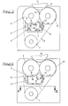
- Fig. 1
- eine Draufsicht auf die erfindungsgemäße Leimauftragsvorrichtung in schematischer Darstellung,
- Fig. 2
- eine Draufsicht auf eine bekannte Leimauftragsvorrichtung und
- Fig. 3
- eine Seitenansicht der Leimauftragssvorrichtung in der Schnittebene III-III in Fig. 1.
- Aus Fig. 2 ist eine Draufsicht auf eine bekannte Klebstoffauftragsvorrichtung ersichtlich, bei der zur besseren Übersichtlichkeit die Lagerplatte für die Walze und die obere Deckplatte der Klebstoffkammer entfernt sind. Die bekannte Vorrichtung besteht aus einem die Seitenwände und die Rückwand der Leimkammer bildenden U-förmigen Gehäuse 1, das durch Boden- und Deckwände geschlossen ist. Mit der linken vertikalen Seitenwand 2 der Klebstoffkammer 1 ist eine Leiste 3 verbunden, deren Stirnseite entsprechend dem Krümmungsradius der Klebstoffwalze 4 gekrümmt ist und mit dieser einen Rückförderspalt 5 für nicht abgenommenen Klebstoff bildet. Zur Einstellung der Breite des Rückförderspalts 5 läßt sich die Leiste 3 parallel zur Vorderkante der Seitenwand 2 der Leimkammer 1 bewegen und in vorbestimmten Stellungen fixieren. Die Klebstoffwalze 4 ist rotierend um ihre vertikale Achse in Richtung des Pfeils A angetrieben. Parallel zu der Klebstoffwalze 4 ist ebenfalls eine um eine vertikale Achse drehbare Dichtungswalze 6 vorgesehen, die gleichsinnig wie die Klebstoffwalze rotiert, wie durch den Pfeil angedeutet ist. Zum Antrieb der Klebstoffwalze und der Dichtungswalze 6 ist eine Riemenscheibe oder eine Zahnriemenscheibe 7 vorgesehen, über die ein Riemen 8 läuft, der die Riemenscheiben der Walzen 4, 6 antreibt.
- Die Dichtungswalze 6 bildet mit der Klebstoffwalze 4 einen Spalt 9 einstellbarer Breite, durch den sich die Dicke des von der Klebstoffwalze mitgenommenen Klebstoffilms einstellen läßt.
- An die Klebstoffwalze 4 ist eine ebenfalls um eine vertikale Achse umlaufende Klebstoffauftragswalze 10 anstellbar, die auf ihrem Mantel zur Übertragung von formatmäßigen Leimaufträgen mit entsprechenden Leimauftragssegmenten versehen ist, die in der Zeichnung nicht dargestellt sind. Zwischen der Dichtungswalze 6 und der Klebstoffauftragswalze 10 ist ein so großer Spalt 11 vorgesehen, daß beide einander nicht berühren. An der rechten vertikalen Seitenwand 12 der Klebstoffkammer 1 ist ein einstellbares Rakelmesser 13 befestigt, das den Klebstoff von der Dichtungswalze 6 abrakelt, so daß diese keinen Klebstoff nach außen trägt.
- Aufgrund der Rotation insbesondere der Klebstoffwalze 4 und auch der Dichtungswalze 6 wird der Klebstoff in der mit Klebstoff gefüllten Klebstoffkammer 1 in eine wirbelnde, drehende Bewegung versetzt, die in Fig. 2 durch die Pfeile 15 angedeutet ist. Aufgrund dieser Verwirbelung und des in der Klebstoffkammer herrschenden Drucks kann die störungsfreie Rückförderung des nicht von der Klebstoffwalze durch die Klebstoffauftragswalze abgenommenen Klebstoffs behindert sein, so daß sich dieser vor dem Rückförderspalt 5 stauen und es zu einem unerwünschten Abfließen von Klebstoff kommen kann.
- Die erfindungsgemäße Klebstoffauftragsvorrichtung wird nun anhand der Fig. 1 und 3 beschrieben, wobei die erfindungsgemäße Vorrichtung grundsätzlich gleich aufgebaut ist wie die anhand der Fig. 2 beschriebene, so daß die identischen Teile nicht nochmals erläutert werden. Die erfindungsgemäße Vorrichtung unterscheidet sich von der bekannten im wesentlichen nur dadurch, daß zwischen der vertikalen linken Seitenwand 2 der Klebstoffkammer 1 und der den Rückförderspalt 5 begrenzenden Leiste 3 ein Streifen 16 aus flexiblem und/oder elastischem Material befestigt ist, der sich in der dargestellten Weise gegen einen Bereich des Mantels der Klebstoffwalze innerhalb der mit Leim gefüllten Kammer 1 anlegt. Der Streifen 16 verhindert, daß der Flüssigkeitsdruck des Leims innerhalb der Leimkammer 1 unmittelbar auf den Rückförderspalt 5 einwirkt, so daß ein behinderungsfreier Einlauf des nicht abgenommenen und rückgeförderten Klebstoffilms gesichert ist. Die die Vorderseite der Klebstoffkammer 1 schliessenden Walzen erzeugen im wesentlichen nur noch einen kleineren Wirbel 17, der aber aufgrund des schürzenartigen Streifens 6 unmittelbar nicht auf den Rückförderspalt 5 einwirkt. Die Folge ist, daß der durch den Rückförderspalt 5 zurückgeförderte Klebstoffilm vollständig und behinderungsfrei durch den Rückförderspalt 5 eintreten kann und eine Glättungswirkung erfährt, bevor er sich wieder mit dem in der Klebstoffkammer befindlichen Klebstoff vereinigt.
- Wie aus Fig. 3 ersichtlich ist, ist die Leimkammer 1 in ihrem unteren Bereich mit einer Öffnung 20 zur Zuführung des Leims und einer Öffnung 21 zur Abführung des Leims versehen. Entsprechend der Zunahme des hydrostatischen Flüssigkeitsdrucks verbreitert sich der Streifen 16 von seinem unteren Ende in Richtung auf den Boden der Leimkammer 1, wie es durch die gestrichtelte Linie 22 angedeutet ist. Die Klebstoffwalze 4 und die Abdichtungswalze 6 sind mit oberen Wellenzapfen 23, 24 versehen, die, wie schematisch angedeutet, in einer oberen Lagerplatte 25 gelagert sind.
Claims (4)
- Klebstoffauftragsvorrichtung
mit einer Klebstoff aufnehmenden Klebstoffkammer, deren vordere Seite durch eine Klebstoffwalze mit vertikaler Drehachse, die mit einer vertikalen Seitenwand der Kammer einen Rückförderspalt für nicht abgenommene Klebstoffaufträge begrenzt, und durch zu dieser parallele Dichtungswalze geschlossen ist, die mit der Klebstoffauftragswalze einen Klebstoffdurchtrittsspalt bildet und durch Abdichtmittel gegenüber der anderen vertikalen Seitenwand der Kammer abgedichtet ist, und mit einer an die Klebstoffwalze anstellbaren Klebstoffauftragswalze, die vorzugsweise formatmäßige Leimaufträge von dieser übernimmt und auf mit einem Klebstoffauftrag zu versehende Werkstücke überträgt,
dadurch gekennzeichnet,
daß an der den Rückförderspalt begrenzenden Seitenwand ein Streifen aus flexiblem und/oder elastischem Material befestigt ist, der sich mit seinem freien Teil an den die Kammer einlaufenden Mantelbereich der Klebstoffwalze anlegt. - Klebstoffauftragsvorrichtung nach Anspruch 1, dadurch gekennzeichnet, daß der Streifen aus elastomerem Material besteht.
- Klebstoffauftragsvorrichtung nach Anspruch 1 oder 2, dadurch gekennzeichnet, daß sich der Streifen ausgehend von der oberen Seite der Kammer zu deren Boden hin verbreitert.
- Klebstoffauftragsvorrichtung nach einem der Ansprüche 1 bis 3, dadurch gekennzeichnet, daß die vordere, offene Seite der Kammer oben liegt und die Klebstoffwalze, die Dichtungswalze und die Klebstoffauftragswalze dementsprechend horizontale Drehachsen besitzen.
Applications Claiming Priority (2)
| Application Number | Priority Date | Filing Date | Title |
|---|---|---|---|
| DE19532582 | 1995-09-04 | ||
| DE19532582A DE19532582C1 (de) | 1995-09-04 | 1995-09-04 | Klebstoffauftragsvorrichtung |
Publications (3)
| Publication Number | Publication Date |
|---|---|
| EP0761316A2 true EP0761316A2 (de) | 1997-03-12 |
| EP0761316A3 EP0761316A3 (de) | 1997-11-26 |
| EP0761316B1 EP0761316B1 (de) | 2000-02-02 |
Family
ID=7771205
Family Applications (1)
| Application Number | Title | Priority Date | Filing Date |
|---|---|---|---|
| EP96111225A Expired - Lifetime EP0761316B1 (de) | 1995-09-04 | 1996-07-12 | Klebstoffauftragsvorrichtung |
Country Status (11)
| Country | Link |
|---|---|
| US (1) | US5858091A (de) |
| EP (1) | EP0761316B1 (de) |
| JP (1) | JP3782171B2 (de) |
| KR (1) | KR970014842A (de) |
| CN (1) | CN1148521A (de) |
| AT (1) | ATE189414T1 (de) |
| BR (1) | BR9603645A (de) |
| CZ (1) | CZ226696A3 (de) |
| DE (2) | DE19532582C1 (de) |
| ES (1) | ES2142001T3 (de) |
| TW (1) | TW317512B (de) |
Families Citing this family (12)
| Publication number | Priority date | Publication date | Assignee | Title |
|---|---|---|---|---|
| DE19604761C2 (de) * | 1996-02-09 | 1998-02-26 | Windmoeller & Hoelscher | Klebstoffauftragsvorrichtung |
| DE19634594C2 (de) | 1996-08-27 | 1998-10-22 | Windmoeller & Hoelscher | Klebstoffauftragsvorrichtung |
| DE29617230U1 (de) * | 1996-10-04 | 1996-12-05 | Voith Sulzer Papiermaschinen GmbH, 89522 Heidenheim | Auftragseinrichtung zum Auftragen eines Streichmediums |
| DE19854621C2 (de) * | 1998-11-26 | 2000-11-16 | Windmoeller & Hoelscher | Verfahren und Vorrichtung zur Reinigung einer Klebstoffauftragsvorrichtung |
| AU1870701A (en) * | 1999-12-04 | 2001-06-12 | Varco I/P Inc. | A method of making a screen, a screen, and a system for making a screen |
| DE10001163C2 (de) * | 2000-01-13 | 2003-04-17 | Haertl Erwin | Verfahren zum Beschichten einer Platte und Plattenbeschichtungsanlage und Plattenbeschichtungsvorrichtung |
| KR100324699B1 (ko) * | 2000-03-28 | 2002-02-27 | 김인식 | 플렉시블 로울러를 이용한 자유형상 소재의 표면 본드도포장치 |
| DE10255484A1 (de) | 2002-11-27 | 2004-06-24 | Windmöller & Hölscher Kg | Leimdosierung in einem Leimwerk |
| US8253062B2 (en) * | 2005-06-10 | 2012-08-28 | Chrysler Group Llc | System and methodology for zero-gap welding |
| DE102005030945A1 (de) * | 2005-06-30 | 2007-01-11 | Polytype Converting S.A. | NIP-Beschichtung |
| KR100795299B1 (ko) * | 2006-04-11 | 2008-01-15 | 권순조 | 세겹판지의 제조방법 |
| CN112024269A (zh) * | 2020-07-14 | 2020-12-04 | 广州荷力胜蜂窝材料股份有限公司 | 一种蜂窝芯片状滚动式涂胶装置 |
Family Cites Families (11)
| Publication number | Priority date | Publication date | Assignee | Title |
|---|---|---|---|---|
| US3918397A (en) * | 1974-07-22 | 1975-11-11 | Xerox Corp | Contact fusing apparatus for fixing toner images to a support member |
| US3965856A (en) * | 1974-12-27 | 1976-06-29 | Nordson Corporation | Adhesive wheel applicator device |
| US4351264A (en) * | 1979-03-20 | 1982-09-28 | S&S Corrugated Paper Machinery Co., Inc. | Adhesive metering device |
| DE2948745C2 (de) * | 1979-12-04 | 1982-09-02 | Windmöller & Hölscher, 4540 Lengerich | Klebstoffauftragsvorrichtung |
| DE3027564C2 (de) * | 1980-07-21 | 1982-05-27 | Claus Koenig Kg, 8520 Erlangen | Klebstoffbeschichtungsgerät zur Beschichtung von flächigem Material |
| US4761200A (en) * | 1987-02-20 | 1988-08-02 | Owens-Illinois Plastic Products Inc. | Apparatus for applying a flexible plastic label to a round container |
| JPH0659965B2 (ja) * | 1988-01-30 | 1994-08-10 | ソマール株式会社 | 薄膜の張付装置 |
| DE4117390C2 (de) * | 1991-05-28 | 2003-11-06 | Koenig & Bauer Ag | Rakelbalken für ein Farbwerk einer Rotationsdruckmaschine |
| DE4140835A1 (de) * | 1991-12-11 | 1993-06-17 | Windmoeller & Hoelscher | Klebstoffauftragsvorrichtung |
| EP0736329B1 (de) * | 1995-04-07 | 2002-05-29 | Ltg Lufttechnische Gmbh | Vorrichtung zum Versorgen des Lackierzylinders einer Lackiermaschine mit einem Lackfilm |
| GB2315691A (en) * | 1996-08-01 | 1998-02-11 | Sam Foo Liou | Paint roller device |
-
1995
- 1995-09-04 DE DE19532582A patent/DE19532582C1/de not_active Expired - Lifetime
-
1996
- 1996-07-12 AT AT96111225T patent/ATE189414T1/de active
- 1996-07-12 ES ES96111225T patent/ES2142001T3/es not_active Expired - Lifetime
- 1996-07-12 EP EP96111225A patent/EP0761316B1/de not_active Expired - Lifetime
- 1996-07-12 DE DE59604357T patent/DE59604357D1/de not_active Expired - Lifetime
- 1996-07-30 CZ CZ962266A patent/CZ226696A3/cs unknown
- 1996-08-10 TW TW085109791A patent/TW317512B/zh active
- 1996-08-22 US US08/701,609 patent/US5858091A/en not_active Expired - Lifetime
- 1996-08-26 KR KR1019960035547A patent/KR970014842A/ko not_active Ceased
- 1996-09-03 JP JP23283796A patent/JP3782171B2/ja not_active Expired - Lifetime
- 1996-09-03 BR BR9603645A patent/BR9603645A/pt not_active IP Right Cessation
- 1996-09-04 CN CN96111194A patent/CN1148521A/zh active Pending
Also Published As
| Publication number | Publication date |
|---|---|
| JP3782171B2 (ja) | 2006-06-07 |
| JPH09131556A (ja) | 1997-05-20 |
| ES2142001T3 (es) | 2000-04-01 |
| CZ226696A3 (en) | 1997-09-17 |
| TW317512B (de) | 1997-10-11 |
| KR970014842A (ko) | 1997-04-28 |
| CN1148521A (zh) | 1997-04-30 |
| US5858091A (en) | 1999-01-12 |
| EP0761316A3 (de) | 1997-11-26 |
| ATE189414T1 (de) | 2000-02-15 |
| EP0761316B1 (de) | 2000-02-02 |
| DE19532582C1 (de) | 1996-12-05 |
| BR9603645A (pt) | 1998-05-19 |
| DE59604357D1 (de) | 2000-03-09 |
Similar Documents
| Publication | Publication Date | Title |
|---|---|---|
| DE3409681C2 (de) | Streicheinrichtung zur Beschichtung laufender Warenbahnen | |
| DE3347735C2 (de) | Streicheinrichtung zur Beschichtung laufender Warenbahnen | |
| DE3112902A1 (de) | Rollenpumpe | |
| DE8333236U1 (de) | Streicheinrichtung zur Beschichtung laufender Warenbahnen | |
| EP0761316A2 (de) | Klebstoffauftragsvorrichtung | |
| DE60001898T2 (de) | Sprüh-Gummierungseinheit | |
| DE3336552C2 (de) | Streicheinrichtung zur Beschichtung laufender Warenbahnen | |
| DE2413280C3 (de) | Naßpresse für Papiermaschinen | |
| DE3623402C2 (de) | ||
| DE3513063A1 (de) | Streicheinrichtung zur beschichtung von entlang einer gegenwalze gefuehrten warenbahn, insbesondere papierbahnen | |
| DE3446757A1 (de) | Streicheinrichtung | |
| CH632323A5 (de) | Walze fuer die druckbehandlung von warenbahnen. | |
| DE2453059C3 (de) | Dichteinrichtung an einem Über- oder Unterdruck aufweisenden Behälter | |
| DE1427640A1 (de) | Vorrichtung zum Bestreichen und Traenken von biegsamen Blaettern | |
| DE3607108A1 (de) | Vorrichtung zum beidseitigen beschichten einer papierbahn | |
| EP0901839B1 (de) | Vorrichtung zum Auftragen von Flüssigkeiten auf ein Substrat | |
| DE3924273C2 (de) | ||
| DE3027564C2 (de) | Klebstoffbeschichtungsgerät zur Beschichtung von flächigem Material | |
| DE2635314B2 (de) | Vakuumtrockner zum Herstellen eines pulverförmigen Materials | |
| DE9111669U1 (de) | Vorrichtung zum Auftragen von Streichfarbe auf eine Faserstoffbahn | |
| DE2828580A1 (de) | Fluessigkeitsauftragsvorrichtung, insbesondere fuer selbstentwickler-filmkassetten | |
| DE1807155A1 (de) | Vorrichtung zum Entwaessern von Schlamm- oder Fasersuspensionen | |
| DE2744524B1 (de) | Walze fuer die Druckbehandlung von Warenbahnen | |
| DE3437190A1 (de) | Einseitige wellpappenmaschine | |
| DE19518132C1 (de) | Verfahren und Auftragswerk zum Auftragen von flüssigem oder pastösem Medium auf eine laufende Materialbahn |
Legal Events
| Date | Code | Title | Description |
|---|---|---|---|
| PUAI | Public reference made under article 153(3) epc to a published international application that has entered the european phase |
Free format text: ORIGINAL CODE: 0009012 |
|
| AK | Designated contracting states |
Kind code of ref document: A2 Designated state(s): AT DE ES FR GB IT |
|
| PUAL | Search report despatched |
Free format text: ORIGINAL CODE: 0009013 |
|
| AK | Designated contracting states |
Kind code of ref document: A3 Designated state(s): AT DE ES FR GB IT |
|
| 17P | Request for examination filed |
Effective date: 19980526 |
|
| 17Q | First examination report despatched |
Effective date: 19981006 |
|
| GRAG | Despatch of communication of intention to grant |
Free format text: ORIGINAL CODE: EPIDOS AGRA |
|
| GRAG | Despatch of communication of intention to grant |
Free format text: ORIGINAL CODE: EPIDOS AGRA |
|
| GRAH | Despatch of communication of intention to grant a patent |
Free format text: ORIGINAL CODE: EPIDOS IGRA |
|
| GRAH | Despatch of communication of intention to grant a patent |
Free format text: ORIGINAL CODE: EPIDOS IGRA |
|
| GRAA | (expected) grant |
Free format text: ORIGINAL CODE: 0009210 |
|
| AK | Designated contracting states |
Kind code of ref document: B1 Designated state(s): AT DE ES FR GB IT |
|
| REF | Corresponds to: |
Ref document number: 189414 Country of ref document: AT Date of ref document: 20000215 Kind code of ref document: T |
|
| REF | Corresponds to: |
Ref document number: 59604357 Country of ref document: DE Date of ref document: 20000309 |
|
| REG | Reference to a national code |
Ref country code: ES Ref legal event code: FG2A Ref document number: 2142001 Country of ref document: ES Kind code of ref document: T3 |
|
| ITF | It: translation for a ep patent filed | ||
| ET | Fr: translation filed | ||
| GBT | Gb: translation of ep patent filed (gb section 77(6)(a)/1977) |
Effective date: 20000412 |
|
| PLBE | No opposition filed within time limit |
Free format text: ORIGINAL CODE: 0009261 |
|
| STAA | Information on the status of an ep patent application or granted ep patent |
Free format text: STATUS: NO OPPOSITION FILED WITHIN TIME LIMIT |
|
| 26N | No opposition filed | ||
| REG | Reference to a national code |
Ref country code: GB Ref legal event code: IF02 |
|
| PGFP | Annual fee paid to national office [announced via postgrant information from national office to epo] |
Ref country code: FR Payment date: 20110727 Year of fee payment: 16 |
|
| PGFP | Annual fee paid to national office [announced via postgrant information from national office to epo] |
Ref country code: GB Payment date: 20110706 Year of fee payment: 16 Ref country code: AT Payment date: 20110628 Year of fee payment: 16 Ref country code: ES Payment date: 20110817 Year of fee payment: 16 Ref country code: DE Payment date: 20110731 Year of fee payment: 16 |
|
| PGFP | Annual fee paid to national office [announced via postgrant information from national office to epo] |
Ref country code: IT Payment date: 20110719 Year of fee payment: 16 |
|
| REG | Reference to a national code |
Ref country code: AT Ref legal event code: MM01 Ref document number: 189414 Country of ref document: AT Kind code of ref document: T Effective date: 20120712 |
|
| GBPC | Gb: european patent ceased through non-payment of renewal fee |
Effective date: 20120712 |
|
| REG | Reference to a national code |
Ref country code: FR Ref legal event code: ST Effective date: 20130329 |
|
| PG25 | Lapsed in a contracting state [announced via postgrant information from national office to epo] |
Ref country code: FR Free format text: LAPSE BECAUSE OF NON-PAYMENT OF DUE FEES Effective date: 20120731 Ref country code: DE Free format text: LAPSE BECAUSE OF NON-PAYMENT OF DUE FEES Effective date: 20130201 Ref country code: GB Free format text: LAPSE BECAUSE OF NON-PAYMENT OF DUE FEES Effective date: 20120712 |
|
| PG25 | Lapsed in a contracting state [announced via postgrant information from national office to epo] |
Ref country code: IT Free format text: LAPSE BECAUSE OF NON-PAYMENT OF DUE FEES Effective date: 20120712 |
|
| PG25 | Lapsed in a contracting state [announced via postgrant information from national office to epo] |
Ref country code: AT Free format text: LAPSE BECAUSE OF NON-PAYMENT OF DUE FEES Effective date: 20120712 |
|
| REG | Reference to a national code |
Ref country code: DE Ref legal event code: R119 Ref document number: 59604357 Country of ref document: DE Effective date: 20130201 |
|
| REG | Reference to a national code |
Ref country code: ES Ref legal event code: FD2A Effective date: 20131021 |
|
| PG25 | Lapsed in a contracting state [announced via postgrant information from national office to epo] |
Ref country code: ES Free format text: LAPSE BECAUSE OF NON-PAYMENT OF DUE FEES Effective date: 20120713 |