EP0759371B1 - Hydrostatischer Antrieb für Nebenaggregate eines Fahrzeugs - Google Patents
Hydrostatischer Antrieb für Nebenaggregate eines Fahrzeugs Download PDFInfo
- Publication number
- EP0759371B1 EP0759371B1 EP96112572A EP96112572A EP0759371B1 EP 0759371 B1 EP0759371 B1 EP 0759371B1 EP 96112572 A EP96112572 A EP 96112572A EP 96112572 A EP96112572 A EP 96112572A EP 0759371 B1 EP0759371 B1 EP 0759371B1
- Authority
- EP
- European Patent Office
- Prior art keywords
- delivery
- hydraulic
- hydrostatic drive
- flow
- constant speed
- Prior art date
- Legal status (The legal status is an assumption and is not a legal conclusion. Google has not performed a legal analysis and makes no representation as to the accuracy of the status listed.)
- Expired - Lifetime
Links
- 230000002706 hydrostatic effect Effects 0.000 title claims description 20
- 238000006073 displacement reaction Methods 0.000 claims description 20
- 230000001105 regulatory effect Effects 0.000 claims description 6
- 230000008878 coupling Effects 0.000 claims description 3
- 238000010168 coupling process Methods 0.000 claims description 3
- 238000005859 coupling reaction Methods 0.000 claims description 3
- 230000007423 decrease Effects 0.000 claims description 3
- 238000004378 air conditioning Methods 0.000 description 12
- 238000012546 transfer Methods 0.000 description 5
- 230000001276 controlling effect Effects 0.000 description 3
- 238000013461 design Methods 0.000 description 2
- 238000010586 diagram Methods 0.000 description 2
- 239000012530 fluid Substances 0.000 description 2
- 230000033228 biological regulation Effects 0.000 description 1
- 238000001816 cooling Methods 0.000 description 1
- 238000011161 development Methods 0.000 description 1
- 230000018109 developmental process Effects 0.000 description 1
- 230000000694 effects Effects 0.000 description 1
- 238000012544 monitoring process Methods 0.000 description 1
- 238000013021 overheating Methods 0.000 description 1
- 230000003252 repetitive effect Effects 0.000 description 1
- 230000001960 triggered effect Effects 0.000 description 1
Images


Classifications
-
- B—PERFORMING OPERATIONS; TRANSPORTING
- B60—VEHICLES IN GENERAL
- B60K—ARRANGEMENT OR MOUNTING OF PROPULSION UNITS OR OF TRANSMISSIONS IN VEHICLES; ARRANGEMENT OR MOUNTING OF PLURAL DIVERSE PRIME-MOVERS IN VEHICLES; AUXILIARY DRIVES FOR VEHICLES; INSTRUMENTATION OR DASHBOARDS FOR VEHICLES; ARRANGEMENTS IN CONNECTION WITH COOLING, AIR INTAKE, GAS EXHAUST OR FUEL SUPPLY OF PROPULSION UNITS IN VEHICLES
- B60K25/00—Auxiliary drives
-
- B—PERFORMING OPERATIONS; TRANSPORTING
- B60—VEHICLES IN GENERAL
- B60R—VEHICLES, VEHICLE FITTINGS, OR VEHICLE PARTS, NOT OTHERWISE PROVIDED FOR
- B60R16/00—Electric or fluid circuits specially adapted for vehicles and not otherwise provided for; Arrangement of elements of electric or fluid circuits specially adapted for vehicles and not otherwise provided for
- B60R16/08—Electric or fluid circuits specially adapted for vehicles and not otherwise provided for; Arrangement of elements of electric or fluid circuits specially adapted for vehicles and not otherwise provided for fluid
-
- F—MECHANICAL ENGINEERING; LIGHTING; HEATING; WEAPONS; BLASTING
- F16—ENGINEERING ELEMENTS AND UNITS; GENERAL MEASURES FOR PRODUCING AND MAINTAINING EFFECTIVE FUNCTIONING OF MACHINES OR INSTALLATIONS; THERMAL INSULATION IN GENERAL
- F16H—GEARING
- F16H61/00—Control functions within control units of change-speed- or reversing-gearings for conveying rotary motion ; Control of exclusively fluid gearing, friction gearing, gearings with endless flexible members or other particular types of gearing
- F16H61/38—Control of exclusively fluid gearing
- F16H61/40—Control of exclusively fluid gearing hydrostatic
- F16H61/44—Control of exclusively fluid gearing hydrostatic with more than one pump or motor in operation
- F16H61/448—Control circuits for tandem pumps or motors
Definitions
- the invention relates to a hydrostatic drive for driving a Fans and other auxiliary units of a vehicle.
- known hydraulic drive is a Drive motor with two hydraulic pumps, each with a constant delivery volume connected, the first hydraulic pump for driving a hydrostatic Steering device and the second hydraulic pump for driving the air compressor and the fan.
- the one pumped by the second hydraulic pump Volume flow is between by means of a hydraulic switching device a first hydraulic motor for driving the air compressor and one second hydraulic motor switched to drive the fan.
- Switching states in which the fan is not for a certain time is driven so that in the event of failure of the temperature of the cooler monitoring temperature sensor overheating of the cooler can occur.
- the constant pumps needlessly excess volume flow promoted by means of a bypass to Pressure fluid tank is derived.
- a similar hydrostatic drive to drive an accessory Vehicle is known from DE-A-39 02 138.
- DE-A-38 28 444 switches between a first and a second in the hydraulic circuit is arranged by a proportional throttle valve and a 3-way pressure compensator.
- this also occurs Switching state at which the fan is switched off.
- Bypass lines to discharge the excess volume flow provided so that the disadvantages indicated above by this Continuing education cannot be overcome.
- DE-A-43 42 006 shows the preamble of claim 1 and forms the closest prior art.
- the present invention is therefore based on the object hydrostatic drive for driving auxiliary components of a vehicle the preamble of claim 1 so that the efficiency of the Drive is increased while reducing the size.
- a hydraulic pump that can be regulated with regard to the delivery volume is used used and the hydraulic motor driving the fan is operated by a Distribution device supplied with a minimum volume flow, so that a specified minimum speed of the fan is not fallen below.
- Claims 2 to 12 relate to advantageous developments of the invention hydrostatic drive.
- auxiliary hydraulic motor can be the one via a delivery line, the delivery flow from a delivery flow sensor is detected, is connected to the hydraulic circuit.
- the flow rate detected by the flow rate sensor can be used as a controlled variable be because this at a constant displacement of the auxiliary hydraulic motor the speed of the constant speed shaft is proportional. If the detected flow and thus the speed of the constant speed shaft larger is a predetermined target value, the displacement volume of the adjustable hydraulic motor and thus from this to the constant speed shaft applied torque reduced. With a reduced compared to the target value The speed of the constant speed shaft is reversed.
- Flow sensor can be a throttle-like restriction according to claim 3 be provided at which there is a pressure difference proportional to the flow rate established. This pressure difference can be according to claims 4 and 5 can be used as a manipulated variable for a hydraulic control device.
- the distributor device can have several switching valves according to claim 7 comprise, which in the branch lines supplying the hydraulic motors of the hydraulic circuit are arranged.
- the switching valve in the Branch line, which supplies the hydraulic motor for driving the fan Claim 8 be designed so that the switching valve between a full closed switching position and a switching position with throttled Flow is switchable.
- auxiliary units are driven by means of the constant speed shaft a transfer case can advantageously be connected downstream, that simultaneously adapts to the required speeds. Further can individual auxiliary units according to claim 10 via remote trigger Couplings can be releasably coupled to the transfer case.
- the constant speed shaft is for driving the air conditioning compressor for the air conditioning system particularly advantageous.
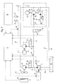
- FIG. 1 shows a first embodiment of the drive according to the invention for driving auxiliary units of a vehicle.
- a drive motor 1 is by means of a drive motor shaft 2 with a controllable hydraulic pump 3 connected.
- the displacement volume of the hydraulic pump 3 is by means of a Adjustment device 4 according to the specification by an electronic Control unit 6 adjustable.
- the hydraulic pump 3 is hydraulic Circuit 5, 6, 8, 9, 36, which has individual branch lines 6, 8 or 9, connected to the hydraulic motors 10, 11, 12 and 13.
- the speed of the Drive motor 1 is controlled by the electronic control unit 6 by means of the Speed sensor 41 detected.
- the pressure in the high pressure line 5 of the hydraulic circuit can be from the electronic control unit 6 is detected by means of a pressure sensor 14 and used as a control variable for the adjustment of the adjusting device 4 become.
- the first hydraulic motor 10 drives a fan wheel 15 of a fan 16.
- the Fan 16 serves to cool the cooler 17, the temperature of which by means of a Temperature sensor 18 is detected by the electronic control unit 6.
- a first switching valve 19 by the electronic control unit 6 via a Actuator 20 can be operated.
- the first switching valve 19 is between a first switching position in which the switching valve is fully open is, and a second switching position in which the switching valve 19 a has throttled flow, switchable. In the throttled position of the Switching valve 19 is ensured that the fan wheel 15 a predetermined minimum speed, which is sufficient, a certain minimum cooling to ensure the cooler 17. If the entire control system fails or the temperature sensor 18, the switching valve 19 is opened to to drive the fan wheel 15 at increased speed.
- a second hydraulic motor 11 is used to drive a compressed air compressor 21, which via a compressed air line 22 with compressed air storage containers 23 in Connection is established.
- the air pressure in the compressed air line 22 is from the electronic control unit 6 detected by means of a compressed air sensor 24. If the compressed air line falls below a specified compressed air threshold 22 becomes the switching valve 25 by actuating the actuating element 26 closed until the pressure in the compressed air line 22 an upper Compressed air threshold has exceeded.
- the adjustable in terms of its displacement volume hydraulic motor 13 and with this coupled auxiliary hydraulic motor 12 with a constant displacement are not used to drive an air conditioning compressor 27 air conditioning.
- the air conditioning compressor 27 is on a constant speed shaft 28 arranged.
- a flow rate sensor 30 is provided for adjusting the speed of the constant speed shaft 28 to a predetermined target value is in the delivery line 29 of the Auxiliary hydraulic motor 12, a flow rate sensor 30 is provided.
- the flow rate sensor 30 detects the flow rate, i.e. the flow volume per unit of time, in the delivery line 29.
- By using an auxiliary hydraulic motor with The constant displacement is the flow rate in the flow line 29 proportional to the speed of the constant speed shaft 28.
- the exemplary embodiment is the flow rate sensor 30 as a throttle-like constriction formed in the form of an orifice plate.
- the pressure difference ⁇ p is over two hydraulic measuring lines 31 and 32 of an adjusting device for the controllable hydraulic motor 13 supplied.
- the displacement volume of the controllable hydraulic motor 13 decreases when the flow rate sensor detected flow rate and thus the speed of the constant speed shaft 28th is greater than a predetermined threshold.
- By swiveling the controllable hydraulic motor 13 to a lower displacement volume will of this exerted on the constant speed shaft 28 reduced torque. This reduces the speed of the constant speed shaft 28 until the predetermined setpoint is reached again.
- controllable Hydraulic motor 13 further pivoted to a larger displacement, if the flow detected by the flow sensor 30 and thus the Speed of the constant speed shaft 28 is less than a predetermined setpoint is. Accordingly, the variable from the hydraulic motor 13 Constant speed shaft 28 exerted torque increased until the predetermined Setpoint is reached again.
- the drive device for the constant speed shaft 28 is also a Switch valve 34 assigned by the electronic control unit 6th can be switched by means of the actuating element 35.
- That of the Air conditioning compressor 27 operated air conditioning can be switched on and off.
- the hydraulic circuit is through a return line 36 and leakage fluid lines 37 and 38 closed, which lead to a pressure medium tank 39.
- the embodiment shown in Figure 1 is used in particular for Use in buses and other passenger transportation vehicles.
- the electronic Control unit 6 is the central electronics unit 40 of the Vehicle activated.
- the individual auxiliary units 16, 21, 27 can a priority-based assignment. For example, can - if that of the Hydropump 3 provided power not for simultaneous Operation of all units is sufficient - the air conditioning compressor 27 is switched off be when the compressed air compressor 21 is switched on. The compressed air compressor comes because of the priority actuation of the pneumatic operated entrance doors and the braking system a higher priority than that Air conditioning too.
- FIG. 2 shows a second embodiment of the drive according to the invention for the auxiliary units of a vehicle.
- This drive is especially for Suitable for use in commercial vehicles.
- the already on the basis of FIG described components are provided with the same reference numerals, so that a repetitive description is unnecessary.
- the embodiment of Figure 2 differs from that of Figure 1 in that the constant speed shaft 28 is a transfer case 50th is connected downstream, so that several auxiliary units 21, 27, 51 and 52 of the Constant speed shaft 28 can be driven.
- This embodiment is the air conditioning compressor 27, the Air compressor 21, an oil pump 51 and an electric generator 52.
- Individual auxiliary units can be operated by means of couplings 53 and 54 which can be triggered remotely be releasably coupled to the transfer case 50.
- the transfer case 50 can simultaneously increase and decrease the speed the constant speed shaft 28 to that for the corresponding auxiliary unit intended drive speed.
- a pressure medium cooler 55 and a filter 56 are also shown in FIG shown, which of course also in the embodiment of Figure 1 are useful.
- Figures 3 and 4 show specific configurations of the speed control of the Constant speed shaft 28. As already described, are on the branch line 9 of the hydraulic circuit of the hydraulic motor 13 with adjustable displacement and the auxiliary hydraulic motor 12 with constant displacement arranged in parallel. Both hydraulic motors 12 and 13 are on the constant speed shaft 28 coupled.
- the flow rate sensor 30 is in the exemplary embodiments 3 and 4 designed as a throttle-like constriction.
- the pressure difference p serves between the hydraulic measuring lines 31 and 32 for controlling a switching valve 60 against the spring force of a return spring 61.
- the piston 62 an actuator 63 with a working pressure from the branch line 9 of hydraulic circuit applied to the controllable hydraulic motor 13 to swing back a lower displacement volume and thus that of the controllable hydraulic motor 13 exerted on the constant speed shaft 28 Reduce torque.
- FIG. 4 shows a further embodiment of the control device Regulation of the speed of the constant speed shaft 28.
- the delivery line 29 of the auxiliary hydraulic motor 12 is a throttle-like as flow rate sensor 30 Narrowing provided, the cross section of which can be made variable.
- the pressure difference ⁇ p between the hydraulic measuring lines 31 and 32 serves to control a control valve 70, which the working pressure line 71st with a working pressure that corresponds to the pressure difference between the Measuring lines 31 and 32 is proportional.
- the control valve 70 is included the branch line 9 and the line 37 leading to the pressure medium tank 39 connected.
- the working pressure in the working pressure line 71 acts on the Piston 72 of the actuator 73 and the piston rod 74 adjusts the Setting the displacement volume of the controllable hydraulic motor 13. Thereby counteracts the return pressure of the return spring 76.
- an increase in the speed of the constant speed shaft causes 28 an increase in the flow rate through the constant auxiliary hydraulic motor 12 and thus an increase in the pressure difference between the hydraulic Measuring lines 31 and 32.
- the predetermined target speed of the constant speed shaft 28 is thus settled again.
- it has an effect on the target speed reduced speed of the constant speed shaft 28 a reduced Flow through the auxiliary hydraulic motor 12 and thus a reduced Pressure difference between the measuring lines 31 and 32.
- the setpoint of the speed of the constant speed shaft 28 can be both by adjusting the return spring 75 of the control valve 70 and the Specify the cross section of the restriction of the flow rate sensor 30.
- the Constant speed shaft 28 serves primarily to drive the air conditioning compressor for the air conditioning. However, it is also for driving other Auxiliary units are an advantage.
- the invention is not based on the exemplary embodiments described above limited.
- the one described with reference to FIGS. 3 and 4 hydraulic design of the control circuit also by appropriate electronic or pneumatic components can be replaced.
- the electromagnetic influence of the electronic control unit 6 on the adjusting device 4 and the actuating elements 20, 26 and 35 hydraulic or pneumatic action may also be provided.
- auxiliary hydraulic motor 12 and the delivery flow sensor 30 instead of the auxiliary hydraulic motor 12 and the delivery flow sensor 30 also any other suitable device for detecting the speed shaft 28 and to readjust the same use.
Landscapes
- Engineering & Computer Science (AREA)
- Mechanical Engineering (AREA)
- Chemical & Material Sciences (AREA)
- Combustion & Propulsion (AREA)
- Transportation (AREA)
- Fluid-Pressure Circuits (AREA)
- Auxiliary Drives, Propulsion Controls, And Safety Devices (AREA)
Description
- Fig. 1
- einen Schaltplan eines hydrostatischen Antriebs gemäß einem ersten Ausführungsbeispiel der Erfindung;
- Fig. 2
- einen Schaltplan eines hydrostatischen Antriebs gemäß einem zweiten Ausführungsbeispiel der Erfindung;
- Fig. 3
- eine detailliertere Darstellung der Regelvorrichtung zum Regeln der Konstantdrehzahlwelle gemäß einem ersten Ausführungsbeispiel;
- Fig. 4
- eine detailliertere Darstellung der Regelvorrichtung zum Regeln der Konstantdrehzahlwelle gemäß einem zweiten Ausführungsbeispiel.
Claims (12)
- Hydrostatischer Antrieb eines Lüfters (16) und weiterer Nebenaggregate (21, 27, 51, 52) eines Fahrzeugs mit
einem Antriebsmotor (1) und
einem hydraulischen Kreislauf (5, 6, 8, 9, 36), in welchem eine an den Antriebsmotor (1) gekoppelte Hydropumpe (3),
ein erster Hydromotor (10) zum Antrieb des Lüfters (16) und
weitere Hydromotoren (11-13) zum Antrieb der weiteren Nebenaggregate (21, 27, 51, 52) angeordnet sind,
wobei das Fördervolumen der Hydropumpe (3) regelbar ist, und wobei
daß zum Antrieb zumindest eines der weiteren Nebenaggregate (27) eine Konstantdrehzahlwelle (28) vorgesehen ist, die von einem regelbaren Hydromotor (13) angetrieben wird, dessen Verdrängungsvolumen von einer Regelvorrichtung (31-33) so geregelt wird, daß die Konstantdrehzahlwelle (28) mit im wesentlichen konstanter Drehzahl rotiert,
dadurch gekennzeichnet, daß in dem hydraulischen Kreislauf (5, 6, 8, 9, 36) eine Verteilereinrichtung (19, 25, 34) zum Verteilen des von der Hydropumpe (3) geförderten Volumenstroms auf die einzelnen Hydromotoren (10-13) vorgesehen ist, die den ersten Hydromotor (10) zumindest mit einem Mindest-Volumenstrom versorgt, so daß eine vorgegebene Mindestdrehzahl des Lüfters (16) nicht unterschritten wird. - Hydrostatischer Antrieb nach Anspruch 1,
dadurch gekennzeichnet, daß mit der Konstantdrehzahlwelle (28) ein Hilfs-Hydromotor (12) gekoppelt ist, der mit dem hydraulischen Kreislauf (5, 6, 8, 9, 36) über eine Förderleitung (29) verbunden ist, deren Förderstrom von einem Förderstrom-Sensor (30) erfaßt wird und
daß die Regelvorrichtung (31-33) das Verdrängungsvolumen des die Konstantdrehzahlwelle (28) antreibenden, regelbaren Hydromotors (13) bei Zunahme des von dem Förderstrom-Sensor (30) erfaßten Förderstroms reduziert und mit Abnahme des erfaßten Förderstroms vergrößert. - Hydrostatischer Antrieb nach Anspruch 2,
dadurch gekennzeichnet, daß der Förderstrom-Sensor (30) durch eine drosselartige Verengung gebildet ist, an der sich eine dem Förderstrom proportionale Druckdifferenz einstellt. - Hydrostatischer Antrieb nach Anspruch 2 oder 3,
dadurch gekennzeichnet, daß die Regelvorrichtung (31, 32, 60-62) ein Schaltventil (60) umfaßt, das ein das Verdrängungsvolumen des regelbaren Hydromotors (13) verstellenden Stellgliedes (63) mit der Hochdruckleitung (9) des hydraulischen Kreislaufs (5, 6, 8, 9, 36) verbindet, um das Verdrängungsvolumen des regelbaren Hydromotors (13) zu reduzieren, wenn der von dem Förderstrom-Sensor (30) erfaßte Förderstrom einen vorgegebenen Förderstrom überschreitet. - Hydrostatischer Antrieb nach Anspruch 2 oder 3,
dadurch gekennzeichnet, daß die Regelvorrichtung (31, 32, 70-76) ein mit der Hochdruckleitung (9) des hydraulischen Kreislaufs (5, 6, 8, 9, 36) und einem Druckmitteltank (39) verbundenes Steuerventil (70) umfaßt, das ein das Verdrängungsvolumen des regelbaren Hydromotors (13) verstellendes Stellglied (73) mit einem Arbeitsdruck beaufschlagt, der von dem durch den Förderstrom-Sensor (30) erfaßten Förderstrom abhängt. - Hydrostatischer Antrieb nach Anspruch 5 und 3,
dadurch gekennzeichnet, daß das Stellglied (73) mit einem der Druckdifferenz an dem Förderstrom-Sensor (30) proportionalen Arbeitsdruck beaufschlagt wird. - Hydrostatischer Antrieb nach einem der Ansprüche 1 bis 6,
dadurch gekennzeichnet, daß die Verteilereinrichtung mehrere Schaltventile (19, 25, 34) umfaßt, die in die Hydromotoren (10-13) versorgenden Zweigleitungen (6, 8, 9) des hydraulischen Kreislaufs (5, 6, 8, 9, 36) angeordnet sind. - Hydrostatischer Antrieb nach Anspruch 7,
dadurch gekennzeichnet, daß das Schaltventil (19) in der Zweigleitung (6), die den ersten Hydromotor (10) versorgt, zwischen einer ersten Schaltstellung, in der das Schaltventil (19) voll geschlossen ist, und einer zweiten Schaltstellung, in der das Schaltventil einen geöffneten Durchfluß aufweist, schaltbar ist. - Hydrostatischer Antrieb nach einem der Ansprüche 1 bis 8,
dadurch gekennzeichnet, daß der Konstantdrehzahlwelle (28) ein Verteilergetriebe (50) nachgeschaltet ist, um mehrere Nebenaggregate parallel anzutreiben. - Hydrostatischer Antrieb nach Anspruch 9,
dadurch gekennzeichnet, daß einzelne Nebenaggregate (21, 27) über fernauslösbare Kupplungen (53, 54) mit dem Verteilergetriebe (50) lösbar koppelbar sind. - Hydrostatischer Antrieb nach einem der Ansprüche 1 bis 10,
dadurch gekennzeichnet, daß es sich bei den weiteren Nebenaggregaten (21, 27, 51, 52) um einen Klima-Kompressor (27) für die Klimaanlage und/oder einen Druckluft-Kompressor (21) und/oder eine Ölpumpe (51) und/oder einen elektrischen Generator (52) handelt. - Hydrostatischer Antrieb nach Anspruch 11,
dadurch gekennzeichnet, daß zumindest der Klima-Kompressor (27) von der Konstantdrehzahlwelle (28) angetrieben ist.
Applications Claiming Priority (2)
| Application Number | Priority Date | Filing Date | Title |
|---|---|---|---|
| DE19530837 | 1995-08-22 | ||
| DE19530837A DE19530837A1 (de) | 1995-08-22 | 1995-08-22 | Hydrostatischer Antrieb für Nebenaggregate eines Fahrzeugs |
Publications (3)
| Publication Number | Publication Date |
|---|---|
| EP0759371A2 EP0759371A2 (de) | 1997-02-26 |
| EP0759371A3 EP0759371A3 (de) | 1998-05-13 |
| EP0759371B1 true EP0759371B1 (de) | 2002-07-17 |
Family
ID=7770084
Family Applications (1)
| Application Number | Title | Priority Date | Filing Date |
|---|---|---|---|
| EP96112572A Expired - Lifetime EP0759371B1 (de) | 1995-08-22 | 1996-08-02 | Hydrostatischer Antrieb für Nebenaggregate eines Fahrzeugs |
Country Status (2)
| Country | Link |
|---|---|
| EP (1) | EP0759371B1 (de) |
| DE (2) | DE19530837A1 (de) |
Families Citing this family (3)
| Publication number | Priority date | Publication date | Assignee | Title |
|---|---|---|---|---|
| DE19717708C2 (de) * | 1997-04-18 | 1999-11-18 | Mannesmann Ag | Hydraulischer Antrieb für ein fahrbares Arbeitsgerät |
| DE10004051A1 (de) * | 2000-01-31 | 2001-08-09 | Voith Turbo Kg | Verfahren zur Leistungsbereitstellung für Nebenverbraucher in elektrischen Antriebssystemen und elektrisches Antriebssystem |
| DE10139190C1 (de) * | 2001-08-16 | 2002-08-22 | Webasto Thermosysteme Gmbh | Fahrzeugklimasystem mit mehreren Fluidkreisläufen |
Family Cites Families (9)
| Publication number | Priority date | Publication date | Assignee | Title |
|---|---|---|---|---|
| DE2208842C2 (de) * | 1972-02-25 | 1983-09-01 | Robert Bosch Gmbh, 7000 Stuttgart | Antrieb einer Lenkeinrichtung und mehrerer Zubehörgeräte für Fahrzeuge durch ein hydrostatisches Getriebe |
| DE3236580A1 (de) * | 1982-10-02 | 1984-04-05 | Robert Bosch Gmbh, 7000 Stuttgart | Steuereinrichtung fuer einen hydrostatischen antrieb |
| DE3628444A1 (de) * | 1986-02-08 | 1987-08-13 | Bosch Gmbh Robert | Hydrostatischer antrieb von nebenaggregaten eines fahrzeugs |
| DE3902138A1 (de) * | 1989-01-25 | 1990-07-26 | Bosch Gmbh Robert | Hydrostatischer antrieb von nebenaggregaten eines kraftfahrzeugs |
| DE3911531A1 (de) * | 1989-04-08 | 1990-07-26 | Daimler Benz Ag | Hydraulik-system fuer kraftfahrzeuge |
| DE4212984C2 (de) * | 1992-02-07 | 1995-07-06 | Man Nutzfahrzeuge Ag | Kraftfahrzeug mit mittels Abgasturbolader aufladbarer Brennkraftmaschine und hydrostatisch-mechanischem Antrieb der Nebenaggregate |
| DE4238998A1 (de) * | 1992-11-19 | 1994-05-26 | Bosch Gmbh Robert | Hydrostatischer Antrieb von Nebenaggregaten in einem Kraftfahrzeug |
| DE4337210A1 (de) * | 1993-10-30 | 1995-05-04 | Rexroth Mannesmann Gmbh | Zentralhydraulikanlage für ein Kraftfahrzeug |
| DE4342006A1 (de) * | 1993-12-09 | 1995-06-14 | Bosch Gmbh Robert | Hydraulisches Bordnetz für Fahrzeuge |
-
1995
- 1995-08-22 DE DE19530837A patent/DE19530837A1/de not_active Withdrawn
-
1996
- 1996-08-02 DE DE59609442T patent/DE59609442D1/de not_active Expired - Fee Related
- 1996-08-02 EP EP96112572A patent/EP0759371B1/de not_active Expired - Lifetime
Also Published As
| Publication number | Publication date |
|---|---|
| EP0759371A3 (de) | 1998-05-13 |
| DE59609442D1 (de) | 2002-08-22 |
| EP0759371A2 (de) | 1997-02-26 |
| DE19530837A1 (de) | 1997-02-27 |
Similar Documents
| Publication | Publication Date | Title |
|---|---|---|
| DE3716200C2 (de) | Steuer- und Regeleinrichtung für ein hydrostatisches Antriebsaggregat und Verfahren zum Betreiben eines solchen | |
| EP0873475B1 (de) | Verlustarmer antrieb für mehrere hydraulische aktuatoren | |
| DE4320145C2 (de) | Klimaanlage für Kraftfahrzeuge | |
| DE60315307T2 (de) | Pumpeneinheit | |
| DE3925090A1 (de) | Verfahren zum betrieb einer kaelteanlage | |
| DE19538649A1 (de) | Leistungsregelung mit Load-Sensing | |
| DE10000110B4 (de) | Hydrostatischer Fahrzeugantrieb mit Steuerungseinrichtung und Steuerungseinrichtung für hydrostatische Antriebe | |
| DE19906230B4 (de) | Einrichtung und Verfahren zur Kopplung einer Vielzahl von Pumpen | |
| DE4136396C2 (de) | Hydrauliksystem für ein Fahrzeug | |
| DE19513032C1 (de) | Vorrichtung zum Verstellen des Fördervolumens einer Hydropumpe | |
| EP1288507A2 (de) | Verlustarmer Antrieb für einen hydraulischen Aktuator | |
| EP0976635B2 (de) | Druckluftversorgungseinrichtung für Fahrzeug-Druckluftanlagen und Verfahren zum Energiesparen bei Druckluftaufbereitungsanlagen | |
| DE19531413B4 (de) | Anordnung zur Versorgung der hydraulischen Lenkung eines Kraftfahrzeugs | |
| DE3834201A1 (de) | Anordnung zum zufuehren von druckmittel zu hydraulischen verbrauchern | |
| EP0190431B1 (de) | Hydraulikanlage | |
| DE4313597B4 (de) | Verfahren zum Betreiben einer verstellbaren hydrostatischen Pumpe und dafür ausgebildetes hydrostatisches Antriebssystem | |
| DE4304403C2 (de) | Regeleinrichtung für einen hydrostatischen Antrieb | |
| EP1017942B1 (de) | Regeleinrichtung für eine verstellbare hydropumpe mit mehreren verbrauchern | |
| DE19654781A1 (de) | Hilfseinrichtung zur Realisierung einer Redundanz für die Energieversorgung von Flugsteuerungsantrieben | |
| EP0759371A2 (de) | Hydrostatischer Antrieb für Nebenaggregate eines Fahrzeugs | |
| DE4238998A1 (de) | Hydrostatischer Antrieb von Nebenaggregaten in einem Kraftfahrzeug | |
| DE19753915A1 (de) | Einrichtung zur Druckmittelversorgung von hydraulischen Verbrauchern | |
| DE102009054217B4 (de) | Hydraulikanordnung | |
| DE3917243A1 (de) | Einrichtung zur druckoelversorgung von lastschaltgetrieben | |
| DE102006039698B3 (de) | Förderpumpe |
Legal Events
| Date | Code | Title | Description |
|---|---|---|---|
| PUAI | Public reference made under article 153(3) epc to a published international application that has entered the european phase |
Free format text: ORIGINAL CODE: 0009012 |
|
| AK | Designated contracting states |
Kind code of ref document: A2 Designated state(s): DE FR GB IT SE |
|
| PUAL | Search report despatched |
Free format text: ORIGINAL CODE: 0009013 |
|
| AK | Designated contracting states |
Kind code of ref document: A3 Designated state(s): DE FR GB IT SE |
|
| 17P | Request for examination filed |
Effective date: 19980610 |
|
| GRAG | Despatch of communication of intention to grant |
Free format text: ORIGINAL CODE: EPIDOS AGRA |
|
| GRAG | Despatch of communication of intention to grant |
Free format text: ORIGINAL CODE: EPIDOS AGRA |
|
| GRAH | Despatch of communication of intention to grant a patent |
Free format text: ORIGINAL CODE: EPIDOS IGRA |
|
| 17Q | First examination report despatched |
Effective date: 20011218 |
|
| GRAH | Despatch of communication of intention to grant a patent |
Free format text: ORIGINAL CODE: EPIDOS IGRA |
|
| GRAA | (expected) grant |
Free format text: ORIGINAL CODE: 0009210 |
|
| AK | Designated contracting states |
Kind code of ref document: B1 Designated state(s): DE FR GB IT SE |
|
| REG | Reference to a national code |
Ref country code: GB Ref legal event code: FG4D Free format text: NOT ENGLISH |
|
| GBT | Gb: translation of ep patent filed (gb section 77(6)(a)/1977) |
Effective date: 20020717 |
|
| REF | Corresponds to: |
Ref document number: 59609442 Country of ref document: DE Date of ref document: 20020822 |
|
| ET | Fr: translation filed | ||
| PLBE | No opposition filed within time limit |
Free format text: ORIGINAL CODE: 0009261 |
|
| STAA | Information on the status of an ep patent application or granted ep patent |
Free format text: STATUS: NO OPPOSITION FILED WITHIN TIME LIMIT |
|
| 26N | No opposition filed |
Effective date: 20030422 |
|
| PGFP | Annual fee paid to national office [announced via postgrant information from national office to epo] |
Ref country code: DE Payment date: 20070822 Year of fee payment: 12 |
|
| PGFP | Annual fee paid to national office [announced via postgrant information from national office to epo] |
Ref country code: GB Payment date: 20070823 Year of fee payment: 12 |
|
| PGFP | Annual fee paid to national office [announced via postgrant information from national office to epo] |
Ref country code: SE Payment date: 20070815 Year of fee payment: 12 Ref country code: IT Payment date: 20070827 Year of fee payment: 12 |
|
| PGFP | Annual fee paid to national office [announced via postgrant information from national office to epo] |
Ref country code: FR Payment date: 20070812 Year of fee payment: 12 |
|
| EUG | Se: european patent has lapsed | ||
| GBPC | Gb: european patent ceased through non-payment of renewal fee |
Effective date: 20080802 |
|
| REG | Reference to a national code |
Ref country code: FR Ref legal event code: ST Effective date: 20090430 |
|
| PG25 | Lapsed in a contracting state [announced via postgrant information from national office to epo] |
Ref country code: IT Free format text: LAPSE BECAUSE OF NON-PAYMENT OF DUE FEES Effective date: 20080802 Ref country code: FR Free format text: LAPSE BECAUSE OF NON-PAYMENT OF DUE FEES Effective date: 20080901 Ref country code: DE Free format text: LAPSE BECAUSE OF NON-PAYMENT OF DUE FEES Effective date: 20090303 |
|
| PG25 | Lapsed in a contracting state [announced via postgrant information from national office to epo] |
Ref country code: GB Free format text: LAPSE BECAUSE OF NON-PAYMENT OF DUE FEES Effective date: 20080802 |
|
| PG25 | Lapsed in a contracting state [announced via postgrant information from national office to epo] |
Ref country code: SE Free format text: LAPSE BECAUSE OF NON-PAYMENT OF DUE FEES Effective date: 20080803 |