EP0755571B1 - Verfahren und vorrichtung zur chemischen behandlung von substraten - Google Patents
Verfahren und vorrichtung zur chemischen behandlung von substraten Download PDFInfo
- Publication number
- EP0755571B1 EP0755571B1 EP94917638A EP94917638A EP0755571B1 EP 0755571 B1 EP0755571 B1 EP 0755571B1 EP 94917638 A EP94917638 A EP 94917638A EP 94917638 A EP94917638 A EP 94917638A EP 0755571 B1 EP0755571 B1 EP 0755571B1
- Authority
- EP
- European Patent Office
- Prior art keywords
- reservoir
- fluid
- substrate
- hood
- chemical treatment
- Prior art date
- Legal status (The legal status is an assumption and is not a legal conclusion. Google has not performed a legal analysis and makes no representation as to the accuracy of the status listed.)
- Expired - Lifetime
Links
Images


Classifications
-
- H—ELECTRICITY
- H10—SEMICONDUCTOR DEVICES; ELECTRIC SOLID-STATE DEVICES NOT OTHERWISE PROVIDED FOR
- H10P—GENERIC PROCESSES OR APPARATUS FOR THE MANUFACTURE OR TREATMENT OF DEVICES COVERED BY CLASS H10
- H10P50/00—Etching of wafers, substrates or parts of devices
- H10P50/60—Wet etching
- H10P50/61—Electrolytic etching
- H10P50/613—Electrolytic etching of Group IV materials
-
- H—ELECTRICITY
- H10—SEMICONDUCTOR DEVICES; ELECTRIC SOLID-STATE DEVICES NOT OTHERWISE PROVIDED FOR
- H10P—GENERIC PROCESSES OR APPARATUS FOR THE MANUFACTURE OR TREATMENT OF DEVICES COVERED BY CLASS H10
- H10P72/00—Handling or holding of wafers, substrates or devices during manufacture or treatment thereof
- H10P72/04—Apparatus for manufacture or treatment
- H10P72/0402—Apparatus for fluid treatment
- H10P72/0418—Apparatus for fluid treatment for etching
- H10P72/0422—Apparatus for fluid treatment for etching for wet etching
-
- B—PERFORMING OPERATIONS; TRANSPORTING
- B01—PHYSICAL OR CHEMICAL PROCESSES OR APPARATUS IN GENERAL
- B01J—CHEMICAL OR PHYSICAL PROCESSES, e.g. CATALYSIS OR COLLOID CHEMISTRY; THEIR RELEVANT APPARATUS
- B01J19/00—Chemical, physical or physico-chemical processes in general; Their relevant apparatus
- B01J19/08—Processes employing the direct application of electric or wave energy, or particle radiation; Apparatus therefor
- B01J19/10—Processes employing the direct application of electric or wave energy, or particle radiation; Apparatus therefor employing sonic or ultrasonic vibrations
-
- C—CHEMISTRY; METALLURGY
- C23—COATING METALLIC MATERIAL; COATING MATERIAL WITH METALLIC MATERIAL; CHEMICAL SURFACE TREATMENT; DIFFUSION TREATMENT OF METALLIC MATERIAL; COATING BY VACUUM EVAPORATION, BY SPUTTERING, BY ION IMPLANTATION OR BY CHEMICAL VAPOUR DEPOSITION, IN GENERAL; INHIBITING CORROSION OF METALLIC MATERIAL OR INCRUSTATION IN GENERAL
- C23G—CLEANING OR DE-GREASING OF METALLIC MATERIAL BY CHEMICAL METHODS OTHER THAN ELECTROLYSIS
- C23G3/00—Apparatus for cleaning or pickling metallic material
-
- F—MECHANICAL ENGINEERING; LIGHTING; HEATING; WEAPONS; BLASTING
- F26—DRYING
- F26B—DRYING SOLID MATERIALS OR OBJECTS BY REMOVING LIQUID THEREFROM
- F26B21/00—Arrangements for supplying or controlling air or other gases for drying solid materials or objects
- F26B21/40—Arrangements for supplying or controlling air or other gases for drying solid materials or objects using gases other than air
-
- H—ELECTRICITY
- H10—SEMICONDUCTOR DEVICES; ELECTRIC SOLID-STATE DEVICES NOT OTHERWISE PROVIDED FOR
- H10P—GENERIC PROCESSES OR APPARATUS FOR THE MANUFACTURE OR TREATMENT OF DEVICES COVERED BY CLASS H10
- H10P72/00—Handling or holding of wafers, substrates or devices during manufacture or treatment thereof
- H10P72/04—Apparatus for manufacture or treatment
- H10P72/0402—Apparatus for fluid treatment
- H10P72/0406—Apparatus for fluid treatment for cleaning followed by drying, rinsing, stripping, blasting or the like
-
- H—ELECTRICITY
- H05—ELECTRIC TECHNIQUES NOT OTHERWISE PROVIDED FOR
- H05K—PRINTED CIRCUITS; CASINGS OR CONSTRUCTIONAL DETAILS OF ELECTRIC APPARATUS; MANUFACTURE OF ASSEMBLAGES OF ELECTRICAL COMPONENTS
- H05K3/00—Apparatus or processes for manufacturing printed circuits
- H05K3/0085—Apparatus for treatments of printed circuits with liquids not provided for in groups H05K3/02 - H05K3/46; conveyors and holding means therefor
-
- Y—GENERAL TAGGING OF NEW TECHNOLOGICAL DEVELOPMENTS; GENERAL TAGGING OF CROSS-SECTIONAL TECHNOLOGIES SPANNING OVER SEVERAL SECTIONS OF THE IPC; TECHNICAL SUBJECTS COVERED BY FORMER USPC CROSS-REFERENCE ART COLLECTIONS [XRACs] AND DIGESTS
- Y10—TECHNICAL SUBJECTS COVERED BY FORMER USPC
- Y10S—TECHNICAL SUBJECTS COVERED BY FORMER USPC CROSS-REFERENCE ART COLLECTIONS [XRACs] AND DIGESTS
- Y10S134/00—Cleaning and liquid contact with solids
- Y10S134/902—Semiconductor wafer
Definitions
- the invention relates to a method for chemical treatment of substrates in which at least one substrate after a chemical treatment, a rinsing process and is subjected to a drying process Chemical treatment device as described above.
- an automatic wet bench has a number of Basins or tanks for a sequence of chemical wet processes on. After completing a certain chemical process sequence a substrate, for example a silicon wafer, into a separate sink or rinsing basin, submerged and then dried.
- a substrate for example a silicon wafer
- the drying of a substrate can, for example, by means of a centrifuge, but also during the slow Removing the substrate from the sink.
- the devices and methods described have following disadvantages:
- the sink is in any case a pool separated from the rest of the process pool and only serves to rinse the substrates.
- On own sink means an increased space or space requirements.
- the substrate must also be cleaned before the rinsing step through the surface of a fluid for chemical Treatment in the air and then back in the Flushing fluid, which is known to have adverse consequences for May have particle contamination of the substrate. This particularly meets hydrophobic surfaces (for example after HF treatment).
- the insertion or Removing substrates in or from different Basin for chemical treatment or rinsing step mean an increased expenditure of time. Is also at the known devices or methods always one Cassette (carrier) required for handling the substrates.
- From US-A-5 275 184 is a treatment device known from wafers, in which the wafers both during the Fluid treatment process as well during the Drying process in a treatment chamber with negative pressure lie in a wafer lifting mechanism. Therefore apply those previously described in connection with US-A-4,722,752 Disadvantages here too, since the wafers during the Drying process in the wafer lifting mechanism and the drying is therefore not optimal. The The drying process is also slower because additional the lifting device dried to the wafers will or must be. A cassette-free treatment of the Substrates during the drying process are therefore not possible.
- WO-A-9 212 533 describes a drying device known from substrates in which the substrates both during of the rinsing or treatment process as well of the drying process are arranged in a cassette.
- this device has the same disadvantages as the aforementioned known devices.
- the container is used both during cleaning and during the drying process closed with a lid held. Via an inlet pipe in the upper area inert gas is introduced into the container after extraction, which takes the place of the cleaning liquid occurs, which is drained after the cleaning process.
- the invention is therefore based on the object of a method for wet chemical treatment or a device to specify or create for this procedure, the Process flow rationalized in an automatic wet bench, d. H. Saves time and space.
- Another The object of the invention is the contamination of the substrates during such a sequence of chemical To keep wet processes as low as possible.
- Finally is another object of the invention is the ability on a cassette or similar for holding the substrates or in connection with the insertion or extension of the To waive substrates in or out of the pool.
- the chemical treatment and the Rinsing process in the same basin realized that a fluid for chemical treatment by another such fluid is supplemented or (partially) replaced and / or is replaced by a flushing fluid.
- a fluid for chemical treatment by another such fluid is supplemented or (partially) replaced and / or is replaced by a flushing fluid.
- a flushing fluid Preferably is presented in a sequential chemical process replacing the chemical treatment fluid with another such fluid is first introduced a rinsing fluid and the substrate or substrates from the tank removed and dried at the same time. Subsequently the rinsing fluid is chemical by another fluid Treatment replaced and the substrate back into the Pool retracted.
- the drying process takes place during removing the substrate from the rinse fluid. This includes usually a very slow exit of the substrate from the rinsing fluid.
- a vapor is applied to the substrate that is not condensed on the substrate and settled with the rinse fluid mixes.
- the mixture has a lower one Surface tension than the rinse fluid, which means that there is a force that sticks to the substrate Flushing fluid pushed back into the basin.
- Replacing the chemical treatment fluid with the flushing fluid is done in a preferred embodiment by ousting. Deriving e.g. of the fluid for chemical treatment and subsequent supply of the rinse fluid would have a substrate exposure increased particle contamination in the air.
- the Displacing one fluid by the other, e.g. the Flushing fluid has the advantage that the substrate has no phase boundary must penetrate and not exposed to the air becomes.
- several fluids can also be used chemical treatment before rinsing by displacement replace each other.
- the replacement can also be a partial replacement, i.e. including mixing.
- the flushing fluid is preferably introduced into the basin and at the same time the mixture of fluid for chemical Treatment and the fluid derived.
- the introduction of the flushing fluid and the discharge of the fluid for chemical treatment is preferably carried out on various Places the pelvis. This will, for example the replacement of one fluid with the other optimized in time.
- the flushing fluid is preferably introduced from the bottom of the basin while draining the mixture by overflowing. So for deriving is no additional pumping device required.
- Discharge from the bottom of the pool i.e. far from the place of the Deriving, as little as possible of the initiated Rinsing fluid derived. Also in terms of gravity can this, possibly with additional temperature gradients, be beneficial. This is economically advantageous and time-saving.
- HF dilute hydrofluoric acid
- a Treatment with ozone is carried out when intended on one, for example for cleaning reasons with HF treated (hydrophobic) substrate surface to grow a chemical oxide again and thus creating a hydrophilic surface.
- the input and / or Moving out of at least one substrate in or out a basin the substrate in the basin by a knife of a receiving device retracted and / or moved out.
- An advantage of the invention is that Cassette as a holder for the substrates or for insertion or Extending the substrates can be dispensed with.
- the invention therefore does not require a carrier.
- the recording device according to the invention is not a carrier but only a retractable and extendable support for one or more substrate (s).
- Carrierless drying not only saves the step of drying a carrier one, but reduces the rinsing process Flushing time but also the consumption of flushing fluid. Likewise is the carryover of chemicals into the dryer reduced by the carrierless process control.
- the receiving device advantageously consists of a two-part support device and one separately vertically movable knife.
- the knife moves the substrate so far out of the pool that it is from the guides, the one on the opposite inside Hood are attached, guided or held.
- the movable brackets below or in the hood are designed such that if the substrates are held by the movable brackets be opened or closed without further ado can be made without the location of the substrates change.
- the moving brackets are always dry and only with the already dried substrates Contact.
- the method according to the invention advantageously sees a support for the rinsing or cleaning step through ultrasound or megasound.
- piezo elements are provided on the basin to generate sound waves to clean the substrates.
- Such one "Megasonic" system is special in this context advantageous because the particle contamination of the substrates in the process according to the invention to a minimum is reduced. This makes an extremely thorough cleaning of the substrates achieved.
- an outer basin is provided on its outside, the serves as a safety reservoir, for example.
- a diffuser preferably at the bottom of the pool, is advantageously provided as the introduction device. This is useful, for example, for the ozone (O 3 ) mentioned above.
- a liquid such as diluted Hydrofluoric acid
- an induction mechanism also preferably at the bottom of the pool, advantageous.
- a hood is located above the basin in order to protect the basin or the dried substrate from particle contamination and to ensure a dense vapor atmosphere in the area above the basin.
- the hood has an integrated diffuser, ie a perforated diffuser plate integrated in the hood, for the supply or distribution of an IPA (isopropyl alcohol) / N 2 mixture.
- IPA isopropyl alcohol
- N 2 mixture for the supply or distribution of an IPA (isopropyl alcohol) / N 2 mixture.
- the IPA is mixed with the nitrogen in a gas wash bottle (bubbler).
- the substrate is in the basin by means of a Holding device held from a knife-shaped Part, the so-called, knife, and z. B.
- a Holding device held from a knife-shaped Part, the so-called, knife, and z.
- two Support devices exist.
- the knife and the support devices each movable relative to each other and the knife is advantageously between the two Support devices arranged.
- the requirements are in Basin provided while the knife is also out of the liquid can show up.
- the hood over the basin Guide for the substrate. This is preferred on the inside of the hood on two opposite Sides attached.
- a substrate such as. a silicon wafer.
- the guide is on opposite sides of the hood attached. It has a groove-shaped shape for receiving of multiple substrates. This allows for a cassette to hold the substrate.
- the guide in the hood is preferably in two parts executed, with at least one edge of the receptacle beveled to facilitate picking up the substrate.
- At least part of the leadership a bevelled edge, for easier mounting of the substrates. This also simplifies opening and Closing the hood.
- movable brackets provided below the Hood and above the basin over the basin from the outside can be retracted, and a circular section Have deepening.
- the movable brackets can just like the inclusion in the hood and also like the ensemble of knife and the two support devices hold the substrate alone in the pool. Does that rest? Substrate on the circular segment-shaped depressions of the movable brackets and it will from taking in the hood fixed, so the hood can be carried without carrying the Substrates are opened. The substrates are then left alone held by the movable brackets until the system dealer removed from it for further processing.
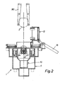
- the device 1 shows a device for chemical wet treatment 1 of substrates, in particular a wafer 2.
- the device 1 consists of an outer basin 5 and an inner basin 10.
- the outer basin 5 has an outer annular chamber 6 and an inner annular chamber 7 on.
- a hood 12 with an opening mechanism 13 for covering the inner basin 10 is arranged above the inner basin 10.
- the hood 12 has a space delimited by a diffuser plate 14, into which, for example, an IPA / N 2 mixture can be introduced.
- the inner basin 10 consists of a narrow cylinder 18 at the lower end of the inner basin 10.
- a frustoconical intermediate section 20 extends the diameter of the inner basin 10 to a wide cylinder 19. At the upper edge of the inner basin 10, the edge is designed as an inclined outer edge 23.
- the inner basin 10 has at its bottom 11 two inlet devices arranged one above the other, namely a diffuser 25 and an inlet mechanism 26.
- the diffuser 25 is arranged above the introduction mechanism 26.
- the diffuser 25 is connected via a feed line 30 to a fluid container 35 which preferably contains ozone (O 3 ). In the drawing, the direction of flow of the ozone is shown by an arrow.
- the introduction mechanism 26 is connected to a pump 36 via a feed line 31.
- the pump 36 optionally pumps a fluid for chemical treatment for the wafer 2, such as, for example, dilute hydrofluoric acid, from the fluid reservoir 37 or 38 via the lines 39 or 40.
- a fluid for chemical treatment for the wafer 2 such as, for example, dilute hydrofluoric acid
- an arrow represents the direction of flow of the pumped fluid in the feed line 31.
- right and left support devices 43 and 44 which are fixed in two brackets 46 and 47, which are parallel can be adjusted in height in the inner basin 10.
- the right and left support devices 43, 44 have a circular cutout 60 and 61 for receiving the wafer 2.
- knife 42 In the middle between the two support devices 43, 44 there is a so-called knife 42, ie an elongated element with a pointed edge.
- the knife 42 is made, for example, of quartz glass and can be moved in height independently of the right and left support devices 43 and 44.
- Fig. 1 it can be seen that the knife 42 has raised the wafer 2 from the inner basin 10 and the wafer 2 is held in the hood 12 by a holder 51 above the inner basin 10.
- the guide or wafer holder 51 has a groove shape in order to handle a large number of wafers at the same time without a cassette.
- An inner edge 52 of the guide 51 is chamfered for easier insertion of the wafer 2 into the guide 51.
- the wafer or wafers 2 are held or guided by the guide 51.
- the outer basin 5 is closed off by a cover 8, which has an opening 9.
- the outer basin 5 which serves as a safety reservoir, consists of a narrow cylinder 48, which is connected to a wide cylinder 49 via an intermediate section 50, which is designed as a disk with a central circular opening.
- the wide cylinder 49 forms the outside of the inner annular chamber 7 or the inside of the outer annular chamber 6 from which the overflowed fluid can be drained off or pumped out through the opening 9.
- FIG. 2 shows the first step of a process flow, which is shown in Figs. 2 to 9.
- a wafer package represented by the a wafer 2 from a system handler 90 of the device is fed.
- the hood 12 with the wafer holder 51 was connected via the automatic cylinder 15 open.
- the knife 42 and the right and left Support devices 43 and 44 are ready for the wafer 2 to record.
- the knife 42 is somewhat lowered opposite the support device 43, 44, so that the tip of the knife 42 on a circular line with the circular cutouts 60 or 61, on which later the wafer 2 rests.
- Fig. 3 is now the deposition of a wafer 2 in the inner Basin 10, which is filled with HF, for example, shown.
- Fig. 4 it can be seen that the hood 12 over the inner Basin 10 is closed and the wafer 2 in the interior Basin 10 is lowered into a lower position approximately to the intermediate section 20, the knife 42 and the right and left support devices 43 and 44 with drive down at the same speed.
- FIG. 5 shows the drying step of the wafer 2, d. H. lifting the wafer 2 from the inside Basin 10.
- the chemical fluid HF replaced by another fluid preferably last a flushing fluid is introduced.
- a vapor onto the wafer above the inner basin 10 applied that does not condense on the wafer 2 and wherein the mixture between rinsing fluid and steam is less Surface tension than the flushing fluid alone has.
- the hood 12 is still closed.
- Knife 42 preferably drives one constant speed upwards, the two support devices 43 and 44 but only at half speed, which is why they stay behind.
- Fig. 8 it can be seen that before opening the hood 12th movable brackets 70 and 71 in the space above the interior Basin 10 can be retracted to the wafer 2 during or after opening the hood 12, i.e. removing the holder 51, from below in its position hold.
- the holder of the wafer 2 can be by the movable brackets 70 and 71 are effected, d. H. the knife 42, the support devices 43, 44 and the Wafer receptacle 51 are not used to hold the Wafers 2 needed.
- the movable brackets 70, 71 have circular segment-shaped incisions around the wafer 2 hold in place. Also in Fig. 8 recognizable that the knife 42 again in the inner pelvis 10 immersed, namely in its starting position (compare Fig. 2) below the right and left support devices 43 and 44.
Landscapes
- Chemical & Material Sciences (AREA)
- Engineering & Computer Science (AREA)
- Mechanical Engineering (AREA)
- Chemical Kinetics & Catalysis (AREA)
- Organic Chemistry (AREA)
- General Health & Medical Sciences (AREA)
- Toxicology (AREA)
- Health & Medical Sciences (AREA)
- General Engineering & Computer Science (AREA)
- General Chemical & Material Sciences (AREA)
- Materials Engineering (AREA)
- Metallurgy (AREA)
- Cleaning Or Drying Semiconductors (AREA)
- Container, Conveyance, Adherence, Positioning, Of Wafer (AREA)
- Cleaning In General (AREA)
- Exposure Of Semiconductors, Excluding Electron Or Ion Beam Exposure (AREA)
Applications Claiming Priority (3)
| Application Number | Priority Date | Filing Date | Title |
|---|---|---|---|
| DE4413077 | 1994-04-15 | ||
| DE4413077A DE4413077C2 (de) | 1994-04-15 | 1994-04-15 | Verfahren und Vorrichtung zur chemischen Behandlung von Substraten |
| PCT/EP1994/001585 WO1995028736A1 (de) | 1994-04-15 | 1994-05-17 | Verfahren und vorrichtung zur chemischen behandlung von substraten |
Publications (2)
| Publication Number | Publication Date |
|---|---|
| EP0755571A1 EP0755571A1 (de) | 1997-01-29 |
| EP0755571B1 true EP0755571B1 (de) | 2001-10-31 |
Family
ID=6515519
Family Applications (1)
| Application Number | Title | Priority Date | Filing Date |
|---|---|---|---|
| EP94917638A Expired - Lifetime EP0755571B1 (de) | 1994-04-15 | 1994-05-17 | Verfahren und vorrichtung zur chemischen behandlung von substraten |
Country Status (8)
| Country | Link |
|---|---|
| US (1) | US5569330A (https=) |
| EP (1) | EP0755571B1 (https=) |
| KR (1) | KR100364161B1 (https=) |
| CN (1) | CN1047870C (https=) |
| AT (1) | ATE208086T1 (https=) |
| DE (2) | DE4413077C2 (https=) |
| TW (1) | TW279997B (https=) |
| WO (1) | WO1995028736A1 (https=) |
Families Citing this family (87)
| Publication number | Priority date | Publication date | Assignee | Title |
|---|---|---|---|---|
| US5849104A (en) * | 1996-09-19 | 1998-12-15 | Yieldup International | Method and apparatus for cleaning wafers using multiple tanks |
| DE19549487C2 (de) * | 1995-01-05 | 2000-11-16 | Steag Micro Tech Gmbh | Anlage zur chemischen Naßbehandlung |
| US5714203A (en) * | 1995-08-23 | 1998-02-03 | Ictop Entwicklungs Gmbh | Procedure for the drying of silicon |
| DE19541436C2 (de) * | 1995-11-07 | 1998-10-08 | Steag Micro Tech Gmbh | Anlage zur Behandlung von Gegenständen in einem Prozeßtank |
| KR0179784B1 (ko) * | 1995-12-19 | 1999-04-15 | 문정환 | 반도체 웨이퍼 세정장치 |
| DE19637875C2 (de) | 1996-04-17 | 1999-07-22 | Steag Micro Tech Gmbh | Anlage zur Naßbehandlung von Substraten |
| US6270585B1 (en) | 1996-04-22 | 2001-08-07 | Steag Microtech Gmbh | Device and process for treating substrates in a fluid container |
| KR100310378B1 (ko) * | 1996-04-22 | 2001-11-22 | 페터 옐리히, 울리히 비블 | 유체용기내의기판처리장치및방법 |
| DE19703646C2 (de) * | 1996-04-22 | 1998-04-09 | Steag Micro Tech Gmbh | Vorrichtung und Verfahren zum Behandeln von Substraten in einem Fluid-Behälter |
| DE19652526C2 (de) * | 1996-04-22 | 2000-12-07 | Steag Micro Tech Gmbh | Transporteinrichtung für Substrate und Verfahren zum Beladen der Transporteinrichtung mit Substraten |
| DE19616400C2 (de) * | 1996-04-24 | 2001-08-30 | Steag Micro Tech Gmbh | Vorrichtung zum Behandeln von Substraten in einem Fluid-Behälter |
| DE19655219C2 (de) * | 1996-04-24 | 2003-11-06 | Steag Micro Tech Gmbh | Vorrichtung zum Behandeln von Substraten in einem Fluid-Behälter |
| DE19616402C2 (de) * | 1996-04-24 | 2001-11-29 | Steag Micro Tech Gmbh | Vorrichtung zum Behandeln von Substraten in einem Fluid-Behälter |
| US6240938B1 (en) | 1996-05-29 | 2001-06-05 | Steag Microtech Gmbh | Device for treating substrates in a fluid container |
| DE19644779C2 (de) * | 1996-10-28 | 2001-06-28 | Steag Micro Tech Gmbh | Vorrichtung zum Behandeln von Substraten, insbesondere auch von Halbleiterwafern |
| DE19640848C2 (de) * | 1996-10-03 | 1998-07-16 | Steag Microtech Gmbh Pliezhaus | Verfahren und Vorrichtung zum Behandeln von Substraten |
| DE19644253A1 (de) | 1996-10-24 | 1998-05-07 | Steag Micro Tech Gmbh | Vorrichtung zum Behandeln von Substraten |
| DE19644255C1 (de) | 1996-10-24 | 1998-04-30 | Steag Micro Tech Gmbh | Vorrichtung zum Behandeln von Substraten und Verwendung der Vorrichtung |
| DE19644254A1 (de) * | 1996-10-24 | 1998-05-07 | Steag Micro Tech Gmbh | Vorrichtung zum Behandeln von Substraten |
| DE19645425C2 (de) * | 1996-11-04 | 2001-02-08 | Steag Micro Tech Gmbh | Vorrichtung zum Behandeln von Substraten |
| DE19648498C1 (de) * | 1996-11-22 | 1998-06-10 | Steag Micro Tech Gmbh | Vorrichtung zum Behandeln von Substraten, insbesondere von Halbleiter-Wafern |
| US5954068A (en) * | 1996-12-06 | 1999-09-21 | Steag Microtech Gmbh | Device and method for treating substrates in a fluid container |
| KR100226489B1 (ko) * | 1996-12-28 | 1999-10-15 | 김영환 | 웨이퍼 지지 및 이송 기구 |
| DE19706072C1 (de) * | 1997-02-17 | 1998-06-04 | Steag Microtech Gmbh Pliezhaus | Vorrichtung und Verfahren zum Behandeln von Substraten in einem Fluid-Behälter |
| US6350322B1 (en) * | 1997-03-21 | 2002-02-26 | Micron Technology, Inc. | Method of reducing water spotting and oxide growth on a semiconductor structure |
| US6068002A (en) * | 1997-04-02 | 2000-05-30 | Tokyo Electron Limited | Cleaning and drying apparatus, wafer processing system and wafer processing method |
| US7416611B2 (en) * | 1997-05-09 | 2008-08-26 | Semitool, Inc. | Process and apparatus for treating a workpiece with gases |
| US6164297A (en) * | 1997-06-13 | 2000-12-26 | Tokyo Electron Limited | Cleaning and drying apparatus for objects to be processed |
| JP3151613B2 (ja) * | 1997-06-17 | 2001-04-03 | 東京エレクトロン株式会社 | 洗浄・乾燥処理方法及びその装置 |
| JPH1126423A (ja) * | 1997-07-09 | 1999-01-29 | Sugai:Kk | 半導体ウエハ等の処理方法並びにその処理装置 |
| US6695926B1 (en) * | 1997-07-09 | 2004-02-24 | Ses Co., Ltd. | Treatment method of semiconductor wafers and the like and treatment system for the same |
| US6158449A (en) * | 1997-07-17 | 2000-12-12 | Tokyo Electron Limited | Cleaning and drying method and apparatus |
| US5884640A (en) * | 1997-08-07 | 1999-03-23 | Applied Materials, Inc. | Method and apparatus for drying substrates |
| DE19738147C2 (de) * | 1997-09-01 | 2002-04-18 | Steag Micro Tech Gmbh | Verfahren zum Behandeln von Substraten |
| US5807439A (en) * | 1997-09-29 | 1998-09-15 | Siemens Aktiengesellschaft | Apparatus and method for improved washing and drying of semiconductor wafers |
| JP3043709B2 (ja) * | 1997-11-19 | 2000-05-22 | 株式会社カイジョー | 基板の乾燥装置 |
| JP2001526460A (ja) * | 1997-12-10 | 2001-12-18 | シーエフエムテイ・インコーポレーテツド | 電子部品製造の湿式加工法 |
| US6047717A (en) * | 1998-04-29 | 2000-04-11 | Scd Mountain View, Inc. | Mandrel device and method for hard disks |
| DE19830162A1 (de) * | 1998-07-06 | 2000-01-20 | Steag Electronic Systems Gmbh | Verfahren und Vorrichtung zum Reinigen von Substraten |
| US6273100B1 (en) | 1998-08-27 | 2001-08-14 | Micron Technology, Inc. | Surface cleaning apparatus and method |
| US6216709B1 (en) | 1998-09-04 | 2001-04-17 | Komag, Inc. | Method for drying a substrate |
| US6571806B2 (en) | 1998-09-04 | 2003-06-03 | Komag, Inc. | Method for drying a substrate |
| US6165912A (en) * | 1998-09-17 | 2000-12-26 | Cfmt, Inc. | Electroless metal deposition of electronic components in an enclosable vessel |
| US6328809B1 (en) * | 1998-10-09 | 2001-12-11 | Scp Global Technologies, Inc. | Vapor drying system and method |
| US6517636B1 (en) | 1999-01-05 | 2003-02-11 | Cfmt, Inc. | Method for reducing particle contamination during the wet processing of semiconductor substrates |
| US6261845B1 (en) | 1999-02-25 | 2001-07-17 | Cfmt, Inc. | Methods and systems for determining chemical concentrations and controlling the processing of semiconductor substrates |
| US6328814B1 (en) | 1999-03-26 | 2001-12-11 | Applied Materials, Inc. | Apparatus for cleaning and drying substrates |
| US6378544B1 (en) | 1999-04-22 | 2002-04-30 | Cfmt, Inc. | Pressure relief device and method of using the same |
| TW499696B (en) * | 1999-04-27 | 2002-08-21 | Tokyo Electron Ltd | Processing apparatus and processing method |
| DE19924302A1 (de) * | 1999-05-27 | 2000-12-07 | Steag Micro Tech Gmbh | Vorrichtung und Verfahren zum Trocknen von Substraten |
| US6625901B1 (en) | 1999-05-27 | 2003-09-30 | Oliver Design, Inc. | Apparatus and method for drying a thin substrate |
| US6532975B1 (en) * | 1999-08-13 | 2003-03-18 | Tokyo Electron Limited | Substrate processing apparatus and substrate processing method |
| US6192600B1 (en) * | 1999-09-09 | 2001-02-27 | Semitool, Inc. | Thermocapillary dryer |
| US6554911B1 (en) * | 1999-10-15 | 2003-04-29 | Corning Incorporated | En masse process for cleaning thin polarizing glass devices |
| JP2001176833A (ja) * | 1999-12-14 | 2001-06-29 | Tokyo Electron Ltd | 基板処理装置 |
| US6352623B1 (en) * | 1999-12-17 | 2002-03-05 | Nutool, Inc. | Vertically configured chamber used for multiple processes |
| KR100639840B1 (ko) * | 2000-02-16 | 2006-10-27 | 동경 엘렉트론 주식회사 | 처리장치 |
| CN1460037A (zh) | 2000-03-13 | 2003-12-03 | 马特森技术公司 | 处理电子元件的方法及装置 |
| US6732750B2 (en) * | 2000-04-11 | 2004-05-11 | Samsung Electronics Co., Ltd. | Semiconductor wafer cleaning apparatus and method of using the same |
| SE0001369L (sv) * | 2000-04-13 | 2001-10-14 | Obducat Ab | Förfarande vid samt apparat för bearbetning av substrat |
| DE10020185C2 (de) | 2000-04-25 | 2002-08-08 | Steag Micro Tech Gmbh | Vorrichtung und Verfahren zum Behandeln von Halbleiterwafern |
| EP1168422B1 (en) | 2000-06-27 | 2009-12-16 | Imec | Method and apparatus for liquid-treating and drying a substrate |
| JP4602540B2 (ja) * | 2000-12-12 | 2010-12-22 | オメガセミコン電子株式会社 | 基板処理装置 |
| US6564469B2 (en) | 2001-07-09 | 2003-05-20 | Motorola, Inc. | Device for performing surface treatment on semiconductor wafers |
| US20030234029A1 (en) * | 2001-07-16 | 2003-12-25 | Semitool, Inc. | Cleaning and drying a substrate |
| US7513062B2 (en) * | 2001-11-02 | 2009-04-07 | Applied Materials, Inc. | Single wafer dryer and drying methods |
| WO2003041131A2 (en) * | 2001-11-02 | 2003-05-15 | Applied Materials, Inc. | Single wafer dryer and drying methods |
| JP2003164816A (ja) * | 2001-11-29 | 2003-06-10 | Fine Machine Kataoka Kk | 洗浄装置と、そのワーク搬送方法 |
| US20030130636A1 (en) † | 2001-12-22 | 2003-07-10 | Brock Earl David | System for improving skin health of absorbent article wearers |
| DE10216786C5 (de) * | 2002-04-15 | 2009-10-15 | Ers Electronic Gmbh | Verfahren und Vorrichtung zur Konditionierung von Halbleiterwafern und/oder Hybriden |
| US20040154641A1 (en) * | 2002-05-17 | 2004-08-12 | P.C.T. Systems, Inc. | Substrate processing apparatus and method |
| US20040031167A1 (en) | 2002-06-13 | 2004-02-19 | Stein Nathan D. | Single wafer method and apparatus for drying semiconductor substrates using an inert gas air-knife |
| KR100481309B1 (ko) * | 2002-06-27 | 2005-04-07 | 삼성전자주식회사 | 반도체 기판의 건조장비 |
| US7614411B2 (en) * | 2002-09-30 | 2009-11-10 | Lam Research Corporation | Controls of ambient environment during wafer drying using proximity head |
| US8083853B2 (en) | 2004-05-12 | 2011-12-27 | Applied Materials, Inc. | Plasma uniformity control by gas diffuser hole design |
| US8328939B2 (en) | 2004-05-12 | 2012-12-11 | Applied Materials, Inc. | Diffuser plate with slit valve compensation |
| US8074599B2 (en) | 2004-05-12 | 2011-12-13 | Applied Materials, Inc. | Plasma uniformity control by gas diffuser curvature |
| US20060021634A1 (en) * | 2004-07-08 | 2006-02-02 | Liu Zhi Lewis | Method and apparatus for creating ozonated process solutions having high ozone concentration |
| US20060011214A1 (en) * | 2004-07-09 | 2006-01-19 | Zhi Liu | System and method for pre-gate cleaning of substrates |
| JP4429106B2 (ja) * | 2004-07-28 | 2010-03-10 | 大日本スクリーン製造株式会社 | 基板エッチング装置 |
| US7429410B2 (en) | 2004-09-20 | 2008-09-30 | Applied Materials, Inc. | Diffuser gravity support |
| US8388762B2 (en) * | 2007-05-02 | 2013-03-05 | Lam Research Corporation | Substrate cleaning technique employing multi-phase solution |
| US9172572B2 (en) | 2009-01-30 | 2015-10-27 | Samsung Electronics Co., Ltd. | Digital video broadcasting-cable system and method for processing reserved tone |
| US20110186088A1 (en) * | 2010-01-31 | 2011-08-04 | Miller Kenneth C | Substrate nest with drip remover |
| DE102014207266A1 (de) | 2014-04-15 | 2015-10-15 | Siltronic Ag | Verfahren zum Trocknen von scheibenförmigen Substraten undScheibenhalter zur Durchführung des Verfahrens |
| DE102023100730B4 (de) * | 2023-01-13 | 2024-09-19 | Gsec German Semiconductor Equipment Company Gmbh | Verfahren zum Reinigen von topfförmigen Hohlkörpern, insbesondere von Transportbehältern für Halbleiterwafer oder für Lithografie-Masken mit einer entsprechenden Vorrichtung |
| DE102023210126A1 (de) * | 2023-10-16 | 2025-04-17 | Freiberger Compound Materials Gesellschaft mit beschränkter Haftung | Verfahren zur Herstellung eines III-V-Substrats, insbesondere GaAs und InP |
Family Cites Families (15)
| Publication number | Priority date | Publication date | Assignee | Title |
|---|---|---|---|---|
| JPS60163435A (ja) * | 1984-02-03 | 1985-08-26 | Toshiba Corp | 半導体ウエハ洗浄装置 |
| US4911761A (en) * | 1984-05-21 | 1990-03-27 | Cfm Technologies Research Associates | Process and apparatus for drying surfaces |
| US4984597B1 (en) * | 1984-05-21 | 1999-10-26 | Cfmt Inc | Apparatus for rinsing and drying surfaces |
| US4611966A (en) * | 1984-05-30 | 1986-09-16 | Johnson Lester R | Apparatus for transferring semiconductor wafers |
| US4722752A (en) * | 1986-06-16 | 1988-02-02 | Robert F. Orr | Apparatus and method for rinsing and drying silicon wafers |
| US4841645A (en) * | 1987-12-08 | 1989-06-27 | Micro Contamination Components Industries | Vapor dryer |
| JPH01210092A (ja) * | 1988-02-18 | 1989-08-23 | Sonitsuku Fueroo Kk | 精密洗浄の乾燥方法 |
| JPH0247046U (https=) * | 1988-09-28 | 1990-03-30 | ||
| NL8900480A (nl) * | 1989-02-27 | 1990-09-17 | Philips Nv | Werkwijze en inrichting voor het drogen van substraten na behandeling in een vloeistof. |
| US5275184A (en) * | 1990-10-19 | 1994-01-04 | Dainippon Screen Mfg. Co., Ltd. | Apparatus and system for treating surface of a wafer by dipping the same in a treatment solution and a gate device for chemical agent used in the apparatus and the system |
| DE4100126C2 (de) * | 1991-01-04 | 1995-06-08 | Metakon Metallverarbeitung Gmb | Verfahren und Vorrichtung zum Reinigen von verschmutzten, insbesondere metallischen Gegenständen mittels einer Reinigungsflüssigkeit |
| US5143103A (en) * | 1991-01-04 | 1992-09-01 | International Business Machines Corporation | Apparatus for cleaning and drying workpieces |
| US5226242A (en) * | 1992-02-18 | 1993-07-13 | Santa Clara Plastics, Division Of Preco, Inc. | Vapor jet dryer apparatus and method |
| US5301701A (en) * | 1992-07-30 | 1994-04-12 | Nafziger Charles P | Single-chamber cleaning, rinsing and drying apparatus and method therefor |
| JP2902222B2 (ja) * | 1992-08-24 | 1999-06-07 | 東京エレクトロン株式会社 | 乾燥処理装置 |
-
1994
- 1994-04-15 DE DE4413077A patent/DE4413077C2/de not_active Expired - Fee Related
- 1994-05-17 AT AT94917638T patent/ATE208086T1/de not_active IP Right Cessation
- 1994-05-17 WO PCT/EP1994/001585 patent/WO1995028736A1/de not_active Ceased
- 1994-05-17 US US08/367,358 patent/US5569330A/en not_active Expired - Fee Related
- 1994-05-17 EP EP94917638A patent/EP0755571B1/de not_active Expired - Lifetime
- 1994-05-17 KR KR1019960705774A patent/KR100364161B1/ko not_active Expired - Fee Related
- 1994-05-17 DE DE59409931T patent/DE59409931D1/de not_active Expired - Fee Related
- 1994-05-17 CN CN94195079A patent/CN1047870C/zh not_active Expired - Fee Related
- 1994-05-27 TW TW083104843A patent/TW279997B/zh active
Also Published As
| Publication number | Publication date |
|---|---|
| US5569330A (en) | 1996-10-29 |
| DE4413077C2 (de) | 1997-02-06 |
| DE4413077A1 (de) | 1995-10-19 |
| CN1047870C (zh) | 1999-12-29 |
| WO1995028736A1 (de) | 1995-10-26 |
| EP0755571A1 (de) | 1997-01-29 |
| ATE208086T1 (de) | 2001-11-15 |
| KR100364161B1 (ko) | 2003-04-16 |
| CN1145691A (zh) | 1997-03-19 |
| DE59409931D1 (de) | 2001-12-06 |
| TW279997B (https=) | 1996-07-01 |
| KR970702576A (ko) | 1997-05-13 |
Similar Documents
| Publication | Publication Date | Title |
|---|---|---|
| EP0755571B1 (de) | Verfahren und vorrichtung zur chemischen behandlung von substraten | |
| DE19549487C2 (de) | Anlage zur chemischen Naßbehandlung | |
| US6875289B2 (en) | Semiconductor wafer cleaning systems and methods | |
| DE69530118T2 (de) | Reinigung von halbleitern unter ultraniedrigen partikelgehaltsbedingungen | |
| DE60032654T2 (de) | Vorrichtung zur Reinigung und Trocknung von Substraten | |
| EP0894337B1 (de) | Anlage zur nassbehandlung von substraten | |
| DE102004039059B4 (de) | Verfahren und Vorrichtung zum Reinigen von Halbleitersubsstraten | |
| DE19546990C2 (de) | Anlage zur chemischen Naßbehandlung | |
| DE69935795T2 (de) | Exzentrisch rotierendes bearbeitungsgerät für flache medien | |
| DE19852735A1 (de) | Verfahren und Vorrichtung zum Trocknen von Substraten | |
| DE69705679T2 (de) | Verfahren und Vorrichtung zur Trocknung von flachen Gegenständen | |
| DE10118167B4 (de) | Vorrichtung und Verfahren zur Reinigung von Halbleiterwafern | |
| DE69419942T3 (de) | Verfahren und vorrichtung zur behandlung einer halbleiterscheibe in einer flüssigkeit | |
| WO2000002234A2 (de) | Verfahren und vorrichtung zum reinigen von substraten | |
| EP0929367B1 (de) | Verfahren und vorrichtung zum behandeln von substraten | |
| EP1010223B1 (de) | Verfahren zum behandeln von substraten | |
| DE102008055889A1 (de) | Verfahren und Vorrichtung zur nasschemischen Behandlung einer Halbleiterscheibe | |
| DE202012103633U1 (de) | Vorrichtung zum nasschemischen Behandeln flacher Substrate | |
| DE19644779C2 (de) | Vorrichtung zum Behandeln von Substraten, insbesondere auch von Halbleiterwafern | |
| DE19859469C2 (de) | Vorrichtung und Verfahren zum Behandeln von Substraten | |
| WO2023199296A2 (de) | Hebe- und halteeinrichtung zum behandeln von mindestens einem in einem trägerelement angeordneten substrat sowie verfahren mit einer solchen hebe- und halteeinrichtung | |
| DE10215044A1 (de) | Verfahren zum Ätzen und Trocknen von Substraten | |
| WO2002091435A2 (de) | Vorrichtung zum nassreinigen von scheibenförmigen substraten | |
| WO1997040522A1 (de) | Vorrichtung und verfahren zum behandeln von substraten in einem fluid-behälter |
Legal Events
| Date | Code | Title | Description |
|---|---|---|---|
| PUAI | Public reference made under article 153(3) epc to a published international application that has entered the european phase |
Free format text: ORIGINAL CODE: 0009012 |
|
| 17P | Request for examination filed |
Effective date: 19960812 |
|
| AK | Designated contracting states |
Kind code of ref document: A1 Designated state(s): AT BE CH DE DK ES FR GB GR IE IT LI LU MC NL PT SE |
|
| 17Q | First examination report despatched |
Effective date: 19990115 |
|
| GRAG | Despatch of communication of intention to grant |
Free format text: ORIGINAL CODE: EPIDOS AGRA |
|
| GRAG | Despatch of communication of intention to grant |
Free format text: ORIGINAL CODE: EPIDOS AGRA |
|
| GRAH | Despatch of communication of intention to grant a patent |
Free format text: ORIGINAL CODE: EPIDOS IGRA |
|
| GRAG | Despatch of communication of intention to grant |
Free format text: ORIGINAL CODE: EPIDOS AGRA |
|
| GRAH | Despatch of communication of intention to grant a patent |
Free format text: ORIGINAL CODE: EPIDOS IGRA |
|
| GRAA | (expected) grant |
Free format text: ORIGINAL CODE: 0009210 |
|
| AK | Designated contracting states |
Kind code of ref document: B1 Designated state(s): AT BE CH DE DK ES FR GB GR IE IT LI LU MC NL PT SE |
|
| PG25 | Lapsed in a contracting state [announced via postgrant information from national office to epo] |
Ref country code: IE Free format text: LAPSE BECAUSE OF FAILURE TO SUBMIT A TRANSLATION OF THE DESCRIPTION OR TO PAY THE FEE WITHIN THE PRESCRIBED TIME-LIMIT Effective date: 20011031 |
|
| REF | Corresponds to: |
Ref document number: 208086 Country of ref document: AT Date of ref document: 20011115 Kind code of ref document: T |
|
| REG | Reference to a national code |
Ref country code: CH Ref legal event code: EP |
|
| REF | Corresponds to: |
Ref document number: 59409931 Country of ref document: DE Date of ref document: 20011206 |
|
| REG | Reference to a national code |
Ref country code: IE Ref legal event code: FG4D Free format text: GERMAN |
|
| REG | Reference to a national code |
Ref country code: GB Ref legal event code: IF02 |
|
| GBT | Gb: translation of ep patent filed (gb section 77(6)(a)/1977) |
Effective date: 20020106 |
|
| PG25 | Lapsed in a contracting state [announced via postgrant information from national office to epo] |
Ref country code: SE Free format text: LAPSE BECAUSE OF FAILURE TO SUBMIT A TRANSLATION OF THE DESCRIPTION OR TO PAY THE FEE WITHIN THE PRESCRIBED TIME-LIMIT Effective date: 20020131 Ref country code: PT Free format text: LAPSE BECAUSE OF FAILURE TO SUBMIT A TRANSLATION OF THE DESCRIPTION OR TO PAY THE FEE WITHIN THE PRESCRIBED TIME-LIMIT Effective date: 20020131 Ref country code: DK Free format text: LAPSE BECAUSE OF FAILURE TO SUBMIT A TRANSLATION OF THE DESCRIPTION OR TO PAY THE FEE WITHIN THE PRESCRIBED TIME-LIMIT Effective date: 20020131 |
|
| PG25 | Lapsed in a contracting state [announced via postgrant information from national office to epo] |
Ref country code: GR Free format text: LAPSE BECAUSE OF FAILURE TO SUBMIT A TRANSLATION OF THE DESCRIPTION OR TO PAY THE FEE WITHIN THE PRESCRIBED TIME-LIMIT Effective date: 20020201 |
|
| PG25 | Lapsed in a contracting state [announced via postgrant information from national office to epo] |
Ref country code: ES Free format text: LAPSE BECAUSE OF FAILURE TO SUBMIT A TRANSLATION OF THE DESCRIPTION OR TO PAY THE FEE WITHIN THE PRESCRIBED TIME-LIMIT Effective date: 20020430 |
|
| PG25 | Lapsed in a contracting state [announced via postgrant information from national office to epo] |
Ref country code: MC Free format text: LAPSE BECAUSE OF NON-PAYMENT OF DUE FEES Effective date: 20020517 Ref country code: LU Free format text: LAPSE BECAUSE OF NON-PAYMENT OF DUE FEES Effective date: 20020517 Ref country code: GB Free format text: LAPSE BECAUSE OF NON-PAYMENT OF DUE FEES Effective date: 20020517 |
|
| PGFP | Annual fee paid to national office [announced via postgrant information from national office to epo] |
Ref country code: DE Payment date: 20020524 Year of fee payment: 9 |
|
| PG25 | Lapsed in a contracting state [announced via postgrant information from national office to epo] |
Ref country code: LI Free format text: LAPSE BECAUSE OF NON-PAYMENT OF DUE FEES Effective date: 20020531 Ref country code: CH Free format text: LAPSE BECAUSE OF NON-PAYMENT OF DUE FEES Effective date: 20020531 |
|
| REG | Reference to a national code |
Ref country code: IE Ref legal event code: FD4D |
|
| PLBE | No opposition filed within time limit |
Free format text: ORIGINAL CODE: 0009261 |
|
| STAA | Information on the status of an ep patent application or granted ep patent |
Free format text: STATUS: NO OPPOSITION FILED WITHIN TIME LIMIT |
|
| 26N | No opposition filed | ||
| GBPC | Gb: european patent ceased through non-payment of renewal fee |
Effective date: 20020517 |
|
| REG | Reference to a national code |
Ref country code: CH Ref legal event code: PL |
|
| PG25 | Lapsed in a contracting state [announced via postgrant information from national office to epo] |
Ref country code: DE Free format text: LAPSE BECAUSE OF NON-PAYMENT OF DUE FEES Effective date: 20031202 |
|
| PGFP | Annual fee paid to national office [announced via postgrant information from national office to epo] |
Ref country code: NL Payment date: 20040429 Year of fee payment: 11 |
|
| PGFP | Annual fee paid to national office [announced via postgrant information from national office to epo] |
Ref country code: AT Payment date: 20040505 Year of fee payment: 11 |
|
| PGFP | Annual fee paid to national office [announced via postgrant information from national office to epo] |
Ref country code: FR Payment date: 20040512 Year of fee payment: 11 |
|
| PGFP | Annual fee paid to national office [announced via postgrant information from national office to epo] |
Ref country code: BE Payment date: 20040608 Year of fee payment: 11 |
|
| PG25 | Lapsed in a contracting state [announced via postgrant information from national office to epo] |
Ref country code: IT Free format text: LAPSE BECAUSE OF NON-PAYMENT OF DUE FEES;WARNING: LAPSES OF ITALIAN PATENTS WITH EFFECTIVE DATE BEFORE 2007 MAY HAVE OCCURRED AT ANY TIME BEFORE 2007. THE CORRECT EFFECTIVE DATE MAY BE DIFFERENT FROM THE ONE RECORDED. Effective date: 20050517 Ref country code: AT Free format text: LAPSE BECAUSE OF NON-PAYMENT OF DUE FEES Effective date: 20050517 |
|
| PG25 | Lapsed in a contracting state [announced via postgrant information from national office to epo] |
Ref country code: BE Free format text: LAPSE BECAUSE OF NON-PAYMENT OF DUE FEES Effective date: 20050531 |
|
| BERE | Be: lapsed |
Owner name: *STEAG MICROTECH G.M.B.H. Effective date: 20050531 |
|
| PG25 | Lapsed in a contracting state [announced via postgrant information from national office to epo] |
Ref country code: NL Free format text: LAPSE BECAUSE OF NON-PAYMENT OF DUE FEES Effective date: 20051201 |
|
| PG25 | Lapsed in a contracting state [announced via postgrant information from national office to epo] |
Ref country code: FR Free format text: LAPSE BECAUSE OF NON-PAYMENT OF DUE FEES Effective date: 20060131 |
|
| NLV4 | Nl: lapsed or anulled due to non-payment of the annual fee |
Effective date: 20051201 |
|
| REG | Reference to a national code |
Ref country code: FR Ref legal event code: ST Effective date: 20060131 |
|
| BERE | Be: lapsed |
Owner name: *STEAG MICROTECH G.M.B.H. Effective date: 20050531 |