EP0755281B1 - Catheter de dilatation a echange rapide - Google Patents
Catheter de dilatation a echange rapide Download PDFInfo
- Publication number
- EP0755281B1 EP0755281B1 EP95917382A EP95917382A EP0755281B1 EP 0755281 B1 EP0755281 B1 EP 0755281B1 EP 95917382 A EP95917382 A EP 95917382A EP 95917382 A EP95917382 A EP 95917382A EP 0755281 B1 EP0755281 B1 EP 0755281B1
- Authority
- EP
- European Patent Office
- Prior art keywords
- distal
- proximal
- inner duct
- mentioned
- balloon
- Prior art date
- Legal status (The legal status is an assumption and is not a legal conclusion. Google has not performed a legal analysis and makes no representation as to the accuracy of the status listed.)
- Expired - Lifetime
Links
- 210000004204 blood vessel Anatomy 0.000 claims abstract description 5
- 239000012530 fluid Substances 0.000 claims description 7
- 229910052751 metal Inorganic materials 0.000 claims description 4
- 239000002184 metal Substances 0.000 claims description 4
- 229910000831 Steel Inorganic materials 0.000 claims description 2
- 239000010959 steel Substances 0.000 claims description 2
- 230000003247 decreasing effect Effects 0.000 claims 1
- 208000031481 Pathologic Constriction Diseases 0.000 abstract description 13
- 208000037804 stenosis Diseases 0.000 description 11
- 230000036262 stenosis Effects 0.000 description 11
- 230000010339 dilation Effects 0.000 description 10
- 230000005540 biological transmission Effects 0.000 description 5
- 208000031968 Cadaver Diseases 0.000 description 4
- 230000007423 decrease Effects 0.000 description 4
- 239000000463 material Substances 0.000 description 3
- 238000011144 upstream manufacturing Methods 0.000 description 3
- 239000004952 Polyamide Substances 0.000 description 2
- 239000004698 Polyethylene Substances 0.000 description 2
- BASFCYQUMIYNBI-UHFFFAOYSA-N platinum Chemical compound [Pt] BASFCYQUMIYNBI-UHFFFAOYSA-N 0.000 description 2
- 229920002647 polyamide Polymers 0.000 description 2
- 229920000573 polyethylene Polymers 0.000 description 2
- -1 polyethylenes Polymers 0.000 description 2
- 238000007789 sealing Methods 0.000 description 2
- 238000003466 welding Methods 0.000 description 2
- PEDCQBHIVMGVHV-UHFFFAOYSA-N Glycerine Chemical compound OCC(O)CO PEDCQBHIVMGVHV-UHFFFAOYSA-N 0.000 description 1
- 235000010627 Phaseolus vulgaris Nutrition 0.000 description 1
- 244000046052 Phaseolus vulgaris Species 0.000 description 1
- 229920002614 Polyether block amide Polymers 0.000 description 1
- 102000000591 Tight Junction Proteins Human genes 0.000 description 1
- 108010002321 Tight Junction Proteins Proteins 0.000 description 1
- 239000000853 adhesive Substances 0.000 description 1
- 230000001070 adhesive effect Effects 0.000 description 1
- 239000000956 alloy Substances 0.000 description 1
- 229910045601 alloy Inorganic materials 0.000 description 1
- 238000005452 bending Methods 0.000 description 1
- 230000006835 compression Effects 0.000 description 1
- 238000007906 compression Methods 0.000 description 1
- 229920001577 copolymer Polymers 0.000 description 1
- 208000029078 coronary artery disease Diseases 0.000 description 1
- 210000004351 coronary vessel Anatomy 0.000 description 1
- 210000003238 esophagus Anatomy 0.000 description 1
- PCHJSUWPFVWCPO-UHFFFAOYSA-N gold Chemical compound [Au] PCHJSUWPFVWCPO-UHFFFAOYSA-N 0.000 description 1
- 229910052737 gold Inorganic materials 0.000 description 1
- 239000010931 gold Substances 0.000 description 1
- 238000004519 manufacturing process Methods 0.000 description 1
- 229910052697 platinum Inorganic materials 0.000 description 1
- 229920000728 polyester Polymers 0.000 description 1
- 230000002250 progressing effect Effects 0.000 description 1
- 230000000750 progressive effect Effects 0.000 description 1
- 229920001169 thermoplastic Polymers 0.000 description 1
- 239000012815 thermoplastic material Substances 0.000 description 1
- 239000004416 thermosoftening plastic Substances 0.000 description 1
- 210000001578 tight junction Anatomy 0.000 description 1
- 230000007704 transition Effects 0.000 description 1
- WFKWXMTUELFFGS-UHFFFAOYSA-N tungsten Chemical compound [W] WFKWXMTUELFFGS-UHFFFAOYSA-N 0.000 description 1
- 229910052721 tungsten Inorganic materials 0.000 description 1
- 239000010937 tungsten Substances 0.000 description 1
- 210000003708 urethra Anatomy 0.000 description 1
Images

Classifications
-
- A—HUMAN NECESSITIES
- A61—MEDICAL OR VETERINARY SCIENCE; HYGIENE
- A61M—DEVICES FOR INTRODUCING MEDIA INTO, OR ONTO, THE BODY; DEVICES FOR TRANSDUCING BODY MEDIA OR FOR TAKING MEDIA FROM THE BODY; DEVICES FOR PRODUCING OR ENDING SLEEP OR STUPOR
- A61M25/00—Catheters; Hollow probes
- A61M25/10—Balloon catheters
- A61M25/104—Balloon catheters used for angioplasty
-
- A—HUMAN NECESSITIES
- A61—MEDICAL OR VETERINARY SCIENCE; HYGIENE
- A61M—DEVICES FOR INTRODUCING MEDIA INTO, OR ONTO, THE BODY; DEVICES FOR TRANSDUCING BODY MEDIA OR FOR TAKING MEDIA FROM THE BODY; DEVICES FOR PRODUCING OR ENDING SLEEP OR STUPOR
- A61M25/00—Catheters; Hollow probes
- A61M25/0043—Catheters; Hollow probes characterised by structural features
- A61M2025/0063—Catheters; Hollow probes characterised by structural features having means, e.g. stylets, mandrils, rods or wires to reinforce or adjust temporarily the stiffness, column strength or pushability of catheters which are already inserted into the human body
-
- A—HUMAN NECESSITIES
- A61—MEDICAL OR VETERINARY SCIENCE; HYGIENE
- A61M—DEVICES FOR INTRODUCING MEDIA INTO, OR ONTO, THE BODY; DEVICES FOR TRANSDUCING BODY MEDIA OR FOR TAKING MEDIA FROM THE BODY; DEVICES FOR PRODUCING OR ENDING SLEEP OR STUPOR
- A61M25/00—Catheters; Hollow probes
- A61M25/01—Introducing, guiding, advancing, emplacing or holding catheters
- A61M2025/0183—Rapid exchange or monorail catheters
Definitions
- the subject of the present invention is a dilation catheter with rapid exchange, intended to be introduced into a body channel such as including a blood vessel.
- the invention mainly finds application in the field of coronary artery disease but can be also used in the treatment of other ailments body canals, such as the esophagus or urethra.
- a catheter dilation is generally used to restore the normal section of passage of the canal at the level of the stenosis by compression using a balloon (or balloon).
- a guide usually made in the form of a metal wire is used to facilitate the progression of the catheter to the stenosis.
- the guidewire is generally longer than the catheter (around from 20 to 50 cm) to allow advancement of the catheter inside the body canal, by sliding along the wire.
- this catheter Insofar as this catheter is crossed by the guide wire only over a small portion of its length (20 to 25 cm for a catheter of a total length of about 130 cm) less than the length of the extending wire outside the body (35 to 55 cm), it can be removed by holding said wire in position and sliding it along the guide wire. it is thus possible to replace the initial catheter with another catheter, without using a specific exchange wire or an extension.
- the crossing of the stenosis by the distal end of the catheter usually requires application to this last of a push.
- This thrust is exerted by the practitioner at the level of the proximal end of the catheter.
- the object of the present invention is to resolve the technical problem of providing a catheter rapid exchange expansion, of a new design, which can be easily carried out on an industrial scale, the implementation of which is easy, and allowing to transmit effectively to the distal part comprising the ball, the thrust exerted on the part proximal.
- the originality of the present invention lies in the use an element intended to stiffen the catheter body, and in particular to less part of the wall defining the guide wire passage conduit, and ensure safe and efficient transmission of thrust exerted at the level of the proximal part of the catheter beyond the opening through which the guide wire exits from said passage duct and preferably down to the level of its distal part.
- the core being embedded in the wall of the aforementioned second internal conduit, there is no noticeable decrease in the cross-section of the fluid used to inflate the balloon. This conformation therefore does not reduce in any way the inflation and deflation time of the ball.
- the aforementioned soul has a cross section which decreases from its proximal end towards its distal end.
- the catheter thus obtained has relatively rigidity significant in part proximal, and a certain flexibility in part distal, the transition from the rigid part to the more flexible part being made without breaking.
- the catheter according to the present invention has a body rigid enough to allow good transmission of the thrust exerted on the proximal part towards the part distal while ensuring sufficient flexibility at the part distal allowing easy maneuverability of the catheter especially at level of the curvatures of the body channel.
- the aforementioned core will be made of a material metallic, preferably steel.
- the aforementioned soul extends in the intermediate part preferably substantially parallel to the guide wire in position in the second internal conduit, to a point upstream and in the immediate vicinity of the portion forming a balloon.
- the upstream term used here designates the part outside the balloon of the proximal side.
- This particular conformation avoids any risk of piercing of the balloon by the aforementioned core while ensuring the transmission of the push to the stenosis.
- the body channel chosen as example is a blood vessel not shown, like in particular a coronary artery.
- This catheter comprises a flexible tubular body 1 comprising a proximal part 1a, an intermediate part 1b and a distal part 1 C.
- the proximal part 1a can have a length about 111 cm
- the intermediate part 1b can have a length about 21 cm
- the distal part 1c can have a length about 3 cm.
- the flexible tubular body 1 will have a cross section substantially circular and constant across most of its length.
- the body 1 has at its distal part 1c a portion radially deformable forming a balloon 2 and at its part 1a has a connector element 3.
- This connector element 3 is a conventional one-way element allowing connection to a fluid supply source for allow the balloon to inflate and deflate 2.
- the flexible body 1 can be produced for example in one or several semi-rigid thermoplastic materials chosen from among polyethylenes, polyamides or else type copolymers PEBAX® or HYTREL®.
- the radially deformable portion forming a balloon 2 can be integrated into the flexible body 1, as in the example shown, or attached thereon by being tightly attached thereto by means known as for example by heat sealing or using an adhesive.
- This portion can also be made of a material thermoplastic such as in particular a polyamide, a polyethylene or still a polyester.
- the body 1 may be equipped with a means of marking such as for example a radiopaque metal ring 4; a metal such as gold, platinum, tungsten or their alloys which may be used for the production of this radiopaque ring.
- a means of marking such as for example a radiopaque metal ring 4; a metal such as gold, platinum, tungsten or their alloys which may be used for the production of this radiopaque ring.
- the flexible body 1 comprises a first internal conduit 5 extending substantially longitudinally, this conduit 5 opening at its distal end inside the balloon 2, so waterproof, and being connected at its proximal end by means of the connector element 3 to a non-fluid supply source shown to allow inflation and deflation of the balloon 2.
- the flexible body 1 also includes a second internal conduit 6, not communicating with the first internal conduit 5, crossing the distal part 1c, and extending at the level of the intermediate part 1b to lead directly to the outside of said body by a opening 7 located downstream and in the vicinity of the proximal part 1a.
- the second internal conduit 6 is defined by a wall which is substantially tubular which will be described in more detail below, and is suitable for allow the passage of a guide wire 8 opening at the distal end of the catheter through an opening 9 provided for this purpose and emerging from said second internal conduit through the opening 7.
- the guide wire 8 usually metallic can be inserted into the catheter by grasping its proximal end and threading into the internal conduit 6 from the distal opening 9 and by advancement to the proximal opening 7 from which it emerges the exterior of said inner duct 6 and of the catheter.
- the wall forming the second internal conduit 6 present at the level of the proximal opening 7 the shape of a ramp intended to guide the wire 8 towards the outside of the catheter.
- the internal conduits 5 and 6 extend substantially longitudinally inside the body 1 and are coaxial in the intermediate 1b and distal 1c.
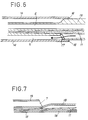
- the proximal parts 1a and 1c are tightly connected to each other by the intermediate part 1b, as will be explained in more detail with reference to FIGS. 6 and 7.
- the body 1 also comprises a core 11 with a high elastic modulus which is fixedly connected at one end 12 to the proximal part 1a and embedded at its other end 13 in the wall defining the second conduit internal 6 at the intermediate part 1b, beyond the opening 7 towards the distal end of said catheter.
- the core 11 can extend over a major portion of the part intermediate to a point in the immediate vicinity of the portion forming a balloon, which guarantees efficient transmission of the thrust exercised in the proximal part up to the distal part.
- connection of the core 11 to the proximal end of the catheter is made at the connector element 3, for example by bonding or welding on the latter.
- the end 12 of the core 11 will be folded into a U in order to link the core 11 to the connector element 3.
- the core 11 has a cross section for example circular, which decreases from its proximal end 12 towards its end distal 13.
- the distal end 13 is preferably in the vicinity immediately and upstream of the above-mentioned balloon portion 2.
- the deformable wall radially forming a balloon 2 of the distal part 1c is extended by a external tube 14 which extends over a portion of the intermediate part 1b.
- the second internal conduit 6 which is coaxial relative to the tube external 14 is obtained by stretching a multi-channel tube 15 on the distal side, extending said outer tube 14 on the proximal side.
- the tube 15 is a double-track tube.
- this tube 15 has in its part a track with a substantially circular cross section which, once stretched constitutes the second internal conduit 6 for passage of the guide wire 8, and in its lower part a second channel having a cross section substantially in the shape of a "crescent moon” or bean which gradually disappears by stretching (see Figure 3).
- the metallic core 11 is disposed in the second channel, and as it is understood, remains embedded at its distal end in the wall of the tube constituting the second internal conduit 6 after stretching, preferably on a major portion of the intermediate part.
- the outer tube 14 is fixed at its proximal end 16 to the tube double tracks 15, preferably by heat sealing.
- An opening 17 is made at the level of the narrowing in the lower part of the double track tube 15 so as to constitute a passageway for the fluid intended for inflating and deflating the ball.
- the proximal part 1a is constituted by a hollow tube 18 to the interior of which is disposed the core 11.
- the distal end of the tube 18 is slightly crushed to form a track whose cross section is substantially identical to that of the aforementioned lower track of the tube 15.
- the junction is made by contacting and welding the tubes 15 and 18 previously arranged so as to coincide the lower track of the double track tube 15 and the track formed at the end distal previously crushed from the tube 18.
- the junction thus obtained is waterproof.
- the aforementioned opening 7 is produced by cutting off the end proximal of the double-track tube 15, the crushed upper part of the tube 18 constituting the aforementioned ramp for guiding the wire 8 towards the outside of the catheter.
- a guide catheter will first introduced into the patient's vessel.
- a dilation catheter according to the present invention of suitable size previously selected and a guide wire 8 will be introduced into this guide catheter by initial advance of the wire guidance to the stenosis, then in advance of the dilatation catheter until balloon 2 is opposite the stenosis.
Landscapes
- Health & Medical Sciences (AREA)
- Heart & Thoracic Surgery (AREA)
- Life Sciences & Earth Sciences (AREA)
- Anesthesiology (AREA)
- Hematology (AREA)
- Biophysics (AREA)
- Pulmonology (AREA)
- Engineering & Computer Science (AREA)
- Vascular Medicine (AREA)
- Biomedical Technology (AREA)
- Child & Adolescent Psychology (AREA)
- Animal Behavior & Ethology (AREA)
- General Health & Medical Sciences (AREA)
- Public Health (AREA)
- Veterinary Medicine (AREA)
- Media Introduction/Drainage Providing Device (AREA)
- Materials For Medical Uses (AREA)
- Acyclic And Carbocyclic Compounds In Medicinal Compositions (AREA)
Description
- un corps tubulaire flexible comprenant une partie distale, une partie intermédiaire et une partie proximale, et comportant :
- une portion déformable radialement formant ballon, disposée au niveau de sa partie distale ;
- un premier conduit interne débouchant à une extrémité à l'intérieur du ballon, de façon étanche, et reliée à l'autre extrémité à une source d'alimentation en fluide pour permettre le gonflage et le dégonflage du ballon ;
- un second conduit interne, non communiquant avec ledit premier conduit interne, traversant ladite partie distale, et comportant une ouverture au niveau de la partie intermédiaire et au voisinage de la partie proximale, ledit conduit étant défini par une paroi sensiblement tubulaire et adapté pour permettre le passage d'un fil-guide sortant dudit second conduit interne par ladite ouverture, ledit corps comportant en outre une âme présentant un module élastique d'au moins 10000 Mpa reliée fixement à une extrémité à la partie proximale et noyée à son autre extrémité dans la paroi précitée définissant ledit second conduit interne.
- un corps tubulaire flexible comprenant une partie distale, une partie intermédiaire et une partie proximale, et comportant :
- une portion déformable radialement formant ballon, disposée au niveau de sa partie distale ;
- un premier conduit interne débouchant à une extrémité à l'intérieur du ballon, de façon étanche, et reliée à l'autre extrémité à une source d'alimentation en fluide pour permettre le gonflage et le dégonflage du ballon ;
- un second conduit interne, non communiquant avec ledit premier conduit interne, traversant ladite partie distale, et comportant une ouverture au niveau de la partie intermédiaire et au voisinage de la partie proximale, ledit conduit étant défini par une paroi sensiblement tubulaire et adapté pour permettre le passage d'un fil-guide sortant dudit second conduit interne par ladite ouverture, ledit corps comportant en outre une âme présentant un module élastique d'au moins 10000 Mpa reliée fixement à une extrémité à la partie proximale et noyée à son autre extrémité dans la paroi précitée définissant ledit second conduit interne, caractérisé en ce que ladite âme s'étend au-delà de ladite ouverture en direction de l'extrémité distale dudit cathéter.
- une partie proximale, constituée par un tube creux (18) dont l'extrémité distale est légèrement écrasée ;
- une partie distale comprenant un conduit interne sensiblement axial formant la partie distale du second conduit interne précité et un tube externe entourant de façon coaxiale ledit tube interne et comportant une portion déformable radialement formant ballon;
- une partie intermédiaire réalisant une jonction étanche entre les parties proximale et distale comprenant un tube externe prolongeant le tube externe précité de la partie distale et relié à son extrémité proximale à un tube double voies dont la partie distale a été étirée pour former un conduit interne prolongeant de façon étanche le conduit interne de la partie distale précitée.
- la figure 1 est une vue en coupe longitudinale d'un cathéter de dilatation à échange rapide conforme à la présente invention ;
- la figure 2 est une vue en coupe transversale selon la ligne II-II de la figure 1 ;
- la figure 3 est une vue en coupe transversale selon la ligne III-III de la figure 1 ;
- la figure 4 est une vue en coupe transversale selon la ligne IV-IV de la figure 1 ;
- la figure 5 est une vue en coupe transversale selon la ligne V-V de la figure 1 ;
- la figure 6 est une vue de détail en coupe longitudinale montrant la portion sensiblement centrale de la partie intermédiaire d'un cathéter de dilatation conforme à la présente invention ; et
- la figure 7 est une vue de détail en coupe longitudinale montrant la jonction entre les parties intermédiaire et proximale d'un cathéter de dilation conforme à la présente invention.
Claims (7)
- Cathéter de dilatation à échange rapide, destiné à être introduit dans un canal corporel tel que notamment un vaisseau sanguin, comprenant :un corps tubulaire flexible (1) comprenant une partie distale (1c), une partie intermédiaire (1b) et une partie proximale (1a), et comportant :une portion déformable radialement formant ballon (2), disposée au niveau de sa partie distale ;un premier conduit interne (5) débouchant à une extrémité à l'intérieur du ballon, de façon étanche, et reliée à l'autre extrémité à une source d'alimentation en fluide pour permettre le gonflage et le dégonflage du ballon ;un second conduit interne (6), non communiquant avec ledit premier conduit interne (5), traversant ladite partie distale, et comportant une ouverture (7) au niveau de la partie intermédiaire et au voisinage de la partie proximale, ledit conduit étant défini par une paroi sensiblement tubulaire et adapté pour permettre le passage d'un fil-guide (8) sortant dudit second conduit interne (6) par ladite ouverture (7), ledit corps comportant en outre une âme (11) présentant un module élastique d'au moins 10000 Mpa reliée fixement à une extrémité (12) à la partie proximale et noyée à son autre extrémité (13) dans la paroi précitée définissant ledit second conduit interne, caractérisé en ce que ladite âme s'étend au-delà de ladite ouverture (7) en direction de l'extrémité distale dudit cathéter.
- Cathéter de dilatation à échange rapide selon la revendication 1, caractérisé en ce que l'âme (11) précitée présente une section transversale qui décroit de son extrémité proximale vers son extrémité distale.
- Cathéter de dilatation à échange rapide, selon la revendication 1 ou 2, caractérisé en ce que l'âme (11) précitée est métallique, notamment en acier.
- Cathéter de dilatation à échange rapide selon l'une des revendications 1 à 3, caractérisé en ce que l'âme (11) précitée s'étend dans la partie intermédiaire jusqu'à un point situé au voisinage immédiat de la portion formant ballon.
- Cathéter de dilatation à échange rapide selon l'une des revendications 1 à 4, caractérisé en ce que le second conduit interne (6) précité présente, au niveau de son extrémité débouchant à l'intérieur du cathéter, la forme d'une rampe destinée à guider le fil (8) vers l'extérieur du cathéter.
- Cathéter de dilatation selon l'une des revendications 1 à 5, caractérisé en ce que le corps tubulaire flexible (1) précité comprend :une partie proximale (1a), constituée par un tube creux (18) dont l'extrémité distale est légèrement écrasée ;une partie distale (1c) comprenant un conduit interne sensiblement axial formant la partie distale du second conduit interne (6) précité et un tube externe entourant de façon coaxiale ledit tube interne et comportant une portion déformable radialement formant ballon (2) ;une partie intermédiaire (1b) réalisant une jonction étanche entre les parties proximale (1a) et distale (1c) comprenant un tube externe (14) prolongeant le tube externe précité de la partie distale et relié à son extrémité proximale à un tube double voies (15) dont la partie distale a été étirée pour former un conduit interne prolongeant de façon étanche le conduit interne de la partie distale précitée.
- Cathéter de dilatation à échange rapide selon l'une des revendications précédentes, caractérisé en ce que l'âme (11) précitée comporte une extrémité proximale pliée en U.
Applications Claiming Priority (3)
| Application Number | Priority Date | Filing Date | Title |
|---|---|---|---|
| FR9404497A FR2718645B1 (fr) | 1994-04-15 | 1994-04-15 | Cathéter de dilatation à échange rapide. |
| FR9404497 | 1994-04-15 | ||
| PCT/FR1995/000472 WO1995028197A1 (fr) | 1994-04-15 | 1995-04-12 | Catheter de dilatation a echange rapide |
Publications (2)
| Publication Number | Publication Date |
|---|---|
| EP0755281A1 EP0755281A1 (fr) | 1997-01-29 |
| EP0755281B1 true EP0755281B1 (fr) | 1998-03-18 |
Family
ID=9462133
Family Applications (1)
| Application Number | Title | Priority Date | Filing Date |
|---|---|---|---|
| EP95917382A Expired - Lifetime EP0755281B1 (fr) | 1994-04-15 | 1995-04-12 | Catheter de dilatation a echange rapide |
Country Status (11)
| Country | Link |
|---|---|
| US (1) | US5545134A (fr) |
| EP (1) | EP0755281B1 (fr) |
| JP (1) | JPH10503386A (fr) |
| AT (1) | ATE164089T1 (fr) |
| AU (1) | AU2347495A (fr) |
| CA (1) | CA2187671A1 (fr) |
| DE (1) | DE69501822T2 (fr) |
| ES (1) | ES2116747T3 (fr) |
| FR (1) | FR2718645B1 (fr) |
| NO (1) | NO964364L (fr) |
| WO (1) | WO1995028197A1 (fr) |
Families Citing this family (100)
| Publication number | Priority date | Publication date | Assignee | Title |
|---|---|---|---|---|
| CA2142992A1 (fr) | 1992-08-25 | 1994-03-03 | Thomas Fitzmaurice | Catheter de dilatation a fil de renforcement |
| US20020177841A1 (en) * | 1992-08-25 | 2002-11-28 | Noreen Moloney | Dilatation catheter with stiffening wire |
| JP3713048B2 (ja) * | 1994-12-27 | 2005-11-02 | アドバンスト・カーディオバスキュラー・システムズ・インコーポレイテッド | 補強された長円形状の横断面を備えたカテーテル |
| US5667493A (en) * | 1994-12-30 | 1997-09-16 | Janacek; Jaroslav | Dilation catheter |
| EP0757570B1 (fr) * | 1995-02-24 | 2003-06-18 | Ave Connaught | Catheter renforce a ballonet du type echange rapide |
| US5749851A (en) * | 1995-03-02 | 1998-05-12 | Scimed Life Systems, Inc. | Stent installation method using balloon catheter having stepped compliance curve |
| FR2736270B1 (fr) * | 1995-07-06 | 1998-01-09 | Nycomed Lab Sa | Catheter de dilatation du type guide sur un fil |
| FR2748212B1 (fr) * | 1996-05-06 | 1998-07-31 | Nycomed Lab Sa | Catheter destine a la delivrance locale d'une substance therapeutiquement active |
| US6605057B2 (en) * | 1996-10-24 | 2003-08-12 | Medtronic Ave, Inc. | Reinforced monorail balloon catheter |
| US5690613A (en) | 1996-12-06 | 1997-11-25 | Medtronic, Inc. | Rapid exchange high pressure transition for high pressure catheter with non-compliant balloon |
| US20030233068A1 (en) * | 1997-09-18 | 2003-12-18 | Swaminathan Jayaraman | Delivery mechanism for balloons, drugs, stents and other physical/mechanical agents and method of use |
| US6592548B2 (en) | 1997-09-18 | 2003-07-15 | Iowa-India Investments Company Limited Of Douglas | Delivery mechanism for balloons, drugs, stents and other physical/mechanical agents and method of use |
| US6056722A (en) * | 1997-09-18 | 2000-05-02 | Iowa-India Investments Company Limited Of Douglas | Delivery mechanism for balloons, drugs, stents and other physical/mechanical agents and methods of use |
| US6475187B1 (en) | 1998-03-04 | 2002-11-05 | Scimed Life Systems, Inc. | Convertible catheter incorporating distal force transfer mechanism |
| US6419643B1 (en) | 1998-04-21 | 2002-07-16 | Alsius Corporation | Central venous catheter with heat exchange properties |
| US8128595B2 (en) | 1998-04-21 | 2012-03-06 | Zoll Circulation, Inc. | Method for a central venous line catheter having a temperature control system |
| US6368304B1 (en) | 1999-02-19 | 2002-04-09 | Alsius Corporation | Central venous catheter with heat exchange membrane |
| IT1300577B1 (it) * | 1998-05-29 | 2000-05-23 | Invatec Srl | Struttura di catetere di dilatazione |
| DE69928827T2 (de) * | 1998-10-29 | 2006-08-31 | Medtronic MiniMed, Inc., Northridge | Reservoiranschluss |
| US6582398B1 (en) | 1999-02-19 | 2003-06-24 | Alsius Corporation | Method of managing patient temperature with a heat exchange catheter |
| US6299599B1 (en) | 1999-02-19 | 2001-10-09 | Alsius Corporation | Dual balloon central venous line catheter temperature control system |
| JP3909991B2 (ja) * | 1999-11-26 | 2007-04-25 | テルモ株式会社 | カテーテル |
| US6589207B1 (en) | 1999-12-21 | 2003-07-08 | Advanced Cardiovascular Systems, Inc. | Rapid exchange catheter having a support mandrel |
| US7118551B1 (en) | 1999-12-22 | 2006-10-10 | Advanced Cardiovascular Systems, Inc. | Non-metal reinforcing mandrel |
| US20030055377A1 (en) * | 2000-06-02 | 2003-03-20 | Avantec Vascular Corporation | Exchangeable catheter |
| US6569180B1 (en) | 2000-06-02 | 2003-05-27 | Avantec Vascular Corporation | Catheter having exchangeable balloon |
| US7238168B2 (en) * | 2000-06-02 | 2007-07-03 | Avantec Vascular Corporation | Exchangeable catheter |
| US6663648B1 (en) * | 2000-06-15 | 2003-12-16 | Cordis Corporation | Balloon catheter with floating stiffener, and procedure |
| JP4490559B2 (ja) * | 2000-06-23 | 2010-06-30 | 川澄化学工業株式会社 | バルーンカテーテル |
| US6592549B2 (en) * | 2001-03-14 | 2003-07-15 | Scimed Life Systems, Inc. | Rapid exchange stent delivery system and associated components |
| US6679909B2 (en) * | 2001-07-31 | 2004-01-20 | Advanced Cardiovascular Systems, Inc. | Rapid exchange delivery system for self-expanding stent |
| US6979342B2 (en) | 2001-09-19 | 2005-12-27 | Advanced Cardiovascular Systems, Incc | Catheter with a polyimide distal tip |
| US6863678B2 (en) * | 2001-09-19 | 2005-03-08 | Advanced Cardiovascular Systems, Inc. | Catheter with a multilayered shaft section having a polyimide layer |
| US7229431B2 (en) * | 2001-11-08 | 2007-06-12 | Russell A. Houser | Rapid exchange catheter with stent deployment, therapeutic infusion, and lesion sampling features |
| US6572640B1 (en) | 2001-11-21 | 2003-06-03 | Alsius Corporation | Method and apparatus for cardiopulmonary bypass patient temperature control |
| US9949829B2 (en) | 2002-06-13 | 2018-04-24 | Ancora Heart, Inc. | Delivery devices and methods for heart valve repair |
| US7753922B2 (en) | 2003-09-04 | 2010-07-13 | Guided Delivery Systems, Inc. | Devices and methods for cardiac annulus stabilization and treatment |
| US9226825B2 (en) * | 2002-06-13 | 2016-01-05 | Guided Delivery Systems, Inc. | Delivery devices and methods for heart valve repair |
| US20060122633A1 (en) | 2002-06-13 | 2006-06-08 | John To | Methods and devices for termination |
| US20050216078A1 (en) * | 2002-06-13 | 2005-09-29 | Guided Delivery Systems, Inc. | Delivery devices and methods for heart valve repair |
| US8641727B2 (en) | 2002-06-13 | 2014-02-04 | Guided Delivery Systems, Inc. | Devices and methods for heart valve repair |
| EP1530441B1 (fr) | 2002-06-13 | 2017-08-02 | Ancora Heart, Inc. | Dispositifs et procedes de reparation de valvule cardiaque |
| US7588582B2 (en) | 2002-06-13 | 2009-09-15 | Guided Delivery Systems Inc. | Methods for remodeling cardiac tissue |
| US7758637B2 (en) | 2003-02-06 | 2010-07-20 | Guided Delivery Systems, Inc. | Delivery devices and methods for heart valve repair |
| US7753858B2 (en) | 2002-06-13 | 2010-07-13 | Guided Delivery Systems, Inc. | Delivery devices and methods for heart valve repair |
| US8287555B2 (en) | 2003-02-06 | 2012-10-16 | Guided Delivery Systems, Inc. | Devices and methods for heart valve repair |
| US7666193B2 (en) * | 2002-06-13 | 2010-02-23 | Guided Delivery Sytems, Inc. | Delivery devices and methods for heart valve repair |
| US7883538B2 (en) | 2002-06-13 | 2011-02-08 | Guided Delivery Systems Inc. | Methods and devices for termination |
| US6837870B2 (en) * | 2002-07-23 | 2005-01-04 | Advanced Cardiovascular Systems, Inc. | Catheter having a multilayered shaft section with a reinforcing mandrel |
| US7278984B2 (en) | 2002-12-31 | 2007-10-09 | Alsius Corporation | System and method for controlling rate of heat exchange with patient |
| US8211087B2 (en) * | 2003-07-31 | 2012-07-03 | Cook Medical Technologies Llc | Distal wire stop |
| US7534204B2 (en) * | 2003-09-03 | 2009-05-19 | Guided Delivery Systems, Inc. | Cardiac visualization devices and methods |
| US7867271B2 (en) | 2003-11-20 | 2011-01-11 | Advanced Cardiovascular Systems, Inc. | Rapid-exchange delivery systems for self-expanding stents |
| US7022104B2 (en) | 2003-12-08 | 2006-04-04 | Angioscore, Inc. | Facilitated balloon catheter exchange |
| JP4535868B2 (ja) | 2004-12-28 | 2010-09-01 | テルモ株式会社 | カテーテル |
| WO2006113863A2 (fr) * | 2005-04-20 | 2006-10-26 | Cook Incorporated | Appareil medical pour insertion rapide |
| WO2006113866A2 (fr) * | 2005-04-20 | 2006-10-26 | Cook Incorporated | Joint interne pour dispositifs medicaux |
| WO2006113869A2 (fr) * | 2005-04-20 | 2006-10-26 | Cook Incorporated | Joint a canule interne pour systemes de mise en place de dispositifs medicaux |
| JP5033118B2 (ja) * | 2005-04-20 | 2012-09-26 | クック メディカル テクノロジーズ エルエルシー | テーパ状構成部品を有する医療用送達機器 |
| DE602006012464D1 (de) * | 2005-04-20 | 2010-04-08 | Cook Inc | Schmelzgebundenes gelenk für medizinprodukt |
| US20070142821A1 (en) * | 2005-12-16 | 2007-06-21 | Medtronic Vascular, Inc. | Rapid exchange catheter having a uniform diameter exchange joint |
| US7906066B2 (en) | 2006-06-30 | 2011-03-15 | Abbott Cardiovascular Systems, Inc. | Method of making a balloon catheter shaft having high strength and flexibility |
| US8382738B2 (en) | 2006-06-30 | 2013-02-26 | Abbott Cardiovascular Systems, Inc. | Balloon catheter tapered shaft having high strength and flexibility and method of making same |
| US9339632B2 (en) * | 2006-09-27 | 2016-05-17 | Boston Scientific Scimed, Inc. | Catheter shaft designs |
| JP5332184B2 (ja) * | 2007-11-16 | 2013-11-06 | 住友ベークライト株式会社 | 腸管内挿入用カテーテル |
| US8403885B2 (en) | 2007-12-17 | 2013-03-26 | Abbott Cardiovascular Systems Inc. | Catheter having transitioning shaft segments |
| WO2009086099A2 (fr) * | 2007-12-20 | 2009-07-09 | Bayer Schering Pharma Ag | Cathéter à fil central et liaisons de faible section |
| AU2009212393B2 (en) | 2008-02-06 | 2014-07-24 | Ancora Heart, Inc. | Multi-window guide tunnel |
| CN102245110A (zh) | 2008-10-10 | 2011-11-16 | 导向传输系统股份有限公司 | 系绳张紧装置及相关方法 |
| CN102245109A (zh) | 2008-10-10 | 2011-11-16 | 导向传输系统股份有限公司 | 终止装置和相关方法 |
| US8052638B2 (en) | 2008-11-26 | 2011-11-08 | Abbott Cardiovascular Systems, Inc. | Robust multi-layer balloon |
| US8444608B2 (en) | 2008-11-26 | 2013-05-21 | Abbott Cardivascular Systems, Inc. | Robust catheter tubing |
| WO2010085456A1 (fr) | 2009-01-20 | 2010-07-29 | Guided Delivery Systems Inc. | Dispositifs de déploiement d'ancrage et procédés apparentés |
| JP4963327B2 (ja) | 2010-06-11 | 2012-06-27 | 朝日インテック株式会社 | バルーンカテーテルの保管装置 |
| US9861350B2 (en) | 2010-09-03 | 2018-01-09 | Ancora Heart, Inc. | Devices and methods for anchoring tissue |
| CN103179914B (zh) | 2010-10-25 | 2016-11-09 | 美敦力Af卢森堡有限责任公司 | 用于肾神经调节的微波导管设备 |
| US20120136344A1 (en) | 2010-10-26 | 2012-05-31 | Medtronic Ardian Luxembourg S.A.R.L. | Neuromodulation cryotherapeutic devices and associated systems and methods |
| WO2012162661A1 (fr) | 2011-05-26 | 2012-11-29 | Abbott Cardiovascular Systems Inc. | Bout traversant pour un cathéter |
| US10849771B2 (en) | 2011-06-27 | 2020-12-01 | Boston Scientific Scimed, Inc. | Stent delivery systems and methods for making and using stent delivery systems |
| KR101396017B1 (ko) * | 2011-08-22 | 2014-05-27 | 연세대학교 산학협력단 | 풍선 카테터 |
| EP2768568B1 (fr) | 2011-10-18 | 2020-05-06 | Boston Scientific Scimed, Inc. | Cathéter à ballonnet à traversée intégrée |
| JP2013106797A (ja) * | 2011-11-21 | 2013-06-06 | Nipro Corp | バルーンカテーテル |
| JP6124142B2 (ja) * | 2011-11-21 | 2017-05-10 | ニプロ株式会社 | バルーンカテーテル |
| US8684963B2 (en) | 2012-07-05 | 2014-04-01 | Abbott Cardiovascular Systems Inc. | Catheter with a dual lumen monolithic shaft |
| JP6003384B2 (ja) * | 2012-08-14 | 2016-10-05 | ニプロ株式会社 | カテーテル |
| WO2014141440A1 (fr) | 2013-03-14 | 2014-09-18 | テルモ株式会社 | Cathéter à ballonnet |
| EP2801385A1 (fr) * | 2013-05-07 | 2014-11-12 | Imds R&D Bv | Cathéter à ballonnet |
| JP6207902B2 (ja) * | 2013-07-09 | 2017-10-04 | 株式会社グッドマン | カテーテル |
| JP5896478B2 (ja) * | 2013-09-24 | 2016-03-30 | 朝日インテック株式会社 | バルーンカテーテル |
| US10080865B2 (en) * | 2014-01-14 | 2018-09-25 | Cook Medical Technologies Llc | Multi-lumen catheters for small body vessel applications |
| JP5888755B2 (ja) * | 2014-02-24 | 2016-03-22 | 朝日インテック株式会社 | カテーテル |
| JP6304886B2 (ja) * | 2014-10-28 | 2018-04-04 | 日本ライフライン株式会社 | バルーンカテーテル |
| WO2016141358A1 (fr) | 2015-03-05 | 2016-09-09 | Guided Delivery Systems Inc. | Dispositifs et procédés de visualisation et de détermination de profondeur de pénétration dans un tissu cardiaque |
| US10980973B2 (en) | 2015-05-12 | 2021-04-20 | Ancora Heart, Inc. | Device and method for releasing catheters from cardiac structures |
| EP4635452A3 (fr) | 2016-11-18 | 2025-12-24 | Ancora Heart, Inc. | Dispositif de partage de charge d'implant myocardique pour favoriser une fonction lv |
| KR20210003249A (ko) * | 2018-06-04 | 2021-01-11 | 니혼라이프라인 가부시키가이샤 | 벌룬 카테터 |
| EP3586899B1 (fr) * | 2018-06-25 | 2026-04-22 | Biotronik Ag | Cathéter, en particulier cathéter à ballonnet ainsi que procédé de fabrication de cathéter |
| EP4585164A3 (fr) | 2019-07-15 | 2025-08-27 | Ancora Heart, Inc. | Dispositifs de coupe d'attache |
| JP2022017978A (ja) * | 2020-07-14 | 2022-01-26 | 朝日インテック株式会社 | カテーテル |
| CN114010921A (zh) * | 2021-12-10 | 2022-02-08 | 深圳北芯生命科技股份有限公司 | 延长指引导管 |
Family Cites Families (7)
| Publication number | Priority date | Publication date | Assignee | Title |
|---|---|---|---|---|
| US5112304A (en) * | 1989-03-17 | 1992-05-12 | Angeion Corporation | Balloon catheter |
| US5364357A (en) * | 1989-09-25 | 1994-11-15 | Schneider (Usa) Inc. | Small diameter dilatation catheter having wire reinforced coaxial tubular body |
| US5324269A (en) * | 1991-09-19 | 1994-06-28 | Baxter International Inc. | Fully exchangeable dual lumen over-the-wire dilatation catheter with rip seam |
| US5338295A (en) * | 1991-10-15 | 1994-08-16 | Scimed Life Systems, Inc. | Dilatation catheter with polyimide-encased stainless steel braid proximal shaft |
| CA2142992A1 (fr) * | 1992-08-25 | 1994-03-03 | Thomas Fitzmaurice | Catheter de dilatation a fil de renforcement |
| US5370615A (en) * | 1992-12-28 | 1994-12-06 | Cordis Corporation | Balloon catheter for angioplasty |
| US5382234A (en) * | 1993-04-08 | 1995-01-17 | Scimed Life Systems, Inc. | Over-the-wire balloon catheter |
-
1994
- 1994-04-15 FR FR9404497A patent/FR2718645B1/fr not_active Expired - Fee Related
- 1994-10-27 US US08/330,028 patent/US5545134A/en not_active Expired - Fee Related
-
1995
- 1995-04-12 JP JP7526762A patent/JPH10503386A/ja active Pending
- 1995-04-12 DE DE69501822T patent/DE69501822T2/de not_active Expired - Fee Related
- 1995-04-12 AT AT95917382T patent/ATE164089T1/de active
- 1995-04-12 ES ES95917382T patent/ES2116747T3/es not_active Expired - Lifetime
- 1995-04-12 EP EP95917382A patent/EP0755281B1/fr not_active Expired - Lifetime
- 1995-04-12 CA CA002187671A patent/CA2187671A1/fr not_active Abandoned
- 1995-04-12 AU AU23474/95A patent/AU2347495A/en not_active Abandoned
- 1995-04-12 WO PCT/FR1995/000472 patent/WO1995028197A1/fr not_active Ceased
-
1996
- 1996-10-14 NO NO964364A patent/NO964364L/no unknown
Also Published As
| Publication number | Publication date |
|---|---|
| AU2347495A (en) | 1995-11-10 |
| FR2718645A1 (fr) | 1995-10-20 |
| WO1995028197A1 (fr) | 1995-10-26 |
| EP0755281A1 (fr) | 1997-01-29 |
| NO964364L (no) | 1996-12-11 |
| JPH10503386A (ja) | 1998-03-31 |
| ATE164089T1 (de) | 1998-04-15 |
| FR2718645B1 (fr) | 1996-07-12 |
| DE69501822T2 (de) | 1998-10-08 |
| US5545134A (en) | 1996-08-13 |
| DE69501822D1 (de) | 1998-04-23 |
| ES2116747T3 (es) | 1998-07-16 |
| NO964364D0 (no) | 1996-10-14 |
| CA2187671A1 (fr) | 1995-10-26 |
Similar Documents
| Publication | Publication Date | Title |
|---|---|---|
| EP0755281A1 (fr) | Catheter de dilatation a echange rapide | |
| EP0621793B1 (fr) | Catheter de dilatation | |
| EP0327431B1 (fr) | Sonde destinée à être introduite à l'intérieur d'un corps vivant | |
| EP1315458B1 (fr) | Dispositif d'occlusion vasculaire et appareil d'utilisation | |
| EP0836504B1 (fr) | Catheter de dilatation du type guide sur un fil | |
| EP0897309B1 (fr) | Catheter destine notamment a la delivrance locale d'une substance therapeutiquement active | |
| FR2729862A1 (fr) | Cathter de dilatation a ouverture laterale | |
| FR2704434A1 (fr) | Ensemble intravasculaire à cathéter. | |
| FR2701401A1 (fr) | Dispositif d'angioplastie. | |
| EP0748241A1 (fr) | Catheter de dilatation a echange rapide | |
| WO1997021400A1 (fr) | Dispositif d'implantation d'une endoprothese vasculaire | |
| FR2733689A1 (fr) | Systeme pour la dilatation de vaisseaux sanguins | |
| FR2852251A1 (fr) | Catheter renforce par un fil possedant une limite apparente d'elasticite elevee. | |
| FR2773717A1 (fr) | Catheter pour canal corporel | |
| EP0974375B1 (fr) | Dispositif à ballonnet à diamètre nominal ajustable | |
| JP2010035660A (ja) | 医療用バルーンカテーテルおよびステントデリバリーカテーテル | |
| FR2578747A1 (fr) | Catheters de dilatation | |
| FR2738489A1 (fr) | Catheter a ballonnet d'occlusion et son procede de fabrication | |
| EP1684664B1 (fr) | Dispositif formant endoprothese presentant des extremites reduites | |
| FR2597350A1 (fr) | Catheter a ballon. | |
| FR2791550A1 (fr) | Sertisseur pour endoprothese intraluminale destine a sertir une endoprothese sur un ballon | |
| FR2729861A1 (fr) | Catheter, notamment pour l'endoscopie des voies biliaires | |
| FR2669826A1 (fr) | Catheter pour la dilatation des arteres. |
Legal Events
| Date | Code | Title | Description |
|---|---|---|---|
| PUAI | Public reference made under article 153(3) epc to a published international application that has entered the european phase |
Free format text: ORIGINAL CODE: 0009012 |
|
| 17P | Request for examination filed |
Effective date: 19960708 |
|
| AK | Designated contracting states |
Kind code of ref document: A1 Designated state(s): AT BE CH DE DK ES FR GB GR IE IT LI LU MC NL PT SE |
|
| 17Q | First examination report despatched |
Effective date: 19970131 |
|
| GRAG | Despatch of communication of intention to grant |
Free format text: ORIGINAL CODE: EPIDOS AGRA |
|
| GRAG | Despatch of communication of intention to grant |
Free format text: ORIGINAL CODE: EPIDOS AGRA |
|
| GRAH | Despatch of communication of intention to grant a patent |
Free format text: ORIGINAL CODE: EPIDOS IGRA |
|
| GRAH | Despatch of communication of intention to grant a patent |
Free format text: ORIGINAL CODE: EPIDOS IGRA |
|
| GRAA | (expected) grant |
Free format text: ORIGINAL CODE: 0009210 |
|
| AK | Designated contracting states |
Kind code of ref document: B1 Designated state(s): AT BE CH DE DK ES FR GB GR IE IT LI LU MC NL PT SE |
|
| PG25 | Lapsed in a contracting state [announced via postgrant information from national office to epo] |
Ref country code: NL Free format text: LAPSE BECAUSE OF FAILURE TO SUBMIT A TRANSLATION OF THE DESCRIPTION OR TO PAY THE FEE WITHIN THE PRESCRIBED TIME-LIMIT Effective date: 19980318 Ref country code: GR Free format text: LAPSE BECAUSE OF FAILURE TO SUBMIT A TRANSLATION OF THE DESCRIPTION OR TO PAY THE FEE WITHIN THE PRESCRIBED TIME-LIMIT Effective date: 19980318 Ref country code: AT Free format text: LAPSE BECAUSE OF FAILURE TO SUBMIT A TRANSLATION OF THE DESCRIPTION OR TO PAY THE FEE WITHIN THE PRESCRIBED TIME-LIMIT Effective date: 19980318 |
|
| REF | Corresponds to: |
Ref document number: 164089 Country of ref document: AT Date of ref document: 19980415 Kind code of ref document: T |
|
| REG | Reference to a national code |
Ref country code: CH Ref legal event code: EP |
|
| PG25 | Lapsed in a contracting state [announced via postgrant information from national office to epo] |
Ref country code: LU Free format text: LAPSE BECAUSE OF NON-PAYMENT OF DUE FEES Effective date: 19980412 |
|
| REF | Corresponds to: |
Ref document number: 69501822 Country of ref document: DE Date of ref document: 19980423 |
|
| PG25 | Lapsed in a contracting state [announced via postgrant information from national office to epo] |
Ref country code: BE Free format text: LAPSE BECAUSE OF NON-PAYMENT OF DUE FEES Effective date: 19980430 |
|
| ITF | It: translation for a ep patent filed | ||
| PG25 | Lapsed in a contracting state [announced via postgrant information from national office to epo] |
Ref country code: MC Free format text: THE PATENT HAS BEEN ANNULLED BY A DECISION OF A NATIONAL AUTHORITY Effective date: 19980514 |
|
| PG25 | Lapsed in a contracting state [announced via postgrant information from national office to epo] |
Ref country code: SE Free format text: LAPSE BECAUSE OF FAILURE TO SUBMIT A TRANSLATION OF THE DESCRIPTION OR TO PAY THE FEE WITHIN THE PRESCRIBED TIME-LIMIT Effective date: 19980618 Ref country code: PT Free format text: LAPSE BECAUSE OF FAILURE TO SUBMIT A TRANSLATION OF THE DESCRIPTION OR TO PAY THE FEE WITHIN THE PRESCRIBED TIME-LIMIT Effective date: 19980618 Ref country code: DK Free format text: LAPSE BECAUSE OF FAILURE TO SUBMIT A TRANSLATION OF THE DESCRIPTION OR TO PAY THE FEE WITHIN THE PRESCRIBED TIME-LIMIT Effective date: 19980618 |
|
| GBT | Gb: translation of ep patent filed (gb section 77(6)(a)/1977) |
Effective date: 19980618 |
|
| REG | Reference to a national code |
Ref country code: IE Ref legal event code: FG4D Free format text: 79436 |
|
| REG | Reference to a national code |
Ref country code: ES Ref legal event code: FG2A Ref document number: 2116747 Country of ref document: ES Kind code of ref document: T3 |
|
| NLV1 | Nl: lapsed or annulled due to failure to fulfill the requirements of art. 29p and 29m of the patents act | ||
| PG25 | Lapsed in a contracting state [announced via postgrant information from national office to epo] |
Ref country code: IE Free format text: LAPSE BECAUSE OF NON-PAYMENT OF DUE FEES Effective date: 19980924 |
|
| REG | Reference to a national code |
Ref country code: IE Ref legal event code: FD4D Ref document number: 79436 Country of ref document: IE |
|
| BERE | Be: lapsed |
Owner name: S.A. LABORATOIRES NYCOMED Effective date: 19980430 |
|
| PLBE | No opposition filed within time limit |
Free format text: ORIGINAL CODE: 0009261 |
|
| STAA | Information on the status of an ep patent application or granted ep patent |
Free format text: STATUS: NO OPPOSITION FILED WITHIN TIME LIMIT |
|
| 26N | No opposition filed | ||
| PG25 | Lapsed in a contracting state [announced via postgrant information from national office to epo] |
Ref country code: LI Free format text: LAPSE BECAUSE OF NON-PAYMENT OF DUE FEES Effective date: 19990430 Ref country code: CH Free format text: LAPSE BECAUSE OF NON-PAYMENT OF DUE FEES Effective date: 19990430 |
|
| REG | Reference to a national code |
Ref country code: CH Ref legal event code: PL |
|
| REG | Reference to a national code |
Ref country code: GB Ref legal event code: 732E |
|
| REG | Reference to a national code |
Ref country code: ES Ref legal event code: PC2A |
|
| REG | Reference to a national code |
Ref country code: FR Ref legal event code: TP |
|
| REG | Reference to a national code |
Ref country code: GB Ref legal event code: IF02 |
|
| PGFP | Annual fee paid to national office [announced via postgrant information from national office to epo] |
Ref country code: GB Payment date: 20020403 Year of fee payment: 8 |
|
| PGFP | Annual fee paid to national office [announced via postgrant information from national office to epo] |
Ref country code: ES Payment date: 20020416 Year of fee payment: 8 |
|
| PGFP | Annual fee paid to national office [announced via postgrant information from national office to epo] |
Ref country code: FR Payment date: 20020417 Year of fee payment: 8 |
|
| PGFP | Annual fee paid to national office [announced via postgrant information from national office to epo] |
Ref country code: DE Payment date: 20020628 Year of fee payment: 8 |
|
| PG25 | Lapsed in a contracting state [announced via postgrant information from national office to epo] |
Ref country code: GB Free format text: LAPSE BECAUSE OF NON-PAYMENT OF DUE FEES Effective date: 20030412 |
|
| PG25 | Lapsed in a contracting state [announced via postgrant information from national office to epo] |
Ref country code: ES Free format text: LAPSE BECAUSE OF NON-PAYMENT OF DUE FEES Effective date: 20030414 |
|
| PG25 | Lapsed in a contracting state [announced via postgrant information from national office to epo] |
Ref country code: DE Free format text: LAPSE BECAUSE OF NON-PAYMENT OF DUE FEES Effective date: 20031101 |
|
| GBPC | Gb: european patent ceased through non-payment of renewal fee |
Effective date: 20030412 |
|
| PG25 | Lapsed in a contracting state [announced via postgrant information from national office to epo] |
Ref country code: FR Free format text: LAPSE BECAUSE OF NON-PAYMENT OF DUE FEES Effective date: 20031231 |
|
| REG | Reference to a national code |
Ref country code: FR Ref legal event code: ST |
|
| REG | Reference to a national code |
Ref country code: ES Ref legal event code: FD2A Effective date: 20030414 |
|
| PG25 | Lapsed in a contracting state [announced via postgrant information from national office to epo] |
Ref country code: IT Free format text: LAPSE BECAUSE OF NON-PAYMENT OF DUE FEES;WARNING: LAPSES OF ITALIAN PATENTS WITH EFFECTIVE DATE BEFORE 2007 MAY HAVE OCCURRED AT ANY TIME BEFORE 2007. THE CORRECT EFFECTIVE DATE MAY BE DIFFERENT FROM THE ONE RECORDED. Effective date: 20050412 |