EP0754079B1 - Fixation de ski - Google Patents
Fixation de ski Download PDFInfo
- Publication number
- EP0754079B1 EP0754079B1 EP96901185A EP96901185A EP0754079B1 EP 0754079 B1 EP0754079 B1 EP 0754079B1 EP 96901185 A EP96901185 A EP 96901185A EP 96901185 A EP96901185 A EP 96901185A EP 0754079 B1 EP0754079 B1 EP 0754079B1
- Authority
- EP
- European Patent Office
- Prior art keywords
- sole
- jaw
- hollow profile
- down device
- transverse axis
- Prior art date
- Legal status (The legal status is an assumption and is not a legal conclusion. Google has not performed a legal analysis and makes no representation as to the accuracy of the status listed.)
- Expired - Lifetime
Links
- 230000027455 binding Effects 0.000 title claims abstract description 36
- 238000009739 binding Methods 0.000 title claims abstract description 36
- 238000006073 displacement reaction Methods 0.000 claims description 9
- 210000001217 buttock Anatomy 0.000 description 27
- 230000006835 compression Effects 0.000 description 10
- 238000007906 compression Methods 0.000 description 10
- 238000013459 approach Methods 0.000 description 4
- 101100394497 Caenorhabditis elegans toe-1 gene Proteins 0.000 description 3
- 238000011144 upstream manufacturing Methods 0.000 description 3
- 230000000694 effects Effects 0.000 description 2
- 230000036316 preload Effects 0.000 description 2
- 241000593357 Austroderia fulvida Species 0.000 description 1
- 238000009825 accumulation Methods 0.000 description 1
- 230000006978 adaptation Effects 0.000 description 1
- 238000005452 bending Methods 0.000 description 1
- 230000005540 biological transmission Effects 0.000 description 1
- 230000015572 biosynthetic process Effects 0.000 description 1
- 239000000969 carrier Substances 0.000 description 1
- 230000009194 climbing Effects 0.000 description 1
- 238000010276 construction Methods 0.000 description 1
- 230000001419 dependent effect Effects 0.000 description 1
- 210000002414 leg Anatomy 0.000 description 1
- 230000000284 resting effect Effects 0.000 description 1
- 230000000630 rising effect Effects 0.000 description 1
Images


Classifications
-
- A—HUMAN NECESSITIES
- A63—SPORTS; GAMES; AMUSEMENTS
- A63C—SKATES; SKIS; ROLLER SKATES; DESIGN OR LAYOUT OF COURTS, RINKS OR THE LIKE
- A63C9/00—Ski bindings
- A63C9/20—Non-self-releasing bindings with special sole edge holders instead of toe-straps
-
- A—HUMAN NECESSITIES
- A63—SPORTS; GAMES; AMUSEMENTS
- A63C—SKATES; SKIS; ROLLER SKATES; DESIGN OR LAYOUT OF COURTS, RINKS OR THE LIKE
- A63C9/00—Ski bindings
- A63C9/005—Ski bindings with means for adjusting the position of a shoe holder or of the complete binding relative to the ski
-
- A—HUMAN NECESSITIES
- A63—SPORTS; GAMES; AMUSEMENTS
- A63C—SKATES; SKIS; ROLLER SKATES; DESIGN OR LAYOUT OF COURTS, RINKS OR THE LIKE
- A63C9/00—Ski bindings
- A63C9/08—Ski bindings yieldable or self-releasing in the event of an accident, i.e. safety bindings
- A63C9/0807—Ski bindings yieldable or self-releasing in the event of an accident, i.e. safety bindings for both towing and downhill skiing
-
- A—HUMAN NECESSITIES
- A63—SPORTS; GAMES; AMUSEMENTS
- A63C—SKATES; SKIS; ROLLER SKATES; DESIGN OR LAYOUT OF COURTS, RINKS OR THE LIKE
- A63C9/00—Ski bindings
- A63C9/08—Ski bindings yieldable or self-releasing in the event of an accident, i.e. safety bindings
- A63C9/0805—Adjustment of the toe or heel holders; Indicators therefor
Definitions
- the invention relates to a ski binding with a toe that is about a carrier with an adjustably arranged on the carrier in the longitudinal direction of the carrier Buttocks is connected and with the carrier about a transverse axis in the area of the toe piece is pivotable, and with one arranged on the toe piece, sole holder that can be swung out to the side and rests against a side Swinging out on a slidably mounted in the longitudinal direction of the beam supports at least one spring-loaded pressure piece.
- Ski bindings with the buttocks on one of the two binding jaws interconnecting carriers have the advantage that in the Ski binding used does not impair the bending behavior of the ski, if the carrier is attached to the ski so that it cannot move on the toe becomes. It also gives the easy way out of the carrier with the two binding jaws formed unit about a transverse axis in the area of Toe toe pivoted to the shoe to facilitate walking being able to lift off the ski in the heel area without the ski binding to loosen or adjust. For this purpose only needs for the carrier a releasable locking device to be provided with the ski.
- the compression spring determines thus the release force for the toe piece, which is also easy to use Preload of the compression spring can be adjusted. Since this is the pressure piece with the The spring retainer housing accommodates the sole retainer of the toe piece upstream, such a front jaw can only be used for heel lifting a transverse axis can be pivoted when the housing with the pressure piece and the compression spring is arranged separately from the front jaw (US-A 4 088 342), which not only increases the design effort, but also inevitably that Swiveling the front jaw against a displacement of the pressure piece makes the force of the compression spring dependent.
- the invention is therefore based on the object of a ski binding at the outset to improve the type described with simple constructive means so that a advantageous pivoting movement of the two binding jaws and the carrier formed, lightweight unit around a transverse axis in the Area of the toe is ensured without the toe for the Security release to have to store a spring case.
- the invention achieves the object in that the hollow profile Carrier the load spring for the pressure piece and the Spindle of a screw drive to adjust the slidable on the hollow profile guided buttocks in the profile cavity.
- the loading spring for the pressure piece in to accommodate this hollow profile which is a complex front jaw housing superfluous, which is consequently not over the sole hold-down against the ski tip needs to protrude so that the pivot bearing of the toe with the carrier can be easily performed around a transverse axis in the area of the toe.
- a screw drive can be used to adjust the rear jaw lengthways be provided, the spindle also in the hollow profile of the carrier is arranged, so that overall a very compact, weight-saving construction results in the transfer of all safety-related features from immovable stored ski bindings on pivotable about a front transverse axis Tour binding allowed.
- the pressure piece in the hollow profile or in a the hollow profile extending guide of a front jaw housing slidably is mounted, the pivotable about a central pivot axis Sole retainer of the toe piece two on both sides of this pivot axis protruding downwards, resting on the free end face of the pressure piece Carrier approaches.
- the pressure piece is behind the Carrier approaches, so that the front jaw with the sole hold-down after can complete at the front.
- the mode of operation of the safety release of the The toe piece remains unaffected, because the side swings out Sole retainer from the displacement of the pressure piece against the force depends on its load spring.
- the sole hold-down is one transverse axis formed by the head of its pivot axis is pivotable held, with a vertical distance from this head on one of the Swiveling movement of the sole hold-down device depending on the transverse axis from the side swivel angle controlling cams of the front jaw housing supports, so a similar tilting movement for the sole hold-down can be achieved, but with the advantage of a forced control of this tilting movement when swinging out the sole hold-down device because the Sole retainer when swung out sideways by the cam in one Distance from the head of the swivel axis from this axis is what the desired tilting movement of the sole hold-down device around the swivel axis head causes.
- the buttock can be adjusted using a self-locking screw drive adjustable on the hollow profile of the carrier stored.
- the spindle of the screw drive is preferably against one Axial displacement supported in the hollow profile and the associated, the buttocks assigned threaded nut rotatably guided in the hollow profile, at most relative shifts between the hollow profile that increase the bond length and to avoid the spindle.
- the screw drive is used to adjust the the hollow profile slidably guided back cheek in the hollow profile Spring force in the sense of increasing the distance between the two jaws - kept displaceable, so the contact pressure of the buttocks to the Ski boot largely independent of the setting of the screw drive fixed by a spring force or an adaptation to itself, for example changing the length of the sole by means of snow.
- the safety trigger of the buttocks can be in different ways and Way.
- a preferred embodiment is characterized in that that the buttock one in a guide of a buttock housing adjustable in height, pivotable about a transverse axis Sole holding-down device, which on a driver stop one on the buttock housing operating lever pivotally mounted about a transverse axis is supported and by the actuating lever against the force of at least one arranged in the rear jaw housing spring from a closed position in a Open position can be raised.
- the sole holder is held in place by the spring Buttock housing pressed into the closed position. To release the buttocks the sole hold-down device must therefore be raised against this spring force either via the ski boot sole or the operating lever.
- the lifting movement can be carried out with a swiveling movement of the sole hold-down device can be combined to make getting in and out easier.
- the Sole hold-down is about a transverse axis compared to the buttock housing swiveling and is supported on a driver stop of the actuating lever due to its rotational movement over the driver stop initiates a pivoting movement of the sole hold-down device.
- the sole hold-down of the Buttock housing two successive sliding supports in height for the buttock housing that forms against each other with respect to the Transverse axis of the hold-down device are arranged offset in angle.
- the one of these Slide supports prevent the sole hold-down device from swiveling prematurely, while the other slide support the end position of the open Sole holding-down device determined and consequently compared to the first sliding support must have a corresponding angular displacement.
- An exclusive one Movement of the sole hold-down naturally requires one corresponding relative movement of the driver stop of the actuating lever compared to the sole hold-down, which is very easy to construct a corresponding course of the interacting with the driver stop Counterstop of the sole hold-down can be realized.
- the resultant between the two sliding supports Shoulder used to hold the sole hold-down in its open position if the buttock housing forms a corresponding detent, against the shoulder through the in the closing direction on the sole hold-down acting spring is pulled.
- the sole holder shows next to the Hollow profile of the carrier provided locking lugs, which are in the open position of the sole retainer in the path of movement of the shoe sole when getting in protrude into the ski binding, so for an independent closing of the buttocks concerned because the buttocks over the locking lugs through the Ski boot is taken out of the open position until the closing spring is closed Effect comes and presses the sole hold-down in its closed position.
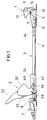
- the ski binding shown consists of a toe 1, a rear jaw 2 and one connecting the two binding jaws 1 and 2 Carrier 3, which by a hollow profile 4, for example with an im essentially rectangular cross section, but a V-shaped bottom 5, as can be seen from FIG.
- the 3 and the unit resulting in the two binding jaws 1, 2 is in a bearing 5 and pivoted about a transverse axis 6 in the region of the front jaw 1 can via a locking device 7 in the drawn basic position be held.
- This locking device 7 encloses an end piece of the hollow profile 4 extended beyond the buttocks 2 with the help of a Locking lever 8, which is pivoted up to unlock the hollow profile 4 must become.
- this locking lever 8 can be used to form climbing aids different heights in different swivel positions Requirements for the hollow profile 4 result.
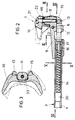
- FIGS. 2 to 4. He consists essentially of a housing forming a sole support 9, to which a laterally displaceable sole plate can be assigned, and from a sole hold-down device 10, which laterally about a central pivot axis 11 is pivotally mounted on the housing 9.
- the hollow profile 4 of the carrier 3 is used in a non-displaceable manner the extension of the housing 9 a sliding guide 12 for an im essential T-shaped pressure piece 13 which engages in the hollow profile 4 and is loaded by a compression spring 14 arranged in the hollow profile 4. over this loading spring 14, the thrust piece 13 on the end face downward protruding driver lugs 15 of the sole retainer 10 pressed.
- the pressure piece 13 is through one of the driver approaches 15 pushed against the force of the load spring 14 into the guide 12, as indicated by dash-dotted lines in FIG. 4.
- the load spring 14 therefore determines the safety trigger for the toe piece 1 required release force.
- the loading spring 14 is a spring sleeve 16th added, which is screw-adjustable relative to the pressure piece 13.
- the spring sleeve 16 is displaceable in the hollow profile 4, but non-rotatably kept because they have an adapted to the cross section of the hollow profile 4 outer Has cross-sectional shape, and with the help of a nut thread of the spring sleeve 16 engaging set screw 17, which is immovable in the pressure piece 13, but is rotatably mounted, displaced relative to the pressure piece 13.
- the set screw 17 is secured against displacement with the aid of locking pins 18 reached, which engage in an annular groove 19 of the screw 17.
- the adjustment screw 17 is the Preload of the load spring 14 and thus the release force for a lateral Swinging out the sole hold-down device 10 is set.
- the sole hold-down 10 is in the Area of the upper head 21 of the pivot axis 11 due to a conical shape downwardly widening passage opening 22 for the pivot axis 11 of the Tiltable height on the front jaw housing 9 stored.
- This tilting movement is controlled depending on the swivel angle because the one receiving the pivot axis 11 against the sole hold-down device 10 protruding housing approach forms a cam 23 which with increasing Swinging out angle of the sole hold-down device 10, its switching off from the Forces pivot axis 11, as can be seen in FIG. 3.
- the sole hold-down device 10 is formed around the pivot axis for this purpose Head 21 from the basic position drawn in full lines in FIG dash-dotted position tilted up, which is dash-dotted in FIG. 3 indicated pivot position of the sole hold-down device 10 corresponds.
- the Sole retainer 10 can, however, despite the forced shutdown during his lateral pivoting against the force of the load spring 14 in the basic position be tipped up, which is an advantageous resilient system on the ski boot sole ensures, for example around snow accumulation on the shoe sole balance.
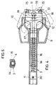
- the rear jaw 2 has an essentially L-shaped housing 24, one of the legs of the hollow profile 4 of the carrier 3 in a sliding guide 25 is enforced.
- the other housing part rising from the carrier 3 receives a compression spring 26 which is located on a guide piece 27 on a Transverse axis 28 supports that in a guide 29 formed by an elongated hole of the housing 24 is guided in height, and the lower storage for a sole hold-down 30, which forms the towering housing part with side cheeks 31 includes.
- the upper support for the sole hold-down 30 is formed by an actuating lever 32 which is about an axis 33 is hinged to the housing 24 and between the housing 24 and the side cheeks 31 of the sole holding-down device 30 has driver stops 34, which with these driver stops 34 overlapping counter-stops 35 to the Side cheeks 31 of the sole hold-down device 30 interact, as shown in FIG. 7 can be removed.
- the actuating lever In the closed position shown in full lines of the buttock 30 is the sole hold-down 30 by the compression spring 26th pressed down as a closing spring, the actuating lever in its pivoted closed position is held. To open the buttocks the sole hold-down device 30 must be raised against the force of the closing spring 26 either via a shoe or the operating lever 32.
- the sole hold-down 30 is initially supported by a slide 36 the housing 24 until this sliding support 36 at the upper end of the towering Housing part a pivoting movement for the sole hold-down 30th releases about the lower transverse axis 28.
- This pivotal movement is controlled by a further slide support 37 limited compared to the slide support 36 is arranged correspondingly offset.
- the pivoting movement of the sole hold-down 30 and the associated rotary movement of the actuating lever 32 is illustrated in FIG. 7, which also shows that the shoulder 38 between the two angularly offset sliding supports 36 and 37 can be used as a rest for the open position of the sole retainer 30 can, if the housing 24 forms a corresponding counter detent against which the Sole hold-down device 30 pulled by the compression spring 26 in the closed position becomes.
- the buttocks must be 2 can be adjusted along the carrier 3.
- a non-shifting Support of the threaded spindle 41 with respect to the hollow profile 4 is thus Buttocks 2 adjusted accordingly.
- the threaded spindle is supported in a non-displaceable manner 41 but via a spring 43, which is on the one hand on one of the Threaded spindle 41 penetrate end piece 44 of the hollow profile 4 and on the other hand is supported on a stop 45 on the threaded spindle 41, so that the Threaded spindle 41 with the buttocks 2 in the sense of increasing the distance the binding jaws move against the force of the spring 43.
- the opening of the binding by hand does not necessarily have to be via the operating lever 32 done.
- the forward accessible pressure piece 13 of the toe piece 1 allows for a corresponding shift against the force its loading spring 14 exemption of the sole hold-down 10, so that the shoe, without having to overcome the trigger force otherwise required the toe piece can be swiveled out.
- Moving the Thrust piece 13 could have a lever upstream of the toe piece can be achieved with a comparatively small force.
- this additional actuator for the pressure piece 13 Actuation by the driver lugs 15 of the sole depressor 10 not be affected.
- the pivot axis 11 can preferably be designed as a set screw.
Landscapes
- Footwear And Its Accessory, Manufacturing Method And Apparatuses (AREA)
- Transition And Organic Metals Composition Catalysts For Addition Polymerization (AREA)
- Magnetic Heads (AREA)
- Die Bonding (AREA)
- Fittings On The Vehicle Exterior For Carrying Loads, And Devices For Holding Or Mounting Articles (AREA)
Claims (6)
- Fixation de ski avec une mâchoire avant (1), qui est reliée, par l'intermédiaire d'un support (3), à un crochet arrière (2) disposé réglable dans la direction longitudinale du support, sur le support (3), et mâchoire avant qui est susceptible de pivoter, à l'aide du support (3), autour d'un axe transversal (6) prévu dans la zone de la mâchoire avant (1), et avec un abaisseur de semelle (10), susceptible de s'écarter par pivotement latéral, disposé sur la mâchoire avant (1) et qui prend appui, pour empêcher un échappement par pivotement latéral, sur une pièce de pressage (13), montée de façon à être déplaçable dans la direction longitudinale du support, chargée par au moins un ressort (14), caractérisée par le fait que le support (3) réalisé sous la forme de profilé creux (4) loge, dans l'espace creux du profilé, le ressort de charge (14), destiné à la pièce de pressage (13) montée dans la mâchoire avant, et la broche filetée (41) d'une transmission à vis (40) destinée au réglage de la mâchoire arrière (2) guidée de façon déplaçable sur le profité creux (4).
- Fixation de ski selon la revendication 1, caractérisée par le fait que la pièce de pressage (13) est montée déplaçable dans le profité creux (4), respectivement dans un guidage (12) prolongeant le profité creux (4) et appartenant à un boítier de mâchoire avant (9), et en ce que l'abaisseur de semelle (10), pouvant s'écarter par pivotement autour d'un axe de pivotement (11) central et appartenant à la mâchoire avant (1), présente deux appendices d'entraínement (15), faisant saillie vers le bas des deux côtés de cet axe de pivotement (11) et appuyant sur la face frontale libre de la pièce de pressage (13).
- Fixation de ski selon la revendication 3, caractérisée par le fait que l'abaisseur de semelle (10) est maintenu de façon à pouvoir pivoter autour d'un axe transversal, constitué par une tête supérieure (21) de son axe de pivotement (11), et prend appui, avec un espacement vertical vis-à-vis de cette tête (21), sur un ergot (23) appartenant au boítier de mâchoire avant (9), qui commande le pivotement de l'abaisseur de semelle autour de l'axe transversal, en fonction de l'angle d'écartement latéral par pivotement.
- Fixation de ski selon l'une des revendications 1 à 3, caractérisée par le fait que la transmission à vis (40), destinée au réglage de la mâchoire arrière (2), guidée de façon déplaçable sur le profilé creux (4), dans le profilé creux (4), est déplaçable à l'encontre de la force de ressort, dans le sens d'une augmentation de l'espacement entre les deux mâchoires de fixation (1, 2).
- Fixation de ski selon l'une des revendications 1 à 4, caractérisée par le fait que la mâchoire arrière (2) présente un abaisseur de semelle (30), réglable en hauteur dans un guidage (29) d'un boítier de mâchoire arrière (24) pouvant pivoter autour d'un axe transversal (28), et qui prend appui sur une butée d'entraínement (34) d'un levier d'actionnement (32) monté pivotant autour d'un axe transversal (33), sur le boítier de mâchoire arrière (24), et susceptible d'être levé à sa position d'ouverture, depuis sa position de fermeture, au moyen du levier d'actionnement (32), à l'encontre de la force d'au moins un ressort (26) disposé dans le boítier de mâchoire arrière (24).
- Fixation de ski selon la revendication 5, caractérisée par le fait que l'abaisseur de semelle (30) de la mâchoire arrière (2) constitue deux appuis coulissants (36, 37) successifs en hauteur, pour le boítier de mâchoire arrière (24), qui sont décalés angulairement l'un par rapport à l'autre, par rapport à l'axe transversal (28) de l'abaisseur de semelle (30).
Applications Claiming Priority (3)
| Application Number | Priority Date | Filing Date | Title |
|---|---|---|---|
| AT170/95 | 1995-02-01 | ||
| AT0017095A AT402796B (de) | 1995-02-01 | 1995-02-01 | Schibindung |
| PCT/AT1996/000013 WO1996023559A1 (fr) | 1995-02-01 | 1996-01-30 | Fixation de ski |
Publications (2)
| Publication Number | Publication Date |
|---|---|
| EP0754079A1 EP0754079A1 (fr) | 1997-01-22 |
| EP0754079B1 true EP0754079B1 (fr) | 1999-04-28 |
Family
ID=3483435
Family Applications (1)
| Application Number | Title | Priority Date | Filing Date |
|---|---|---|---|
| EP96901185A Expired - Lifetime EP0754079B1 (fr) | 1995-02-01 | 1996-01-30 | Fixation de ski |
Country Status (5)
| Country | Link |
|---|---|
| US (1) | US5735541A (fr) |
| EP (1) | EP0754079B1 (fr) |
| AT (2) | AT402796B (fr) |
| DE (1) | DE59601753D1 (fr) |
| WO (1) | WO1996023559A1 (fr) |
Cited By (17)
| Publication number | Priority date | Publication date | Assignee | Title |
|---|---|---|---|---|
| EP1892020A2 (fr) * | 2006-08-25 | 2008-02-27 | MARKER Deutschland GmbH | Agrégat de semelle d'une fixation de ski |
| DE102007013234B3 (de) * | 2007-03-15 | 2008-07-17 | Reinhold Zoor | Skibindung |
| DE102008017969A1 (de) | 2008-04-08 | 2009-10-15 | Reinhold Zoor | Träger für Skibindung |
| EP2181736A1 (fr) | 2008-10-31 | 2010-05-05 | Rottefella AS | talonnière avec deux axes d'ouverture |
| EP2351603A2 (fr) | 2010-01-29 | 2011-08-03 | MARKER Deutschland GmbH | Fixation de ski dotée d'une aide à la montée |
| DE102010028764A1 (de) * | 2010-05-07 | 2011-11-10 | Salewa Sport Ag | Ferseneinheit für eine Bindung, insbesondere Tourenskibindung |
| WO2012024809A1 (fr) | 2010-08-27 | 2012-03-01 | Fritschi Ag - Swiss Bindings | Fixation de ski de randonnée à talonnière comportant une zone de glissement dynamique |
| EP2574379A2 (fr) | 2011-09-29 | 2013-04-03 | Fritschi AG - Swiss Bindings | Automate avant |
| EP2813268A1 (fr) | 2013-06-12 | 2014-12-17 | Fritschi AG - Swiss Bindings | Automate avant |
| EP2965791A1 (fr) | 2014-07-08 | 2016-01-13 | Fritschi AG - Swiss Bindings | Unité de positionnement automatique d'avant de chaussure de skis pour fixation à ergots |
| EP3053632A1 (fr) | 2015-02-03 | 2016-08-10 | Fritschi AG - Swiss Bindings | Talonnière |
| EP3120903A1 (fr) | 2016-10-14 | 2017-01-25 | Fritschi AG - Swiss Bindings | Talonnière |
| EP3266504A1 (fr) | 2016-07-07 | 2018-01-10 | Fritschi AG - Swiss Bindings | Fixation de ski |
| EP3345659A1 (fr) | 2017-01-04 | 2018-07-11 | Fritschi AG - Swiss Bindings | Talonnière automatique pour une fixation de ski |
| EP3566754A1 (fr) | 2018-05-08 | 2019-11-13 | Fritschi AG - Swiss Bindings | Butée avant de fixation de ski |
| EP3581248A1 (fr) | 2018-06-14 | 2019-12-18 | Fritschi AG - Swiss Bindings | Talonnière |
| EP3851174A1 (fr) | 2020-01-16 | 2021-07-21 | Fritschi AG - Swiss Bindings | Butée avant pour une fixation de ski |
Families Citing this family (31)
| Publication number | Priority date | Publication date | Assignee | Title |
|---|---|---|---|---|
| US20030108545A1 (en) * | 1994-02-10 | 2003-06-12 | Patricia Rockwell | Combination methods of inhibiting tumor growth with a vascular endothelial growth factor receptor antagonist |
| US6448077B1 (en) * | 1994-02-10 | 2002-09-10 | Imclone Systems, Inc. | Chimeric and humanized monoclonal antibodies specific to VEGF receptors |
| EP0890378A1 (fr) | 1997-07-07 | 1999-01-13 | Fritschi AG - Swiss Bindings | Fixation de ski |
| EP0890379B2 (fr) | 1997-07-07 | 2007-03-28 | Fritschi AG - Swiss Bindings | Fixation de ski |
| FR2777472B1 (fr) | 1998-04-17 | 2000-07-13 | Salomon Sa | Dispositif interface entre un ski et des elements de retenue d'une chaussure sur le ski |
| FR2786706B1 (fr) | 1998-12-08 | 2001-02-09 | Look Fixations Sa | Fixation de ski |
| EP1022038A1 (fr) | 1999-01-22 | 2000-07-26 | Fritschi AG - Swiss Bindings | Fixation |
| EP1022037A1 (fr) | 1999-01-22 | 2000-07-26 | Fritschi AG - Swiss Bindings | Fixation Telemark |
| FR2789596B1 (fr) | 1999-02-12 | 2001-05-18 | Salomon Sa | Element de retenue arriere d'une chaussure sur un ski et ensemble de retenue comprenant un tel element |
| DE10064095B4 (de) * | 2000-12-21 | 2005-09-08 | Reinhold Zoor | Skibindung |
| JP2005508298A (ja) * | 2001-06-20 | 2005-03-31 | イムクローン システムズ インコーポレイティド | アテローム性動脈硬化症及び他の炎症性疾患を処置する方法 |
| EP1314458A1 (fr) * | 2001-11-23 | 2003-05-28 | HTM Sport- und Freizeitgeräte Aktiengesellschaft | Dispositif d'une fixation de ski réglable en position sur un ski |
| DE50104848D1 (de) | 2001-12-21 | 2005-01-20 | Fritschi Ag Swiss Bindings Rei | Skibindung |
| CA2478169C (fr) * | 2002-03-04 | 2013-04-16 | Imclone Systems Incorporated | Anticorps humains specifiques de kdr et leurs utilisations |
| ATE403474T1 (de) * | 2003-10-30 | 2008-08-15 | Fritschi Ag Swiss Bindings | Skiausrüstung mit harscheisen |
| FR2896428A1 (fr) * | 2006-01-20 | 2007-07-27 | Salomon Sa | Dispositif de fixation d'une chaussure sur une planche de glisse |
| AU2008249766A1 (en) * | 2007-05-15 | 2008-11-20 | Generics [Uk] Limited | Process for the purification of olanzapine |
| CZ2007652A3 (cs) * | 2007-09-18 | 2009-04-08 | Krampla@Milan | Lyžarské vázání |
| DE102008050884A1 (de) * | 2008-10-09 | 2010-04-15 | Marker Deutschland Gmbh | Schuhhalteraggregat einer Skibindung |
| IT1395134B1 (it) * | 2009-08-05 | 2012-09-05 | Ski Trab S R L | Talloniera a piu' posizioni ed aggancio/sgancio facilitato per attacchi da sci alpinistico. |
| US8398110B2 (en) * | 2010-02-01 | 2013-03-19 | Jeannot Morin | Back-country ski binding |
| FR2966747B1 (fr) * | 2010-10-29 | 2013-01-11 | Salomon Sas | Fixation de securite pour la pratique du ski. |
| CH705063A1 (de) * | 2011-05-31 | 2012-12-14 | Fritschi Ag Swiss Bindings | Skibindung. |
| US8827302B2 (en) * | 2012-09-11 | 2014-09-09 | Fritschi Ag-Swiss Bindings | Automatic heel unit for a ski binding |
| DE102013201727A1 (de) * | 2013-02-01 | 2014-08-07 | Marker Deutschland Gmbh | Fersenhalter mit rollenförmigem Sohlenhalter |
| EP3103525B1 (fr) | 2015-06-11 | 2018-12-19 | Fritschi AG - Swiss Bindings | Talonnière |
| US9526971B1 (en) | 2015-09-18 | 2016-12-27 | Rossland Binding Company | Remote release ski binding |
| EP3167943B1 (fr) | 2015-11-12 | 2021-03-10 | Fritschi AG - Swiss Bindings | Talonniere comprenant une structure d'appui de talon |
| EP3195906B1 (fr) | 2016-01-22 | 2018-12-26 | Fritschi AG - Swiss Bindings | Talonniere ayant une configuration de marche |
| US10729968B2 (en) | 2018-05-25 | 2020-08-04 | Rossland Binding Company | Remote release snowboard binding |
| IT202000012502A1 (it) * | 2020-05-27 | 2021-11-27 | Atk Sports S R L | Inserto anteriore per scarpone da sci alpinismo, per l'aggancio dello scarpone ad un attacco da sci alpinismo |
Family Cites Families (9)
| Publication number | Priority date | Publication date | Assignee | Title |
|---|---|---|---|---|
| DE1960489A1 (de) * | 1969-12-02 | 1971-06-09 | Iser Iser Herbert | Sicherheitsbacken fuer Schibindungen |
| DE2348905A1 (de) * | 1973-09-28 | 1975-04-10 | Gerhard Witting | Ausloesebindung |
| AT343522B (de) * | 1975-12-24 | 1978-06-12 | Hausleithner Andreas | Kabellose sicherheitsschibindung |
| CH616591A5 (fr) * | 1976-05-15 | 1980-04-15 | Wunder Kg Heinrich | |
| FR2471795B1 (fr) * | 1979-12-21 | 1985-05-31 | Look Sa | Butee-avant de fixation de ski |
| DE3153703C2 (de) * | 1981-03-13 | 1995-09-14 | Rohrmoser Alois Skifabrik | Skibindung |
| FR2511602A1 (fr) * | 1981-08-20 | 1983-02-25 | Salomon & Fils F | Fixation de securite pour ski |
| AT376139B (de) * | 1983-04-01 | 1984-10-10 | Tyrolia Freizeitgeraete | Fersenhalter |
| ATE132049T1 (de) * | 1992-04-17 | 1996-01-15 | Salomon Sa | Ski mit auflageplatte |
-
1995
- 1995-02-01 AT AT0017095A patent/AT402796B/de not_active IP Right Cessation
-
1996
- 1996-01-30 EP EP96901185A patent/EP0754079B1/fr not_active Expired - Lifetime
- 1996-01-30 US US08/718,314 patent/US5735541A/en not_active Expired - Lifetime
- 1996-01-30 WO PCT/AT1996/000013 patent/WO1996023559A1/fr active IP Right Grant
- 1996-01-30 AT AT96901185T patent/ATE179341T1/de active
- 1996-01-30 DE DE59601753T patent/DE59601753D1/de not_active Expired - Lifetime
Cited By (26)
| Publication number | Priority date | Publication date | Assignee | Title |
|---|---|---|---|---|
| EP1892020A2 (fr) * | 2006-08-25 | 2008-02-27 | MARKER Deutschland GmbH | Agrégat de semelle d'une fixation de ski |
| EP1892020A3 (fr) * | 2006-08-25 | 2008-12-31 | MARKER Deutschland GmbH | dispositif appartenant à une fixation d'une chaussure avec deux bras de levier et un ressort commun |
| US7758062B2 (en) | 2006-08-25 | 2010-07-20 | Marker Deutschland Gmbh | Boot retaining unit of a ski binding |
| EP2540356A3 (fr) * | 2006-08-25 | 2014-06-04 | MARKER Deutschland GmbH | Appareil de maintient d'une fixation de ski avec double bras de maintient et un ressort common |
| DE102007013234B3 (de) * | 2007-03-15 | 2008-07-17 | Reinhold Zoor | Skibindung |
| DE102008017969A1 (de) | 2008-04-08 | 2009-10-15 | Reinhold Zoor | Träger für Skibindung |
| EP2181736A1 (fr) | 2008-10-31 | 2010-05-05 | Rottefella AS | talonnière avec deux axes d'ouverture |
| EP2351603A2 (fr) | 2010-01-29 | 2011-08-03 | MARKER Deutschland GmbH | Fixation de ski dotée d'une aide à la montée |
| DE102010028764A1 (de) * | 2010-05-07 | 2011-11-10 | Salewa Sport Ag | Ferseneinheit für eine Bindung, insbesondere Tourenskibindung |
| WO2012024809A1 (fr) | 2010-08-27 | 2012-03-01 | Fritschi Ag - Swiss Bindings | Fixation de ski de randonnée à talonnière comportant une zone de glissement dynamique |
| DE202011110813U1 (de) | 2010-08-27 | 2016-07-18 | Fritschi Ag Swiss Bindings | Fersenautomat |
| EP2574379A3 (fr) * | 2011-09-29 | 2014-12-31 | Fritschi AG - Swiss Bindings | Automate avant |
| EP2574379A2 (fr) | 2011-09-29 | 2013-04-03 | Fritschi AG - Swiss Bindings | Automate avant |
| US9526973B2 (en) | 2011-09-29 | 2016-12-27 | Fritschi Ag-Swiss Bindings | Ski binding automatic front unit |
| EP3766550A1 (fr) | 2011-09-29 | 2021-01-20 | Fritschi AG - Swiss Bindings | Dispositif automatique avant |
| EP2813268A1 (fr) | 2013-06-12 | 2014-12-17 | Fritschi AG - Swiss Bindings | Automate avant |
| EP2965791A1 (fr) | 2014-07-08 | 2016-01-13 | Fritschi AG - Swiss Bindings | Unité de positionnement automatique d'avant de chaussure de skis pour fixation à ergots |
| EP3053632A1 (fr) | 2015-02-03 | 2016-08-10 | Fritschi AG - Swiss Bindings | Talonnière |
| EP3266504A1 (fr) | 2016-07-07 | 2018-01-10 | Fritschi AG - Swiss Bindings | Fixation de ski |
| EP3120903A1 (fr) | 2016-10-14 | 2017-01-25 | Fritschi AG - Swiss Bindings | Talonnière |
| EP3345659A1 (fr) | 2017-01-04 | 2018-07-11 | Fritschi AG - Swiss Bindings | Talonnière automatique pour une fixation de ski |
| EP3566754A1 (fr) | 2018-05-08 | 2019-11-13 | Fritschi AG - Swiss Bindings | Butée avant de fixation de ski |
| US11338192B2 (en) | 2018-05-08 | 2022-05-24 | Fritschi AG—Swiss Bindings | Automatic front unit for a ski binding |
| EP3581248A1 (fr) | 2018-06-14 | 2019-12-18 | Fritschi AG - Swiss Bindings | Talonnière |
| EP3702005A1 (fr) | 2018-06-14 | 2020-09-02 | Fritschi AG - Swiss Bindings | Talonnière |
| EP3851174A1 (fr) | 2020-01-16 | 2021-07-21 | Fritschi AG - Swiss Bindings | Butée avant pour une fixation de ski |
Also Published As
| Publication number | Publication date |
|---|---|
| EP0754079A1 (fr) | 1997-01-22 |
| US5735541A (en) | 1998-04-07 |
| ATE179341T1 (de) | 1999-05-15 |
| WO1996023559A1 (fr) | 1996-08-08 |
| DE59601753D1 (de) | 1999-06-02 |
| ATA17095A (de) | 1997-01-15 |
| AT402796B (de) | 1997-08-25 |
Similar Documents
| Publication | Publication Date | Title |
|---|---|---|
| EP0754079B1 (fr) | Fixation de ski | |
| EP3766550B1 (fr) | Dispositif automatique avant | |
| EP3566754B1 (fr) | Butée avant de fixation de ski | |
| DE2756793A1 (de) | Sicherheitsskibindung | |
| DE2502956A1 (de) | Ski-sicherheitsbindung und stiefel fuer dieselbe | |
| EP3702005B1 (fr) | Talonnière | |
| EP0235666B1 (fr) | Fixation de sécurité à déclenchement latéral pour le ski | |
| EP3195906B1 (fr) | Talonniere ayant une configuration de marche | |
| DE69916098T2 (de) | Sicherheitsskibindung | |
| AT400407B (de) | Sicherheitsskibindung | |
| EP0259407B1 (fr) | Fixation de securite pour ski | |
| EP0098515B1 (fr) | Dispositif de réglage en longueur pour fixations de ski | |
| CH688023A5 (de) | Bindungseinrichtung zwischen einem Schuh und einem Sportgeraet | |
| DE1578908C3 (de) | Fersenniederhalter für Skibindungen | |
| DE69201889T2 (de) | Sicherheitsskibindung. | |
| EP0877642B1 (fr) | Fixation de snowboard | |
| CH653560A5 (de) | Mit einer skibremse kombinierter fersenhalter. | |
| EP2826528A1 (fr) | Unité avant d'une fixation de planche de glisse | |
| DE2528578A1 (de) | Sicherheitsbindung fuer skischuhe | |
| WO2000043085A1 (fr) | Fixation de ski de telemark | |
| EP3851174A1 (fr) | Butée avant pour une fixation de ski | |
| EP0110330B1 (fr) | Fixation de sécurité pour ski | |
| DE2621758C3 (de) | Sicherheits-Auslöseteil für Skibindungen | |
| WO1990001358A1 (fr) | Fixation de securite pour skis | |
| DE4203569A1 (de) | Sicherheitsvorderbacken einer skibindung |
Legal Events
| Date | Code | Title | Description |
|---|---|---|---|
| PUAI | Public reference made under article 153(3) epc to a published international application that has entered the european phase |
Free format text: ORIGINAL CODE: 0009012 |
|
| 17P | Request for examination filed |
Effective date: 19961007 |
|
| AK | Designated contracting states |
Kind code of ref document: A1 Designated state(s): AT CH DE FR IT LI |
|
| 17Q | First examination report despatched |
Effective date: 19980401 |
|
| GRAG | Despatch of communication of intention to grant |
Free format text: ORIGINAL CODE: EPIDOS AGRA |
|
| GRAG | Despatch of communication of intention to grant |
Free format text: ORIGINAL CODE: EPIDOS AGRA |
|
| GRAH | Despatch of communication of intention to grant a patent |
Free format text: ORIGINAL CODE: EPIDOS IGRA |
|
| GRAH | Despatch of communication of intention to grant a patent |
Free format text: ORIGINAL CODE: EPIDOS IGRA |
|
| GRAA | (expected) grant |
Free format text: ORIGINAL CODE: 0009210 |
|
| AK | Designated contracting states |
Kind code of ref document: B1 Designated state(s): AT CH DE FR IT LI |
|
| REF | Corresponds to: |
Ref document number: 179341 Country of ref document: AT Date of ref document: 19990515 Kind code of ref document: T |
|
| REG | Reference to a national code |
Ref country code: CH Ref legal event code: EP |
|
| REF | Corresponds to: |
Ref document number: 59601753 Country of ref document: DE Date of ref document: 19990602 |
|
| REG | Reference to a national code |
Ref country code: CH Ref legal event code: PFA Free format text: FRITSCHI AG, APPARATEBAU TRANSFER- FRITSCHI AG SWISS BINDINGS |
|
| ET | Fr: translation filed | ||
| ITF | It: translation for a ep patent filed | ||
| REG | Reference to a national code |
Ref country code: CH Ref legal event code: NV Representative=s name: KELLER & PARTNER PATENTANWAELTE AG |
|
| PLBE | No opposition filed within time limit |
Free format text: ORIGINAL CODE: 0009261 |
|
| STAA | Information on the status of an ep patent application or granted ep patent |
Free format text: STATUS: NO OPPOSITION FILED WITHIN TIME LIMIT |
|
| 26N | No opposition filed | ||
| PGFP | Annual fee paid to national office [announced via postgrant information from national office to epo] |
Ref country code: IT Payment date: 20120127 Year of fee payment: 17 |
|
| PGFP | Annual fee paid to national office [announced via postgrant information from national office to epo] |
Ref country code: CH Payment date: 20121219 Year of fee payment: 18 |
|
| PGFP | Annual fee paid to national office [announced via postgrant information from national office to epo] |
Ref country code: FR Payment date: 20130215 Year of fee payment: 18 Ref country code: DE Payment date: 20130124 Year of fee payment: 18 |
|
| PGFP | Annual fee paid to national office [announced via postgrant information from national office to epo] |
Ref country code: AT Payment date: 20130121 Year of fee payment: 18 |
|
| REG | Reference to a national code |
Ref country code: DE Ref legal event code: R119 Ref document number: 59601753 Country of ref document: DE |
|
| REG | Reference to a national code |
Ref country code: CH Ref legal event code: PL |
|
| REG | Reference to a national code |
Ref country code: AT Ref legal event code: MM01 Ref document number: 179341 Country of ref document: AT Kind code of ref document: T Effective date: 20140130 |
|
| REG | Reference to a national code |
Ref country code: DE Ref legal event code: R119 Ref document number: 59601753 Country of ref document: DE Effective date: 20140801 |
|
| PG25 | Lapsed in a contracting state [announced via postgrant information from national office to epo] |
Ref country code: DE Free format text: LAPSE BECAUSE OF NON-PAYMENT OF DUE FEES Effective date: 20140801 Ref country code: CH Free format text: LAPSE BECAUSE OF NON-PAYMENT OF DUE FEES Effective date: 20140131 Ref country code: LI Free format text: LAPSE BECAUSE OF NON-PAYMENT OF DUE FEES Effective date: 20140131 |
|
| REG | Reference to a national code |
Ref country code: FR Ref legal event code: ST Effective date: 20140930 |
|
| PG25 | Lapsed in a contracting state [announced via postgrant information from national office to epo] |
Ref country code: AT Free format text: LAPSE BECAUSE OF NON-PAYMENT OF DUE FEES Effective date: 20140130 Ref country code: FR Free format text: LAPSE BECAUSE OF NON-PAYMENT OF DUE FEES Effective date: 20140131 |
|
| PG25 | Lapsed in a contracting state [announced via postgrant information from national office to epo] |
Ref country code: IT Free format text: LAPSE BECAUSE OF NON-PAYMENT OF DUE FEES Effective date: 20140130 |