EP3167943B1 - Talonniere comprenant une structure d'appui de talon - Google Patents
Talonniere comprenant une structure d'appui de talon Download PDFInfo
- Publication number
- EP3167943B1 EP3167943B1 EP15194299.2A EP15194299A EP3167943B1 EP 3167943 B1 EP3167943 B1 EP 3167943B1 EP 15194299 A EP15194299 A EP 15194299A EP 3167943 B1 EP3167943 B1 EP 3167943B1
- Authority
- EP
- European Patent Office
- Prior art keywords
- heel
- ski
- automatic
- unit
- support structure
- Prior art date
- Legal status (The legal status is an assumption and is not a legal conclusion. Google has not performed a legal analysis and makes no representation as to the accuracy of the status listed.)
- Active
Links
- 230000027455 binding Effects 0.000 claims description 110
- 238000009739 binding Methods 0.000 claims description 110
- 230000033001 locomotion Effects 0.000 claims description 20
- 230000008901 benefit Effects 0.000 description 43
- 238000010276 construction Methods 0.000 description 8
- 238000004519 manufacturing process Methods 0.000 description 7
- 238000000034 method Methods 0.000 description 6
- 238000003825 pressing Methods 0.000 description 4
- 230000008569 process Effects 0.000 description 4
- 230000009194 climbing Effects 0.000 description 3
- 230000007246 mechanism Effects 0.000 description 3
- 230000005540 biological transmission Effects 0.000 description 2
- 239000003550 marker Substances 0.000 description 2
- 230000036316 preload Effects 0.000 description 2
- 230000035939 shock Effects 0.000 description 2
- 239000007787 solid Substances 0.000 description 2
- 230000008859 change Effects 0.000 description 1
- 230000003993 interaction Effects 0.000 description 1
- 238000000926 separation method Methods 0.000 description 1
- 238000003860 storage Methods 0.000 description 1
- 230000001960 triggered effect Effects 0.000 description 1
Images

Classifications
-
- A—HUMAN NECESSITIES
- A63—SPORTS; GAMES; AMUSEMENTS
- A63C—SKATES; SKIS; ROLLER SKATES; DESIGN OR LAYOUT OF COURTS, RINKS OR THE LIKE
- A63C9/00—Ski bindings
- A63C9/08—Ski bindings yieldable or self-releasing in the event of an accident, i.e. safety bindings
- A63C9/084—Ski bindings yieldable or self-releasing in the event of an accident, i.e. safety bindings with heel hold-downs, e.g. swingable
- A63C9/0846—Details of the release or step-in mechanism
-
- A—HUMAN NECESSITIES
- A43—FOOTWEAR
- A43B—CHARACTERISTIC FEATURES OF FOOTWEAR; PARTS OF FOOTWEAR
- A43B5/00—Footwear for sporting purposes
- A43B5/04—Ski or like boots
- A43B5/0415—Accessories
- A43B5/0417—Accessories for soles or associated with soles of ski boots; for ski bindings
- A43B5/0423—Accessories for soles or associated with soles of ski boots; for ski bindings located on the sides of the sole
-
- A—HUMAN NECESSITIES
- A43—FOOTWEAR
- A43B—CHARACTERISTIC FEATURES OF FOOTWEAR; PARTS OF FOOTWEAR
- A43B5/00—Footwear for sporting purposes
- A43B5/04—Ski or like boots
- A43B5/0496—Ski or like boots boots for touring or hiking skis
-
- A—HUMAN NECESSITIES
- A63—SPORTS; GAMES; AMUSEMENTS
- A63C—SKATES; SKIS; ROLLER SKATES; DESIGN OR LAYOUT OF COURTS, RINKS OR THE LIKE
- A63C9/00—Ski bindings
- A63C9/08—Ski bindings yieldable or self-releasing in the event of an accident, i.e. safety bindings
- A63C9/0807—Ski bindings yieldable or self-releasing in the event of an accident, i.e. safety bindings for both towing and downhill skiing
-
- A—HUMAN NECESSITIES
- A63—SPORTS; GAMES; AMUSEMENTS
- A63C—SKATES; SKIS; ROLLER SKATES; DESIGN OR LAYOUT OF COURTS, RINKS OR THE LIKE
- A63C9/00—Ski bindings
- A63C9/08—Ski bindings yieldable or self-releasing in the event of an accident, i.e. safety bindings
- A63C9/084—Ski bindings yieldable or self-releasing in the event of an accident, i.e. safety bindings with heel hold-downs, e.g. swingable
- A63C9/0841—Ski bindings yieldable or self-releasing in the event of an accident, i.e. safety bindings with heel hold-downs, e.g. swingable with a single jaw
- A63C9/0842—Ski bindings yieldable or self-releasing in the event of an accident, i.e. safety bindings with heel hold-downs, e.g. swingable with a single jaw the jaw pivoting on the body or base about a transverse axis
-
- A—HUMAN NECESSITIES
- A63—SPORTS; GAMES; AMUSEMENTS
- A63C—SKATES; SKIS; ROLLER SKATES; DESIGN OR LAYOUT OF COURTS, RINKS OR THE LIKE
- A63C9/00—Ski bindings
- A63C9/08—Ski bindings yieldable or self-releasing in the event of an accident, i.e. safety bindings
- A63C9/084—Ski bindings yieldable or self-releasing in the event of an accident, i.e. safety bindings with heel hold-downs, e.g. swingable
- A63C9/0848—Structure or making
-
- A—HUMAN NECESSITIES
- A63—SPORTS; GAMES; AMUSEMENTS
- A63C—SKATES; SKIS; ROLLER SKATES; DESIGN OR LAYOUT OF COURTS, RINKS OR THE LIKE
- A63C9/00—Ski bindings
- A63C9/08—Ski bindings yieldable or self-releasing in the event of an accident, i.e. safety bindings
- A63C9/086—Ski bindings yieldable or self-releasing in the event of an accident, i.e. safety bindings using parts which are fixed on the shoe of the user and are releasable from the ski binding
-
- A—HUMAN NECESSITIES
- A63—SPORTS; GAMES; AMUSEMENTS
- A63C—SKATES; SKIS; ROLLER SKATES; DESIGN OR LAYOUT OF COURTS, RINKS OR THE LIKE
- A63C9/00—Ski bindings
- A63C2009/008—Ski bindings with a binding element sliding along a rail during use or setting
Definitions
- the invention relates to an automatic heel for a ski binding, in particular a touring ski binding, comprising a base for mounting the automatic heel on a ski and a heel hold-down with a heel hold-down structure for holding down a ski boot held in the ski binding in a heel area of the ski boot.
- the heel hold-down device is mounted so as to be movable relative to the base.
- the automatic heel unit has a holding configuration in which the heel hold-down is in a holding position and the heel hold-down structure can interact with the heel area of the ski boot held in the ski binding in such a way that the heel area of the ski boot is held down in a lowered position.
- the automatic heel unit also has an entry configuration in which the heel hold-down is in an entry position and the heel area of the ski boot is released from the heel hold-down structure.
- a representative member of this first type of touring ski bindings is in the WO 96/23559 A1 (Fritschi AG Apparatebau).
- the second type of touring ski bindings relies on ski boots stiff soles.
- the ski boot is pivotably mounted in its toe area in a ski-mounted front machine.
- the automatic heel unit is firmly attached to the ski at a distance from the automatic front unit adapted to a ski boot sole length and locks the ski boot in the heel area in its holding configuration or in the holding position of the touring ski binding.
- the automatic heel unit preferably comprises an elastic element by means of which the heel hold-down is pretensioned downwards in its holding position with the heel hold-down structure, so that the heel area of the ski boot held in the ski binding is pressed down by the heel hold-down structure and thereby held down. It is irrelevant whether the heel hold-down is biased downwards as a whole or only with an area in which the heel hold-down structure is located. Independently of this, the pretensioning ensures that the heel hold-down structure is always in contact with the heel area of the ski boot in heel areas of ski boots with different dimensions and optimally depresses it.
- the preload has the advantage that, if a Safety release is provided, an optimally controlled safety release can be made possible in that the heel hold-down structure must first be moved against the force generated by the pretensioned elastic element until a safety release occurs.
- the heel hold-down in its holding position with the heel hold-down structure, is pretensioned by the elastic element in another direction, for example upwards or in a lateral direction.
- the automatic heel unit does not comprise an elastic element by means of which the heel hold-down is pretensioned in its holding position with the heel hold-down structure.
- the heel hold-down with the heel hold-down structure can be designed to be lockable in the holding position and in the entry position, for example by means of a catch.
- the heel support structure is preferably shaped in such a way that, in the holding configuration of the automatic heel unit, it always interacts positively on both sides with the heel area of the ski boot in a direction horizontally transverse to the ski.
- "form-fitting in one direction” or “form-fitting in directions” means that at least one connection area of the heel support structure and at least one connection area of the heel area of the ski boot interlock in such a way that a mechanical connection is created which causes the heel area to move relative to the heel support structure in the specified Direction or directions prevented and which, even with interrupted force transmission between the connection area of the heel support structure and the connection area of the heel area of the ski boot, cannot be released by moving the heel area relative to the heel support structure in the specified direction or specified directions.
- the form-fitting connection can allow or also prevent movements of the heel area relative to the heel support structure in other directions.
- the heel support structure can also be shaped in such a way that, in the holding configuration of the automatic heel unit, it moves in directions within an angular range, preferably within an angular range of -45 ° to + 45 ° Direction horizontally across the ski, interacts positively with the heel area of the ski boot.
- the heel support structure thus acts with its at least one connection area on both sides completely form-fitting with the connection area of the heel area of the ski boot. This means that even when lateral forces occur that can arise during skiing, the heel support structure is always in contact with the heel area of the ski boot on both sides of the ski boot and interacts with it in a form-fitting manner. It is irrelevant whether the connection area of the heel support structure extends over the entire or only part of the heel support structure.
- the form-fitting interaction offers the advantage that the heel area is securely supported in a horizontal direction across the ski even with high forces and with interrupted force transmission between the heel support structure and the heel area of the ski boot.
- the heel area of the ski boot cannot inadvertently detach itself from the side of the automatic heel unit even in the event of a blow or vibration. This increases the safety for the skier.
- the heel area of the ski boot does not have a counter structure.
- the heel support structure interacts with one or more outer surfaces of the heel area of the ski boot.
- the automatic heel also enables a safety release in the forward direction
- holding the heel area of the ski boot relative to the heel hold-down structure optimizes the safety release in the forward direction, since the energy that can be absorbed by the automatic heel until the safety release occurs in the various types of skiing that occur Situations is more precisely defined.
- the heel support structure is designed to permit movement of the heel area of the ski boot held in the ski binding in the holding configuration of the automatic heel in a direction horizontally across the ski within a limited area relative to the heel hold-down structure.
- This has the advantage that the energy from strong blows and bumps that act on the ski, ski boot or ski binding when skiing in one direction horizontally across the ski, can be well received.
- the length of the limited area in a direction measured horizontally across the ski is preferably at most 2 mm, more preferably at most 1 mm and particularly preferably at most 0.5 mm. This has the advantage that the heel area of the ski boot can be easily inserted into the automatic heel when getting into the ski binding and adjusting the automatic heel to the holding configuration.
- the limited area can, however, also have a length greater than 2 mm. Regardless of the length of the limited area, in a preferred variant the heel support structure is immovable in the transverse direction of the ski relative to the heel hold-down structure or at most movable within the manufacturing tolerances, with the heel area of the ski boot held in the ski binding relative to the heel support structure and relative to the heel hold-down structure in the holding configuration of the automatic heel unit limited area can be moved horizontally across the ski in one direction. In another preferred variant thereof, however, the heel support structure can be moved within a limited range of motion relative to the heel hold-down structure in a direction horizontally transverse to the ski.
- the heel hold-down device comprises more than one element.
- Such a method of construction has the advantage that the element with the heel support structure and the element with the heel hold-down structure can be manufactured more easily. This advantage applies regardless of whether the heel hold-down structure is formed on a single element of the heel hold-down or extends over more than one element of the heel hold-down. This advantage also applies regardless of whether the heel support structure is formed on a single element of the heel hold-down or extends over more than one element of the heel hold-down.
- the heel support structure is formed separately from the heel hold-down.
- the heel support structure is then preferably formed on a unit of the automatic heel unit that is arranged separately from the heel hold-down device.
- the heel hold-down structure is preferably arranged fixedly relative to the heel support structure. This means that, viewed from the heel support structure, the heel hold-down structure is always arranged at the same distance and at the same solid angle to the heel support structure and is aligned in the same way with the heel support structure, while the heel support structure, viewed from the heel hold-down structure, is always arranged at the same distance and at the same solid angle to the heel hold-down structure and is the same is aligned with the heel hold-down structure.
- the heel hold-down structure and the heel support structure can indeed be moved and rotated in space.
- the automatic heel unit has fewer moving parts, which enables inexpensive manufacture and simple assembly.
- the heel hold-down can also be firmly connected to the heel support structure together with the heel hold-down structure.
- the heel hold-down structure can be moved relative to the heel support structure. It is irrelevant in which direction the heel hold-down structure can be moved relative to the heel support structure and whether the movement takes place in three-dimensional space or in a plane. It is also irrelevant whether the movement is linear, curved or includes a rotation. Regardless of the type of movement, this has the advantage that, for example, a distance between the heel support structure and heel hold-down structure can be changed in order to adapt the automatic heel unit to different ski boot sizes or to facilitate entry for different ski boot sizes.
- a heel hold-down structure that can be moved relative to the heel support structure offers the advantage that, if a safety release is provided, in the event of a safety release, the heel hold-down structure is moved independently of the heel support structure or the heel support structure is moved independently of the heel hold-down structure to release the ski boot from the automatic heel unit.
- the direction in which the ski boot moves when it is released can be specified by the non-moving heel support structure or heel hold-down structure. This allows a more controllable safety release and increases the safety for the skier.
- the heel hold-down structure is movable relative to the heel support structure and the heel support structure is arranged on the heel hold-down
- the heel hold-down structure preferably extends over one or more elements of the heel hold-down that are separate from the heel support structure and relative to which the heel hold-down structure can be moved.
- the heel support structure is formed on a single element or that the heel support structure extends over several elements, which are all formed separately from the heel hold-down structure. This has the advantage that the heel hold-down structure can be designed to be movable relative to the heel support structure in a simple manner.
- the heel hold-down structure is movable relative to the heel support structure and the heel support structure is formed separately from the heel hold-down
- the heel hold-down is preferably movable relative to the heel support structure. This has the advantage that the distance between the heel hold-down and the heel support structure can be changed, which makes it easier to get into the automatic heel unit.
- a cross-section running horizontally through the forward-protruding heel support structure has two forward-pointing legs arranged side by side as a cantilever
- a cross-section running in the area of the forward-pointing legs in the horizontal cross-section vertically in the transverse direction of the ski through the forward-protruding heel-support structure preferably has two side-by-side cross-sections arranged, down towards each other running sections.
- the automatic heel unit does not have a support unit.
- the heel support structure can be arranged, for example, on a surface of another element of the automatic heel unit, such as the base, for example.
- the support unit preferably comprises at least one support element, the heel support structure being formed by the at least one support element. This has the advantage that the heel support structure can be constructed in a simple manner, since the heel support structure can be specifically adapted to the counter structure of the heel area of the ski boot with a support element.
- the two legs are preferably formed from a single support element. This allows a simple construction and inexpensive production of the automatic heel with few components.
- the two legs are formed from two support elements.
- the two support elements advantageously each form one of the two legs. This offers the advantage that the distance measured horizontally in the transverse direction of the ski between the support elements can be adjusted during assembly. This enables the support unit to be adapted to the heel area of the ski boot.
- the support unit does not include a support element.
- the heel hold-down device can be moved from its entry position to its holding position by pressing the tread spur downwards in order to move the automatic heel unit from the entry configuration or any release configuration that may be present into the holding configuration.
- the tread spur can also not be arranged on the heel hold-down device.
- the automatic heel unit comprises a support unit with at least one support element
- the at least one support element is advantageously mounted so as to be movable along an adjustment path relative to the base.
- This has the advantage that the position of the at least one support element can be adapted to ski boots of different sizes.
- the heel hold-down structure is movable relative to the heel support structure
- the at least one support element can also preferably be moved independently of the heel hold-down structure along the adjustment path relative to the base.
- This has the advantage that, for example, entry into the automatic heel can be made easier in that the at least one support element can be moved along the adjustment path during the entry process when the automatic heel is adjusted from the entry configuration to the holding configuration. It is irrelevant whether the adjustment path is curved or straight.
- the adjustable carriage is curved.
- the curvature of the adjustment path can be adapted to the curvature along which the heel area of the ski boot moves during the entry process.
- the adjustment path is also designed in a straight line. This has the advantage that the at least one support element can be easily guided along the adjustment path.
- the adjustment path can also be shaped differently.
- the at least one support element is not movable and is, for example, fixedly or immovably connected to the base.
- the adjustment path is oriented horizontally or in another direction.
- the support unit preferably comprises an elastic element, by means of which the at least one support element is pretensioned upwards.
- the elastic element preferably comprises one or more springs for generating the pretension.
- the elastic element can also be designed differently. Regardless of this, the pretensioned at least one support element offers the advantage that it is always in the highest possible position on the adjustment path.
- the upward bias also ensures that the at least one support element in the holding configuration of the automatic heel is always in contact with the ski boot held in the automatic heel, even with different ski boot sizes.
- the support unit is pretensioned in a different direction, for example downwards.
- the support unit does not comprise an elastic element by means of which the at least one support element is pretensioned upwards or in another direction. In this case, the support element can be manually adjusted to a desired position.
- the automatic heel unit preferably enables a safety release.
- This has the advantage that the safety for the skier is increased.
- the automatic heel according to the invention can, as already mentioned, be constructed in a space-saving manner by separating the heel support structure from the heel hold-down structure compared to conventional heel machines, the automatic heel according to the invention also offers more space for the mechanism for the safety release.
- the mechanism for the safety release can be made more massive.
- the mechanism can be provided with a larger and stronger elastic element.
- greater pretensioning with correspondingly higher release values for the ski binding can be achieved. This increases the safety of the skier with a particularly sporty driving style such as so-called freeriding.
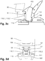
- Fig. 3d a view of a vertically aligned cross section running in the transverse direction of the ski through a heel support structure further Automatic heel unit in the holding configuration with the heel area of the ski boot.
- the automatic heel 1 belongs to a ski binding which, in addition to the automatic heel 1, includes an automatic front automatic device (not shown here) and in which a ski boot can be held.
- the ski boot can be held both in its toe area in the automatic front unit and with its heel area in the automatic heel unit 1 or, depending on the construction of the automatic front unit, also only with its toe area in the automatic front unit.
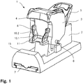
- the automatic heel unit 1 comprises a base plate 7 which serves as a base for fastening or mounting the automatic heel unit 1 on a ski.
- the automatic heel unit 1 further comprises a slide 2, a heel hold-down 3 with a heel hold-down structure 4 for holding down a ski boot, not shown here, held in the ski binding in the heel area of the ski boot, a heel support structure 6 for supporting the heel area of the ski boot held in the ski binding in a horizontal direction across the ski and an opening lever 5.
- the slide 2 is mounted on the base plate 7 so that it can be moved in the longitudinal direction of the ski and, viewed in the longitudinal direction of the ski, can be fixed in various positions on the base plate 7 in order to adapt the automatic heel unit 1 to ski boots of different sizes.
- the heel hold-down 3 is mounted on the slide 2, inter alia, so as to be pivotable about an axis 8 oriented horizontally in the transverse direction of the ski.
- a heel support 15 for supporting the heel area of the ski boot held in the ski binding is arranged on the slide 2 downwards to the ski.
- the heel hold-down device 3 In the entry-level configuration of the automatic heel unit 1, the heel hold-down device 3 is located as in FIG Figure 1 shown in an entry position. In addition, the opening lever 5 is in an entry position. In addition to this entry-level configuration, the automatic heel unit 1 also has a holding configuration. In this holding configuration of the automatic heel unit 1, the heel downholder 3 is in a holding position which differs from the entry position. In addition, the opening lever 5 is in a holding position. In the holding position, the heel hold-down 3 can hold the heel region 50 of a ski boot held in the ski binding, as in FIG Figure 2b shown in a lowered position with the heel hold-down structure 4 and support with the heel support structure 6 in a direction horizontally across the ski.
- the heel downholder 3 By moving the opening lever 5 from its holding position to its entry position and back, the heel downholder 3 can be moved from its holding position to its entry position and back relative to the slide 2. As a result, the automatic heel unit 1 can be adjusted from the holding configuration to the entry configuration and back.
- FIG. 1 the mounting of the heel hold-down 3 by the axis 8 is in a lower area of the heel hold-down 3.
- FIG. 1 the heel hold-down structure 4 is arranged in a front, upper region of the heel hold-down 3.
- the heel hold-down structure 4 has the shape of a forwardly protruding circular piece.
- the circle piece is aligned in a horizontal plane and forms a section of a circle, the center of which lies in front of the heel hold-down 3.
- the circular piece-shaped heel hold-down structure 4 rests on top of a rear-protruding sole area in the heel area of the ski boot.
- a round heel area of the ski boot is enclosed from the rear by the heel hold-down structure 4, partially at the side, reaching slightly forwards.
- the heel hold-down structure 4 does not, however, have to be in the shape of a circular piece. It can, for example, also be shaped in a straight line and oriented horizontally in the transverse direction of the ski and thus the heel area of the ski boot not laterally forward reach around. Regardless of its shape, the heel hold-down structure 4 holds down the heel area of the ski boot by pressing the sole area protruding backwards downwards. The heel hold-down structure 4 thus prevents the heel area of the ski boot from moving in a vertically upward direction.
- the heel hold-down 3 can be moved from its holding position into its entry position and back on an adjustment path relative to the slide 2 and relative to the base plate 7.
- the heel hold-down 3 can be moved vertically upwards in a first area of the adjustment path.
- the heel hold-down 3 is pretensioned towards its holding position by a spring, not shown here, which presses vertically downwards.
- the heel hold-down 3 can be pivoted backwards about the axis 8 along a second area of the adjustment path, so that the heel area 50 of the ski boot moves away from the Heel downholder 3 is released.
- This sequence of movements of the heel hold-down device 3 takes place both when the automatic heel unit 1 is adjusted from the holding configuration to the entry-level configuration and when the automatic heel unit 1 is enabled for safety release in the forward direction.
- the heel support structure 6 In a front lower area of the heel hold-down 3 there is the forward-cantilevered heel support structure 6.
- the heel support structure 6 is formed separately from the heel hold-down structure 4, but like the heel hold-down structure 4, it is arranged on the heel hold-down 3.
- the heel support structure 6 is designed to support the heel area of the ski boot only in one direction horizontally across the ski.
- the heel support structure 6 comprises two projections 10.1, 10.2 which protrude forward in the vertical direction. These projections 10.1, 10.2 form two projections in a horizontal cross-section running through the projections 10.1, 10.2 side-by-side, forward-facing legs.
- the heel support structure 6 further comprises a horizontal tread spur 11.
- the tread spur 11 can be pressed down with the ski boot.
- the heel hold-down 3 is first pivoted forward about the axis 8 along the third area of the adjustment path, in order then to be moved downwards along the second and first area of the adjustment path, whereby the heel hold-down structure 4, as already described, the rear-protruding sole area 52 in the heel area 50 of the ski boot presses down and thereby holds it down in a lowered position.
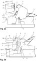
- Figure 2b shows a side view of a section running in the longitudinal direction of the ski through the automatic heel unit 1 in the holding configuration.
- the opening lever 5 is in its holding position and the heel hold-down 3 is in the holding position.
- a rear-facing stop element 9 arranged in an upper region of the heel hold-down 3 inside the heel hold-down 3 can be seen.
- the heel hold-down 3 is also movably supported with this stop element 9 on the slide 2.
- the stop element 9 is supported on an essentially vertically oriented, forward-facing surface of the slide 2. This surface forms an essentially vertical forced guidance for the stop element 9.
- the forward-facing surface of the carriage 2 limits movement of the stop element 9 only to the rear.
- the movement of the heel downholder 3 along the first area of the adjustment path is determined both by the guidance of the axis 8 in the elongated hole 12 and by the forced guidance of the stop element 9 on the forward-facing surface of the slide 2.
- the freedom of movement of the heel hold-down 3 is limited downwards and upwards by the guidance of the axis 8 around the elongated hole 12.
- the heel hold-down 3 can only be lifted upwards until the stop element 9 has just been lifted over the forward-facing surface of the carriage 2 and backwards along a surface of the carriage 2 that adjoins the upper edge of the surface and is inclined downwards to the rear can be moved down.
- the heel hold-down 3 is pivoted to the rear about the axis 8.
- the heel hold-down 3 is biased towards its holding position with an elastic element in the form of a spring, not shown here, in that the spring presses the axis 8 in the elongated hole 12 downwards. This means that in order to adjust the heel hold-down 3 from its holding position to its entry position, it must first be moved upwards against the force generated by the pretensioned spring along the first area of the adjustment path. Only when the stop element 9 has been raised above the forward-facing surface of the slide 2 can the heel hold-down 3 be pivoted backwards along the second area of the adjustment path.
- the heel area 50 in the holding configuration of the automatic heel unit 1 can also only be moved within an area relative to the heel hold-down structure 4, which results from the manufacturing tolerances of the heel support structure 6 and the heel hold-down structure 3.
- the projections 10.1, 10.2 thus block free movement of the heel region 50 of the in the Ski boots held in a ski binding in a horizontal direction across the ski.
- the ski boot can in any case be inserted between the projections 10.1, 10.2, whereby the function of the heel support structure 6 is ensured.
- FIGS Figures 3a - 3d show a further embodiment of an automatic heel unit 101 according to the invention, although the base plate of the automatic heel unit 101 serving as the base is not shown.
- This automatic heel unit 101 comprises essentially the same elements as that in FIGS Figures 1 , 2a and 2b 1.
- the automatic heel 101 comprises a support unit 113 which is separate from the heel downholder 103 and which comprises a support element on which the heel support structure 6 is formed.
- the support element of the support unit 113 is not firmly connected to the heel hold-down 103, but is movably mounted on the slide 102.
- the support element can be moved in the vertical direction along a straight adjustment path relative to the base, to the heel hold-down 103 and to the slide 102.
- the heel support structure 6 is arranged, as already mentioned, on the support element of the support unit 113. It has two elongated projections 110.1, 110.2, seen in the vertical direction, which protrude forward from the support element. These projections 110.1, 110.2 serve to support the heel area 50 of the ski boot held in the ski binding in the holding configuration of the automatic heel unit 101 in a direction horizontal across the ski.
- the support unit 113 also comprises an elastic element in the form of a spring 114.
- the support unit is pretensioned upwards away from the ski by this spring 114. Since the projections 110.1, 110.2 of the support unit 113, as in the embodiment of the previously described automatic heel unit 1, form sections running downwards in a vertical cross section running in the transverse direction of the ski through the projections 110.1, 110.2, they also serve for the heel area 50 of the ski boot downwards to the ski as a support.
- the heel area 50 of the ski boot rests on the projections 110.1, 110.2 and presses the support element against the bias of the spring 114 something down. Due to the spring 114, however, the support element is held upwards in its highest possible position. This ensures that the projections 110.1, 110.2 and thus the heel support structure 103 always interacts positively on both sides with the heel area 50 of the ski boot in a direction horizontal across the ski.
- the heel region 50 of the ski boot held in the holding configuration in the automatic heel device 101 is supported by the heel support 115 downwards towards the ski.
- the heel area 50 of the ski boot held in the holding configuration in the automatic heel unit can be supported by projections of the heel support structure downward towards the ski instead of a heel support. If, as in the two automatic heel units 1, 101 described above, the projections form sections running downwards towards one another in a vertical cross-section running in the transverse direction of the ski through the projections, the heel area 50 of the ski boot in the holding configuration can for example also be supported by these projections.
- the support element of the support unit 113 is in the entry position at an upper end of its vertical adjustment path.
- the axis 108 of the heel hold-down 103 is likewise located at an upper end of the elongated hole 112. As a result, the heel hold-down 103 is also in an upper position in the entry position.
- Figure 3c shows the automatic heel unit 101 in the holding configuration.
- the heel hold-down 103 is pivoted forward in its holding position and the axis 108 is located in the lower, first area of the adjustment path.
- the support element of the support unit 113 is also moved slightly downwards. Due to the bias of the spring 114, however, the support element of the support unit 113 is pressed from bottom to top against the counter structure 51 of the heel region 50 of the ski boot held in the ski binding. This ensures that the projections 110.1, 110.2 are always in contact with the recesses of the counter structure 51 from below and on both sides.
- the counter-structure 51 thereby interacts horizontally on both sides with the heel support structure 106 in a form-fitting manner during the entire time that the automatic heel 101 is in the holding configuration and the ski boot is held in the automatic heel 101.
- Figure 3c It can be seen that the heel region 50 of the ski boot is supported by the heel support 115 in a downward direction towards the ski.
- Figure 3d shows a view from the rear to the front of a vertically aligned section running in the transverse direction of the ski through the automatic heel unit 101 in the holding configuration with a ski boot held in the ski binding.
- the cut runs through a front area of the automatic heel unit 101 so that it runs through the forwardly protruding heel hold-down structure 104 and the projections 110.1, 110.2 of the heel support structure.
- the inner surface of the projections 110.1, 110.2 are at the same angle Vertical like the side surfaces of the structural element 53.
- both side surfaces of the structural element 53 are in contact with the inner surfaces of the projections 110.1, 110.2.
- the heel region 50 is held in a form-fitting manner on both sides in a horizontal direction transverse to the ski.
- the heel support 115 of the slide 102 supports the heel area 50 downwards towards the ski.
- the heel area 50 of the ski boot is thus supported via the structural element 53 of the counter structure 51 through the projections 110.1, 110.2 of the heel support structure 106 only in one direction horizontally across the ski and through the heel support 115 of the slide 102 down to the ski.
- the heel area 50 of the ski boot is held down via the rearwardly protruding sole area 52 in the heel area 50 of the ski boot by the circular piece-shaped heel hold-down structure 104.
- an automatic heel unit according to the invention can also be used for other ski bindings, such as, for example, downhill bindings.
- the heel hold-down with the heel hold-down structure and the slide can also be designed in one piece as one element.
- the heel support structure can be designed to be movable or fixed with respect to this one-piece element.
- the heel support structure is arranged directly on the slide.
- the heel support structure can not be arranged on the heel downholder, but rather form an independent element of the automatic heel unit.
- the heel support structure does not have to interact positively with the counter-structure of the heel area of the ski boot, as described above.
- the connection between the automatic heel unit and the ski boot can also be non-positive or positive and non-positive.
- the heel area of the ski boot does not have to have a counter structure.
- the heel support structure can also be designed in such a way that it interacts directly with a rear end of the heel region of the ski boot.
- the heel support structure is movable and pretensionable, an elastic element other than the spring 114 can also be used.
- an elastic element other than the spring 114 can also be used.
- the heel support structure is not pretensioned upwards, but in a different orientation.
- the described adjustment path of the support element of the support unit can also be oriented not in a vertical direction but, for example, in an inclined or horizontal direction.
- the adjustment path can also be curved.
- an automatic heel unit which is lightly constructed and yet allows the skier to drive in a sporty manner.
Claims (13)
- Talonnière (1, 101) pour une fixation de ski, notamment une fixation de ski de randonnée, comprenant une base (7) utilisée pour monter la talonnière (1, 101) sur un ski et un élément de maintien en position abaissée de talon (3, 103) avec une structure de maintien en position abaissée de talon (4, 104) permettant de maintenir en position abaissée une chaussure de ski maintenue dans la fixation de ski dans une zone de talon (50) de la chaussure de ski, l'élément de maintien en position abaissée de talon (3, 103) étant disposé de façon mobile par rapport à la base (7) et :a) la talonnière (1, 101) comportant une configuration de maintien dans laquelle l'élément de maintien en position abaissée de talon (3, 103) se trouve dans une position de maintien et dans laquelle la structure de maintien en position abaissée de talon (4, 104) peut interagir de telle sorte avec la zone de talon (50) de la chaussure de ski maintenue dans la fixation de ski que la zone de talon (50) de la chaussure de ski est maintenue dans une position abaissée ; etb) la talonnière (1, 101) comporte une configuration d'accès dans laquelle l'élément de maintien en position abaissée de talon (3, 103) se trouve dans une position d'accès et dans laquelle la zone de talon (50) de la chaussure de ski évolue librement par rapport à la structure de maintien en position abaissée de talon (4, 104) ;caractérisée en ce que la talonnière (1, 101) comprend une structure d'appui de talon (6, 106) réalisée de façon séparée de la structure de maintien en position abaissée de talon (4, 104) et ainsi de façon séparée dans l'espace de la structure de maintien en position abaissée de talon (4, 104) et saillant vers l'avant pour s'emboîter dans un évidement situé dans la zone de talon de la chaussure de ski maintenue dans la fixation de ski dans la configuration de maintien de la talonnière, pour appuyer la zone de talon (50) de la chaussure de ski maintenue dans la fixation de ski dans la configuration de maintien de la talonnière (1, 101) seulement dans une direction horizontale transversalement par rapport au ski ou seulement tant dans une direction horizontale transversalement par rapport au ski que dans une direction orientée vers le bas par rapport au ski, permettant ainsi à la structure d'appui de talon (6, 106) d'empêcher un mouvement libre de la zone de talon de la chaussure de ski dans une direction horizontale transversalement par rapport au ski et éventuellement en outre un mouvement libre dans une direction vers le bas par rapport au ski, de sorte que du fait de l'appui provoqué par la structure d'appui de talon (6, 106) dans la configuration de maintien de la talonnière (1, 101), la zone de talon de la chaussure de ski ne puisse pas être retirée en côté hors de la talonnière (1, 101), une section transversale s'étendant horizontalement à travers la structure d'appui de talon (6, 106) saillant vers l'avant comportant deux côtés (10.1, 10.2, 110.1, 110.2) disposés côte à côte et orientés vers l'avant.
- Talonnière (1, 101) selon la revendication 1, caractérisée en ce que pendant l'ensemble de la durée pendant laquelle la talonnière (1, 101) se trouve dans la configuration de maintien et pendant laquelle la structure de maintien en position abaissée de talon (4, 104) interagit de telle sorte avec la zone de talon (50) de la chaussure de ski maintenue dans la fixation de ski que la zone de talon (50) de la chaussure de ski est maintenue de façon abaissée dans la position abaissée, la structure d'appui de talon (6, 106) interagit par complémentarité de formes entièrement sur les deux côtés avec au moins une zone de jonction de la structure d'appui de talon (6, 106), avec une zone de jonction de la zone de talon (50) de la chaussure de ski.
- Talonnière (1, 101) selon la revendication 1 ou 2, caractérisée en ce que la structure d'appui de talon (6, 106) est réalisée pour maintenir, dans la configuration de maintien de la talonnière (1, 101), la zone de talon (50) de la chaussure de ski maintenue dans la fixation de ski dans une direction horizontale transversalement par rapport au ski, par rapport à la structure de maintien en position abaissée de talon (4, 104).
- Talonnière (1, 101) selon l'une quelconque des revendications 1 à 3, caractérisée en ce que la structure d'appui de talon (6, 106) est réalisée pour autoriser, dans la configuration de maintien de la talonnière (1, 101), un mouvement de la zone de talon (50) de la chaussure de ski maintenue dans la fixation de ski dans une direction horizontale transversalement par rapport au ski à l'intérieur d'une zone délimitée par rapport à la structure de maintien en position abaissée de talon (4, 104).
- Talonnière (1, 101) selon l'une quelconque des revendications 1 à 4, caractérisée en ce que la structure d'appui de talon (6, 106) est disposée sur l'élément de maintien en position abaissée de talon (3, 103) .
- Talonnière (1, 101) selon l'une quelconque des revendications 1 à 4, caractérisée en ce que la structure d'appui de talon (6, 106) est réalisée séparément de l'élément de maintien en position abaissée de talon (3, 103).
- Talonnière (1, 101) selon l'une quelconque des revendications 1 à 6, caractérisée en ce que la structure de maintien en position abaissée de talon (4, 104) est disposée fixement par rapport à la structure d'appui de talon (6, 106).
- Talonnière (1, 101) selon l'une quelconque des revendications 1 à 6, caractérisée en ce que la structure de maintien en position abaissée de talon (4, 104) est mobile par rapport à la structure d'appui de talon (6, 106).
- Talonnière (1, 101) selon l'une quelconque des revendications 1 à 8, caractérisée en ce que la talonnière comprend une unité d'appui formant la structure d'appui de talon (6, 106).
- Talonnière (1, 101) selon la revendication 9, caractérisée en ce que l'unité d'appui comprend au moins un élément d'appui (10.1, 10.2, 110.1, 110.2), l'au moins un élément d'appui (10.1, 10.2, 110.1, 110.2) formant la structure d'appui de talon.
- Talonnière (1, 101) selon la revendication 10, caractérisée en ce que l'au moins un élément d'appui (10.1, 10.2, 110.1, 110.2) est disposé de façon mobile le long d'une voie de déplacement par rapport à la base (7) .
- Talonnière (101) selon la revendication 11, caractérisée en ce que l'unité d'appui comprend un élément élastique (114) à travers lequel l'au moins un élément d'appui (10.1, 10.2, 110.1, 110.2) est précontraint vers le haut.
- Talonnière (1, 101) selon l'une quelconque des revendications 1 à 12, caractérisée en ce que la talonnière (1, 101) permet un déclenchement de sécurité.
Priority Applications (2)
| Application Number | Priority Date | Filing Date | Title |
|---|---|---|---|
| EP15194299.2A EP3167943B1 (fr) | 2015-11-12 | 2015-11-12 | Talonniere comprenant une structure d'appui de talon |
| US15/347,905 US9962595B2 (en) | 2015-11-12 | 2016-11-10 | Automatic heel unit with heel support structure |
Applications Claiming Priority (1)
| Application Number | Priority Date | Filing Date | Title |
|---|---|---|---|
| EP15194299.2A EP3167943B1 (fr) | 2015-11-12 | 2015-11-12 | Talonniere comprenant une structure d'appui de talon |
Publications (2)
| Publication Number | Publication Date |
|---|---|
| EP3167943A1 EP3167943A1 (fr) | 2017-05-17 |
| EP3167943B1 true EP3167943B1 (fr) | 2021-03-10 |
Family
ID=54542057
Family Applications (1)
| Application Number | Title | Priority Date | Filing Date |
|---|---|---|---|
| EP15194299.2A Active EP3167943B1 (fr) | 2015-11-12 | 2015-11-12 | Talonniere comprenant une structure d'appui de talon |
Country Status (2)
| Country | Link |
|---|---|
| US (1) | US9962595B2 (fr) |
| EP (1) | EP3167943B1 (fr) |
Families Citing this family (3)
| Publication number | Priority date | Publication date | Assignee | Title |
|---|---|---|---|---|
| DE102012206879B4 (de) | 2012-04-25 | 2021-12-23 | Marker Deutschland Gmbh | Leichtgewichtige Skibindung mit erhöhter Auslösesicherheit mit Stützeinrichtung |
| US10426221B2 (en) * | 2016-01-08 | 2019-10-01 | Nike, Inc. | Method and apparatus for dynamically altering a height of a sole assembly |
| EP3702005A1 (fr) | 2018-06-14 | 2020-09-02 | Fritschi AG - Swiss Bindings | Talonnière |
Family Cites Families (11)
| Publication number | Priority date | Publication date | Assignee | Title |
|---|---|---|---|---|
| FR2338060A1 (fr) * | 1976-01-16 | 1977-08-12 | Salomon & Fils F | Fixation de securite a dechaussage manuel |
| FR2560054B1 (fr) * | 1984-01-12 | 1986-12-12 | Salomon Sa | Chaussure de ski, fixation de ski et ensemble constitue d'une fixation de securite montee sur un ski et d'une chaussure de ski |
| US4971351A (en) * | 1987-01-27 | 1990-11-20 | Flick Arnold L | Ski binding device |
| AT402796B (de) | 1995-02-01 | 1997-08-25 | Fritschi Apparatebau | Schibindung |
| FR2739263B1 (fr) * | 1995-10-03 | 1998-06-26 | Salomon Sa | Ensemble forme par une paire de chaussures de glisse, notamment des chaussures de ski, et paire d'elements de retenue prevus pour retenir ces chaussures |
| DE102010043880B4 (de) * | 2010-11-12 | 2021-10-07 | Salewa Sport Ag | Ferseneinheit mit verschleißminderndern Ausgestaltuzng und Bügelelement für eine solche Ferseneinheit |
| DE102011082612A1 (de) * | 2011-09-13 | 2013-03-14 | SALEWA Sportgeräte GmbH | Ferseneinheit für eine Tourenbindung |
| DE102012206879B4 (de) | 2012-04-25 | 2021-12-23 | Marker Deutschland Gmbh | Leichtgewichtige Skibindung mit erhöhter Auslösesicherheit mit Stützeinrichtung |
| CH706664B1 (de) | 2012-06-15 | 2016-02-29 | Fritschi Ag – Swiss Bindings | Skibindung. |
| DE102013201725A1 (de) | 2013-02-01 | 2014-08-07 | Marker Deutschland Gmbh | Fersenhalter mit Verriegelungshebel |
| FR3026311A1 (fr) * | 2014-09-26 | 2016-04-01 | Salomon Sas | Talonniere de fixation d'une chaussure sur une planche de glisse |
-
2015
- 2015-11-12 EP EP15194299.2A patent/EP3167943B1/fr active Active
-
2016
- 2016-11-10 US US15/347,905 patent/US9962595B2/en active Active
Non-Patent Citations (1)
| Title |
|---|
| None * |
Also Published As
| Publication number | Publication date |
|---|---|
| EP3167943A1 (fr) | 2017-05-17 |
| US9962595B2 (en) | 2018-05-08 |
| US20170136341A1 (en) | 2017-05-18 |
Similar Documents
| Publication | Publication Date | Title |
|---|---|---|
| EP2608853B1 (fr) | Butée arrière de randonnee avec plage de glissement dynamique | |
| EP2705883B1 (fr) | Automate de talon pour une fixation de ski | |
| EP3566754B1 (fr) | Butée avant de fixation de ski | |
| EP2574379A2 (fr) | Automate avant | |
| DE202011110534U1 (de) | Tourenbindung | |
| DE202009019128U1 (de) | Zeheneinheit für Tourenskibindung | |
| EP3702005A1 (fr) | Talonnière | |
| EP3195906B1 (fr) | Talonniere ayant une configuration de marche | |
| DE102011082612A1 (de) | Ferseneinheit für eine Tourenbindung | |
| EP2813268A1 (fr) | Automate avant | |
| EP3167943B1 (fr) | Talonniere comprenant une structure d'appui de talon | |
| EP3345659B1 (fr) | Talonnière automatique pour une fixation de ski | |
| EP3053632B1 (fr) | Talonnière | |
| EP3120903B1 (fr) | Talonnière | |
| AT402795B (de) | Bindungseinheit zwischen einem schuh und einem sportgerät, insbesondere schibindung | |
| CH706664B1 (de) | Skibindung. | |
| EP3928842A1 (fr) | Unité avant pour une fixation de randonnée | |
| EP2821114B1 (fr) | Système de fixation de sécurité | |
| EP3848099A1 (fr) | Talon pourvu de cale de montée pour une fixation de randonnée | |
| EP3103525B1 (fr) | Talonnière | |
| CH705586A2 (de) | Frontautomat. | |
| EP2851108B1 (fr) | Mâchoire avant pour une fixation de ski | |
| EP3851174A1 (fr) | Butée avant pour une fixation de ski | |
| DE202013011994U1 (de) | Haltevorrichtung einer Skibindung mit getrennten Steighilfen | |
| EP3115089B1 (fr) | Talonnière |
Legal Events
| Date | Code | Title | Description |
|---|---|---|---|
| AK | Designated contracting states |
Kind code of ref document: A1 Designated state(s): AL AT BE BG CH CY CZ DE DK EE ES FI FR GB GR HR HU IE IS IT LI LT LU LV MC MK MT NL NO PL PT RO RS SE SI SK SM TR |
|
| AX | Request for extension of the european patent |
Extension state: BA ME |
|
| STAA | Information on the status of an ep patent application or granted ep patent |
Free format text: STATUS: REQUEST FOR EXAMINATION WAS MADE |
|
| 17P | Request for examination filed |
Effective date: 20170628 |
|
| RBV | Designated contracting states (corrected) |
Designated state(s): AL AT BE BG CH CY CZ DE DK EE ES FI FR GB GR HR HU IE IS IT LI LT LU LV MC MK MT NL NO PL PT RO RS SE SI SK SM TR |
|
| PUAI | Public reference made under article 153(3) epc to a published international application that has entered the european phase |
Free format text: ORIGINAL CODE: 0009012 |
|
| STAA | Information on the status of an ep patent application or granted ep patent |
Free format text: STATUS: EXAMINATION IS IN PROGRESS |
|
| 17Q | First examination report despatched |
Effective date: 20181204 |
|
| RIC1 | Information provided on ipc code assigned before grant |
Ipc: A43B 5/04 20060101ALN20200102BHEP Ipc: A63C 9/086 20120101ALI20200102BHEP Ipc: A63C 9/084 20120101ALI20200102BHEP Ipc: A63C 9/00 20120101ALN20200102BHEP Ipc: A63C 9/08 20120101AFI20200102BHEP |
|
| GRAP | Despatch of communication of intention to grant a patent |
Free format text: ORIGINAL CODE: EPIDOSNIGR1 |
|
| STAA | Information on the status of an ep patent application or granted ep patent |
Free format text: STATUS: GRANT OF PATENT IS INTENDED |
|
| INTG | Intention to grant announced |
Effective date: 20200211 |
|
| GRAJ | Information related to disapproval of communication of intention to grant by the applicant or resumption of examination proceedings by the epo deleted |
Free format text: ORIGINAL CODE: EPIDOSDIGR1 |
|
| STAA | Information on the status of an ep patent application or granted ep patent |
Free format text: STATUS: EXAMINATION IS IN PROGRESS |
|
| INTC | Intention to grant announced (deleted) | ||
| GRAP | Despatch of communication of intention to grant a patent |
Free format text: ORIGINAL CODE: EPIDOSNIGR1 |
|
| STAA | Information on the status of an ep patent application or granted ep patent |
Free format text: STATUS: GRANT OF PATENT IS INTENDED |
|
| RIC1 | Information provided on ipc code assigned before grant |
Ipc: A63C 9/086 20120101ALI20200507BHEP Ipc: A63C 9/084 20120101ALI20200507BHEP Ipc: A43B 5/04 20060101ALN20200507BHEP Ipc: A63C 9/00 20120101ALN20200507BHEP Ipc: A63C 9/08 20120101AFI20200507BHEP |
|
| INTG | Intention to grant announced |
Effective date: 20200605 |
|
| GRAJ | Information related to disapproval of communication of intention to grant by the applicant or resumption of examination proceedings by the epo deleted |
Free format text: ORIGINAL CODE: EPIDOSDIGR1 |
|
| STAA | Information on the status of an ep patent application or granted ep patent |
Free format text: STATUS: EXAMINATION IS IN PROGRESS |
|
| INTC | Intention to grant announced (deleted) | ||
| GRAP | Despatch of communication of intention to grant a patent |
Free format text: ORIGINAL CODE: EPIDOSNIGR1 |
|
| STAA | Information on the status of an ep patent application or granted ep patent |
Free format text: STATUS: GRANT OF PATENT IS INTENDED |
|
| RIC1 | Information provided on ipc code assigned before grant |
Ipc: A43B 5/04 20060101ALN20200831BHEP Ipc: A63C 9/086 20120101ALI20200831BHEP Ipc: A63C 9/08 20120101AFI20200831BHEP Ipc: A63C 9/084 20120101ALI20200831BHEP Ipc: A63C 9/00 20120101ALN20200831BHEP |
|
| INTG | Intention to grant announced |
Effective date: 20201006 |
|
| STAA | Information on the status of an ep patent application or granted ep patent |
Free format text: STATUS: GRANT OF PATENT IS INTENDED |
|
| GRAS | Grant fee paid |
Free format text: ORIGINAL CODE: EPIDOSNIGR3 |
|
| GRAA | (expected) grant |
Free format text: ORIGINAL CODE: 0009210 |
|
| STAA | Information on the status of an ep patent application or granted ep patent |
Free format text: STATUS: THE PATENT HAS BEEN GRANTED |
|
| AK | Designated contracting states |
Kind code of ref document: B1 Designated state(s): AL AT BE BG CH CY CZ DE DK EE ES FI FR GB GR HR HU IE IS IT LI LT LU LV MC MK MT NL NO PL PT RO RS SE SI SK SM TR |
|
| REG | Reference to a national code |
Ref country code: GB Ref legal event code: FG4D Free format text: NOT ENGLISH |
|
| REG | Reference to a national code |
Ref country code: AT Ref legal event code: REF Ref document number: 1369187 Country of ref document: AT Kind code of ref document: T Effective date: 20210315 Ref country code: CH Ref legal event code: EP |
|
| REG | Reference to a national code |
Ref country code: CH Ref legal event code: NV Representative=s name: KELLER SCHNEIDER PATENT- UND MARKENANWAELTE AG, CH Ref country code: IE Ref legal event code: FG4D Free format text: LANGUAGE OF EP DOCUMENT: GERMAN |
|
| REG | Reference to a national code |
Ref country code: DE Ref legal event code: R096 Ref document number: 502015014368 Country of ref document: DE |
|
| REG | Reference to a national code |
Ref country code: LT Ref legal event code: MG9D |
|
| PG25 | Lapsed in a contracting state [announced via postgrant information from national office to epo] |
Ref country code: LT Free format text: LAPSE BECAUSE OF FAILURE TO SUBMIT A TRANSLATION OF THE DESCRIPTION OR TO PAY THE FEE WITHIN THE PRESCRIBED TIME-LIMIT Effective date: 20210310 Ref country code: NO Free format text: LAPSE BECAUSE OF FAILURE TO SUBMIT A TRANSLATION OF THE DESCRIPTION OR TO PAY THE FEE WITHIN THE PRESCRIBED TIME-LIMIT Effective date: 20210610 Ref country code: BG Free format text: LAPSE BECAUSE OF FAILURE TO SUBMIT A TRANSLATION OF THE DESCRIPTION OR TO PAY THE FEE WITHIN THE PRESCRIBED TIME-LIMIT Effective date: 20210610 Ref country code: GR Free format text: LAPSE BECAUSE OF FAILURE TO SUBMIT A TRANSLATION OF THE DESCRIPTION OR TO PAY THE FEE WITHIN THE PRESCRIBED TIME-LIMIT Effective date: 20210611 Ref country code: HR Free format text: LAPSE BECAUSE OF FAILURE TO SUBMIT A TRANSLATION OF THE DESCRIPTION OR TO PAY THE FEE WITHIN THE PRESCRIBED TIME-LIMIT Effective date: 20210310 Ref country code: FI Free format text: LAPSE BECAUSE OF FAILURE TO SUBMIT A TRANSLATION OF THE DESCRIPTION OR TO PAY THE FEE WITHIN THE PRESCRIBED TIME-LIMIT Effective date: 20210310 |
|
| REG | Reference to a national code |
Ref country code: NL Ref legal event code: MP Effective date: 20210310 |
|
| PG25 | Lapsed in a contracting state [announced via postgrant information from national office to epo] |
Ref country code: SE Free format text: LAPSE BECAUSE OF FAILURE TO SUBMIT A TRANSLATION OF THE DESCRIPTION OR TO PAY THE FEE WITHIN THE PRESCRIBED TIME-LIMIT Effective date: 20210310 Ref country code: RS Free format text: LAPSE BECAUSE OF FAILURE TO SUBMIT A TRANSLATION OF THE DESCRIPTION OR TO PAY THE FEE WITHIN THE PRESCRIBED TIME-LIMIT Effective date: 20210310 Ref country code: LV Free format text: LAPSE BECAUSE OF FAILURE TO SUBMIT A TRANSLATION OF THE DESCRIPTION OR TO PAY THE FEE WITHIN THE PRESCRIBED TIME-LIMIT Effective date: 20210310 |
|
| PG25 | Lapsed in a contracting state [announced via postgrant information from national office to epo] |
Ref country code: NL Free format text: LAPSE BECAUSE OF FAILURE TO SUBMIT A TRANSLATION OF THE DESCRIPTION OR TO PAY THE FEE WITHIN THE PRESCRIBED TIME-LIMIT Effective date: 20210310 |
|
| PG25 | Lapsed in a contracting state [announced via postgrant information from national office to epo] |
Ref country code: CZ Free format text: LAPSE BECAUSE OF FAILURE TO SUBMIT A TRANSLATION OF THE DESCRIPTION OR TO PAY THE FEE WITHIN THE PRESCRIBED TIME-LIMIT Effective date: 20210310 Ref country code: EE Free format text: LAPSE BECAUSE OF FAILURE TO SUBMIT A TRANSLATION OF THE DESCRIPTION OR TO PAY THE FEE WITHIN THE PRESCRIBED TIME-LIMIT Effective date: 20210310 Ref country code: SM Free format text: LAPSE BECAUSE OF FAILURE TO SUBMIT A TRANSLATION OF THE DESCRIPTION OR TO PAY THE FEE WITHIN THE PRESCRIBED TIME-LIMIT Effective date: 20210310 |
|
| PG25 | Lapsed in a contracting state [announced via postgrant information from national office to epo] |
Ref country code: IS Free format text: LAPSE BECAUSE OF FAILURE TO SUBMIT A TRANSLATION OF THE DESCRIPTION OR TO PAY THE FEE WITHIN THE PRESCRIBED TIME-LIMIT Effective date: 20210710 Ref country code: ES Free format text: LAPSE BECAUSE OF FAILURE TO SUBMIT A TRANSLATION OF THE DESCRIPTION OR TO PAY THE FEE WITHIN THE PRESCRIBED TIME-LIMIT Effective date: 20210310 Ref country code: PT Free format text: LAPSE BECAUSE OF FAILURE TO SUBMIT A TRANSLATION OF THE DESCRIPTION OR TO PAY THE FEE WITHIN THE PRESCRIBED TIME-LIMIT Effective date: 20210712 Ref country code: PL Free format text: LAPSE BECAUSE OF FAILURE TO SUBMIT A TRANSLATION OF THE DESCRIPTION OR TO PAY THE FEE WITHIN THE PRESCRIBED TIME-LIMIT Effective date: 20210310 Ref country code: SK Free format text: LAPSE BECAUSE OF FAILURE TO SUBMIT A TRANSLATION OF THE DESCRIPTION OR TO PAY THE FEE WITHIN THE PRESCRIBED TIME-LIMIT Effective date: 20210310 Ref country code: RO Free format text: LAPSE BECAUSE OF FAILURE TO SUBMIT A TRANSLATION OF THE DESCRIPTION OR TO PAY THE FEE WITHIN THE PRESCRIBED TIME-LIMIT Effective date: 20210310 |
|
| REG | Reference to a national code |
Ref country code: DE Ref legal event code: R097 Ref document number: 502015014368 Country of ref document: DE |
|
| PLBE | No opposition filed within time limit |
Free format text: ORIGINAL CODE: 0009261 |
|
| STAA | Information on the status of an ep patent application or granted ep patent |
Free format text: STATUS: NO OPPOSITION FILED WITHIN TIME LIMIT |
|
| PG25 | Lapsed in a contracting state [announced via postgrant information from national office to epo] |
Ref country code: DK Free format text: LAPSE BECAUSE OF FAILURE TO SUBMIT A TRANSLATION OF THE DESCRIPTION OR TO PAY THE FEE WITHIN THE PRESCRIBED TIME-LIMIT Effective date: 20210310 Ref country code: AL Free format text: LAPSE BECAUSE OF FAILURE TO SUBMIT A TRANSLATION OF THE DESCRIPTION OR TO PAY THE FEE WITHIN THE PRESCRIBED TIME-LIMIT Effective date: 20210310 |
|
| 26N | No opposition filed |
Effective date: 20211213 |
|
| PG25 | Lapsed in a contracting state [announced via postgrant information from national office to epo] |
Ref country code: SI Free format text: LAPSE BECAUSE OF FAILURE TO SUBMIT A TRANSLATION OF THE DESCRIPTION OR TO PAY THE FEE WITHIN THE PRESCRIBED TIME-LIMIT Effective date: 20210310 |
|
| PG25 | Lapsed in a contracting state [announced via postgrant information from national office to epo] |
Ref country code: IS Free format text: LAPSE BECAUSE OF FAILURE TO SUBMIT A TRANSLATION OF THE DESCRIPTION OR TO PAY THE FEE WITHIN THE PRESCRIBED TIME-LIMIT Effective date: 20210710 |
|
| PG25 | Lapsed in a contracting state [announced via postgrant information from national office to epo] |
Ref country code: MC Free format text: LAPSE BECAUSE OF FAILURE TO SUBMIT A TRANSLATION OF THE DESCRIPTION OR TO PAY THE FEE WITHIN THE PRESCRIBED TIME-LIMIT Effective date: 20210310 |
|
| GBPC | Gb: european patent ceased through non-payment of renewal fee |
Effective date: 20211112 |
|
| PG25 | Lapsed in a contracting state [announced via postgrant information from national office to epo] |
Ref country code: LU Free format text: LAPSE BECAUSE OF NON-PAYMENT OF DUE FEES Effective date: 20211112 Ref country code: BE Free format text: LAPSE BECAUSE OF NON-PAYMENT OF DUE FEES Effective date: 20211130 |
|
| REG | Reference to a national code |
Ref country code: BE Ref legal event code: MM Effective date: 20211130 |
|
| PG25 | Lapsed in a contracting state [announced via postgrant information from national office to epo] |
Ref country code: IE Free format text: LAPSE BECAUSE OF NON-PAYMENT OF DUE FEES Effective date: 20211112 Ref country code: GB Free format text: LAPSE BECAUSE OF NON-PAYMENT OF DUE FEES Effective date: 20211112 |
|
| PG25 | Lapsed in a contracting state [announced via postgrant information from national office to epo] |
Ref country code: HU Free format text: LAPSE BECAUSE OF FAILURE TO SUBMIT A TRANSLATION OF THE DESCRIPTION OR TO PAY THE FEE WITHIN THE PRESCRIBED TIME-LIMIT; INVALID AB INITIO Effective date: 20151112 |
|
| PG25 | Lapsed in a contracting state [announced via postgrant information from national office to epo] |
Ref country code: CY Free format text: LAPSE BECAUSE OF FAILURE TO SUBMIT A TRANSLATION OF THE DESCRIPTION OR TO PAY THE FEE WITHIN THE PRESCRIBED TIME-LIMIT Effective date: 20210310 |
|
| PGFP | Annual fee paid to national office [announced via postgrant information from national office to epo] |
Ref country code: IT Payment date: 20231124 Year of fee payment: 9 Ref country code: FR Payment date: 20231120 Year of fee payment: 9 Ref country code: DE Payment date: 20231025 Year of fee payment: 9 Ref country code: CH Payment date: 20231202 Year of fee payment: 9 Ref country code: AT Payment date: 20231121 Year of fee payment: 9 |
|
| PG25 | Lapsed in a contracting state [announced via postgrant information from national office to epo] |
Ref country code: MK Free format text: LAPSE BECAUSE OF FAILURE TO SUBMIT A TRANSLATION OF THE DESCRIPTION OR TO PAY THE FEE WITHIN THE PRESCRIBED TIME-LIMIT Effective date: 20210310 |