EP3053632A1 - Talonnière - Google Patents
Talonnière Download PDFInfo
- Publication number
- EP3053632A1 EP3053632A1 EP15405009.0A EP15405009A EP3053632A1 EP 3053632 A1 EP3053632 A1 EP 3053632A1 EP 15405009 A EP15405009 A EP 15405009A EP 3053632 A1 EP3053632 A1 EP 3053632A1
- Authority
- EP
- European Patent Office
- Prior art keywords
- arms
- heel
- plane
- holding
- ski
- Prior art date
- Legal status (The legal status is an assumption and is not a legal conclusion. Google has not performed a legal analysis and makes no representation as to the accuracy of the status listed.)
- Granted
Links
- 230000027455 binding Effects 0.000 claims abstract description 25
- 238000009739 binding Methods 0.000 claims abstract description 25
- 230000008878 coupling Effects 0.000 claims description 43
- 238000010168 coupling process Methods 0.000 claims description 43
- 238000005859 coupling reaction Methods 0.000 claims description 43
- 230000013011 mating Effects 0.000 claims description 24
- 230000035939 shock Effects 0.000 claims description 5
- 239000002184 metal Substances 0.000 description 16
- 230000005540 biological transmission Effects 0.000 description 10
- 230000009194 climbing Effects 0.000 description 6
- 238000010276 construction Methods 0.000 description 6
- 239000013013 elastic material Substances 0.000 description 4
- 230000001174 ascending effect Effects 0.000 description 1
- 239000007844 bleaching agent Substances 0.000 description 1
- 238000010586 diagram Methods 0.000 description 1
- 230000009365 direct transmission Effects 0.000 description 1
- 238000006073 displacement reaction Methods 0.000 description 1
- 238000009826 distribution Methods 0.000 description 1
- 230000014759 maintenance of location Effects 0.000 description 1
- 238000000926 separation method Methods 0.000 description 1
- 239000007787 solid Substances 0.000 description 1
Images


Classifications
-
- A—HUMAN NECESSITIES
- A63—SPORTS; GAMES; AMUSEMENTS
- A63C—SKATES; SKIS; ROLLER SKATES; DESIGN OR LAYOUT OF COURTS, RINKS OR THE LIKE
- A63C9/00—Ski bindings
- A63C9/08—Ski bindings yieldable or self-releasing in the event of an accident, i.e. safety bindings
- A63C9/084—Ski bindings yieldable or self-releasing in the event of an accident, i.e. safety bindings with heel hold-downs, e.g. swingable
- A63C9/0846—Details of the release or step-in mechanism
-
- A—HUMAN NECESSITIES
- A63—SPORTS; GAMES; AMUSEMENTS
- A63C—SKATES; SKIS; ROLLER SKATES; DESIGN OR LAYOUT OF COURTS, RINKS OR THE LIKE
- A63C9/00—Ski bindings
- A63C9/08—Ski bindings yieldable or self-releasing in the event of an accident, i.e. safety bindings
- A63C9/0807—Ski bindings yieldable or self-releasing in the event of an accident, i.e. safety bindings for both towing and downhill skiing
-
- A—HUMAN NECESSITIES
- A63—SPORTS; GAMES; AMUSEMENTS
- A63C—SKATES; SKIS; ROLLER SKATES; DESIGN OR LAYOUT OF COURTS, RINKS OR THE LIKE
- A63C9/00—Ski bindings
- A63C9/08—Ski bindings yieldable or self-releasing in the event of an accident, i.e. safety bindings
- A63C9/086—Ski bindings yieldable or self-releasing in the event of an accident, i.e. safety bindings using parts which are fixed on the shoe of the user and are releasable from the ski binding
Definitions
- the invention relates to a heel automaton for a ski binding, in particular a touring ski binding.
- the inventive automatic heel comprises a heel holder with a holding device for holding a ski boot in the region of a heel of the ski boot.
- the holding device comprises two arms, which are arranged in a first plane, wherein on each of the two arms a holding means for holding the ski boot in the region of the heel of the ski boot is arranged.
- the two arms are movable in the first plane relative to each other, whereby a distance between the two holding means is changeable.
- the holding device comprises a first stub element, which is movable relative to the two arms and relative to the first plane, and a prestressed first elastic element, by the bias of which a first force can be generated on the first stub element.
- ski bindings are subdivided into piste bindings, which are used only for downhill skiing and downhill skiing, and touring bindings, which are also used for walking on skis, in particular for ascending with the help of climbing skins attached to the skis. While the former only have to ensure a reliable fixation of the ski boot on the ski in a so-called downhill position, the latter must be brought to ascend additionally from the downhill to a climbing position in which the ski boot is pivotable about an axis in Skiquerides pivotally in the heel area of the ski to allow for joint movement between the ski boot and the ski to go.
- Touring ski bindings can be divided into two types.
- the first type comprises a ski boot carrier pivotable relative to the ski, on which the ski boot is held by binding jaws.
- a representative member of this type of touring ski bindings is, for example, in EP 0 754 079 B1 (Fritschi AG).
- the second type relies on ski boots with a stiff sole.
- the ski boot is pivotally mounted in his toe area in a skim-mounted front automat.
- the automatic heel unit is also fixed in a distance from the front automat on the ski adapted to a ski boot sole length and locks the ski boot in the heel area in the downhill position.
- ski boots In the ascent position, the heel of the ski boot is released from the heel unit, so that the ski boot can be lifted off the ski and swiveled around the storage on the front automat.
- this type of binding suitable ski boots this typically have in the toe area two lateral recesses for pivotal mounting in the front vending machine. Next, they have in the heel area to the rear open recesses into which holding means of the heel unit can intervene.
- These holding means may be, for example, two forward facing pins.
- ski boots are commercially available, which have in their heel area recesses for receiving two forward facing pins as holding means.
- the distance in which the heel counter must be mounted on the ski from the front automatic machine is determined by the length of the sole of the ski boot to be held in the context of an adjustability of the heel piece.
- ski longitudinal direction means along the orientation of the longitudinal axis of the ski.
- skiparallel means aligned for an elongate object along the longitudinal axis of the ski.
- ski-parallel means aligned parallel to the sliding surface of the ski.
- ski direction means a direction transverse to the ski longitudinal direction, which, however, need not be oriented exactly at right angles to the longitudinal axis of the ski. Their orientation may also be slightly different from a right angle.
- ski center means a center of the ski in the ski direction
- ski manifest does not mean that it can move in relation to the ski.
- ski refers to the reference system of (fictitious) skis.
- front, “rear”, “top”, “bottom” and “side” refer to “front”, “rear”, “top”, “bottom” and “side” of the ski.
- horizontal and vertical refer to the ski, with “horizontal” lying in a ski-parallel plane and “vertical” oriented perpendicular to this plane.
- AT 402 020 B (Barthel ) such a heel machine. It comprises a housing which is pivotable on a mounting plate about an invisible vertical axis against the force of a spring mounted in the housing. In the upper part of the housing two arms are arranged. In the rear region of these two arms vertical axes are arranged, about which the two arms are pivotally mounted. As a result, the two arms are pivotable in a horizontal plane. The front ends of the two arms cantilever forward relative to the housing. These front ends of the two arms form forward-pointing pins, which serve as holding means by being in Recesses in the heel of a ski boot can intervene to hold the ski boot.
- the arms carry wedge-shaped oblique surfaces which are perpendicular to the horizontal pivoting plane of the arms and lead laterally apart towards the pins.
- a U-shaped bracket, which serves as a stub element is pressed by two springs arranged between the arms from back to front against the inclined surfaces of the arms. As a result, the two arms are pressed towards each other.
- a stop located between the arms prevents the two arms from being pivoted closer than to a minimum distance apart. Therefore, the two pins are held to each other due to the force generated by the springs on the bracket at a predetermined distance.
- the heel automat according to AT 402 020 B (Barthel ) enables a safety release in the forward direction.
- the two pins are forced apart against the force of the springs due to the shape of the heel of the ski boot until the heel of the ski boot has detached upwards from the heel counter.
- the heel box picks up energy.
- the total energy absorbed by the heel unit depends on the path traveled by the pins to release and on the spring force which has to be overcome during the travel of the pins. Due to the shape of the heel of the ski boot is the path, which is covered by the pins to the release set.
- the spring force which must be overcome during the path of the pins, can be adjusted in the heel counter. This allows the heel counter to adjust the energy that can be absorbed by the heel counter until a safety trip in the forward direction occurs.
- This setting is also referred to as setting the tripping force, setting the tripping value or somewhat imprecise simply as setting the safety release.
- the WO 2012/024809 A1 discloses an automatic heel unit, which belongs to the technical field mentioned above.
- This automatic heel also includes two forward facing pins which serve as a means of retention and can engage recesses in the heel of a ski boot to hold the ski boot.
- the pins in the heel unit according to the AT 402 020 B are the pins in the heel unit according to the WO 2012/024809 A1 (Fritschi AG), however, arranged on vertically oriented arms. These arms are mounted in a vertical, transversely aligned to the longitudinal direction of the ski pivotally mounted on the housing of the heel holder. They have at their lower ends to back paragraphs.
- a spring is arranged, which presses a piston parallel to the arms down against the shoulders arranged on the arms. Characterized the upper ends of the arms are pressed against the arranged between the arms front wall of the housing of the heel holder. As a result, the two arms are held in a position in which the pins are at a predetermined distance from each other.
- the heel automat according to WO 2012/024809 A1 also enables a safety release in the forward direction. Again, the safety release is set by adjusting the spring force.
- Both the AT 402 020 B (Barthel ) as well as the WO 2012/024809 A1 (Fritschi AG) describe the respective heel piece as belonging to a touring ski binding, which belongs to the above-mentioned second type.
- these heel machines can also be used on touring ski bindings of the above-mentioned first type and in piste bindings.
- these heel machines have the disadvantage that they allow a setting of the safety release only within a limited adjustment range.
- the reason for this is on the one hand the limited way, which is covered by the pins, until it comes to a release.
- the limited space for the spring is one reason. The latter means that no stronger spring can be installed without significantly increasing the volume of the heel counter. Accordingly, the heel machines can not be adjusted so that they can absorb high-energy impacts on the ski, the ski boot and the ski binding in a particularly sporty driving style, without causing an unintentional safety release.
- the object of the invention is to provide a the aforementioned technical field associated automatic heel, which allows a setting of the safety release for a particularly sporty driving in a compact design of the heel unit.
- the first push member is movable in a second plane oriented substantially perpendicular to the first plane, and the first force, which is aligned in the second plane, can be pressed against the two arms to hold the two arms in a holding position which are the two holding means at a predetermined distance from each other.
- "in a second plane aligned substantially at right angles to the first plane” means that the smallest intersecting angle measured between the first plane and the second plane is greater than 45 °.
- this smallest intersection angle measured between the two planes is greater than 70 °, particularly preferably greater than 85 ° or approximately 90 °.
- the heel machine is mounted exactly on the ski.
- the heel holder can be mounted directly on the ski.
- the heel holder can be mounted indirectly via one or more further elements on a ski.
- the automatic heel unit can have a base element which can be mounted on the ski and on which the heel holder is fastened or on which the heel holder is movably mounted.
- the heel holder is precisely shaped.
- the holding device forms the entire heel holder or whether the holding device forms only a part of the heel holder.
- the holding device is an integral part of the heel holder or whether the holding device forms a separable from the rest of the heel holder unit.
- the two arms arranged in the first plane may be two physically separate elongated structures. They can each be in one piece or off be composed of several elements. But there is also the possibility that the two arms are two elongated structures that are physically connected to each other. In this case, the two arms and their connection can be made in one piece and formed, for example, by the two free ends of a bent metal bar to a bracket. The connection can also be made as a separate element, which is attached to the two arms and thereby physically connects the two arms together. Regardless of the type of connection, it does not matter whether the arms are themselves integral or made up of several elements.
- the shape of the first elastic element is irrelevant to the solution of the problem.
- the first elastic member may be formed by a coil spring, a leaf spring, or any other spring. But it is also possible that the first elastic member is formed of an elastic material without having the shape of a spring.
- the first elastic element may be a block of elastic material. Regardless of the shape of the first elastic element, the first elastic element may also have a plurality of individual parts and, for example, comprise a plurality of parallel or serially arranged springs.
- the first stub element can be pressed against the two arms by the first force generated by the prestressing of the first elastic element and oriented in the second plane. Since the second plane is oriented substantially perpendicular to the first plane while the two arms are arranged in the first plane, the first force exerted by the first pushing element thus acts at an angle to align the two arms with the two arms. Therefore, the first elastic member can be easily disposed outside the first plane, so that the space occupied by the first elastic member is separated from the space occupied by the two movable arms.
- the solution according to the invention has the advantage that it allows the use of a larger and stronger elastic element, without the automatic heel unit having to be constructed larger.
- the automatic heel unit allows a safety release in the forward direction. This has the advantage that safety is increased for the skier. Alternatively, there is also the possibility that the automatic heel unit does not allow safety release in the forward direction.
- the two holding means are each formed by a pin, in particular by a forward facing pin.
- the holding means may also be designed differently. So they can, for example, each form a half of a jaw, which surrounds the heel of the ski boot as in the case of known Pistenitatien rear top and side.
- the two arms are movable away from their holding position against the first force generated by the prestressed first elastic element.
- the two holding means are preferably movable away from one another by the two arms are moved away from its holding position against the first force generated by the prestressed first elastic element.
- the holding means can be moved apart, for example, in a safety release in the forward direction against the first force to release the ski boot. This has the advantage that the ski boot in a safety release in the forward direction can be released in a simple manner.
- the two holding means are movable relative to each other by the two arms are moved away from its holding position against the first force generated by the prestressed first elastic element.
- the ski boot can be released in a safety release in the forward direction in a simple manner.
- the holding means are arranged in the region of a first end of the arms. This has the advantage that the largest part of the arms can be spatially separated from the holding means, so that a heel machine construction with stable mounting of the two arms is made possible, which allows at the same time with the holding means a trouble holding the ski boot.
- the holding means are not arranged in the region of the first end of the arms.
- the holding means may be arranged on the arms in the region of the middle of the arms or in the region of one third or quarter of the arm length from the first end of the arms.
- the two arms are preferably pivotable with their first ends about a pivoting range, which lies in the region of the second, the first ends of the two arms opposite ends of the two arms ,
- the two arms can be pivotally mounted in the pivoting area about a common axis or each about separate axes, have elastic regions or be connected to each other by an elastic connection.
- the pivotability of the two arms with their first ends about the pivoting area in the region of the second ends of the two arms has the advantage that the first ends of the arms opposite the second end of the arms cover the greatest possible distance during a pivotal movement of the arms.
- the holding means are arranged at the first ends of the two arms, this can be used so that the holding means cover the greatest possible distance during a pivoting movement of the two arms. If the first stub element cooperates with the two arms in the region of the first ends of the two arms, optimum transmission of force between the arms and the first stub element can be achieved due to the maximum distance traveled by the arms during a pivoting movement.
- the two arms are pivotable with their first ends about a pivoting range of the two arms, which between the first ends and the second ends of the two arms is arranged.
- the two arms can be pivotally mounted in the pivoting area about a common axis or each about separate axes, have elastic regions or be connected to each other by an elastic connection.
- the two arms are not pivotally mounted, but displaceable. They can maintain their orientation during a shift or additionally be pivotable about a possibly moving, geometric or physical axis.
- the first push member and the two arms are shaped and cooperate such that the two arms are always biased to the holding position by the first force with which the first push member is pushable against the two arms Holding means are at a predetermined distance from each other.
- This has the advantage that the two holding means are always biased by the first force generated by the first elastic element to a holding position, which is why even the smallest movement of the holding means from its holding position takes place against the first force. Therefore, a low energy impact on the ski, ski binding, or ski boot causes only a slight movement of the retaining means against the first force, and thus only a slight movement of the ski boot relative to the ski. Accordingly, the ride comfort for the skier is increased.
- the push element and the two arms are shaped and cooperate in such a way that the two arms are biased into the holding position by the first force, with which the first push element can be pressed against the two arms two arms are moved away from the holding position.
- the first mating member preferably has a first positioning structure for cooperation with the two arms, wherein the first positioning structure in such a way is shaped and cooperates with the two arms such that the first stub member is disposed in a first position when the two arms are in the holding position, and the farther the two arms are moved away from the holding position, the farther from the first Position is moved away in a direction which is opposite to the direction of action of the force acting on the first push member first force.
- the first positioning structure may include one or more surfaces that are oriented obliquely to the first plane and with which the first interference element contacts one or both of the two arms.
- the one or more surfaces of the first positioning structure may be flat or curved.
- the first positioning structure is shaped differently and has no surface which is aligned obliquely to the first plane.
- the first stub element has no such first positioning structure.
- the holding device comprises a second push element, which is arranged on a side of the two arms opposite the first push element and is movable relative to the two arms and relative to the first plane.
- a second push element which is arranged on a side of the two arms opposite the first push element and is movable relative to the two arms and relative to the first plane.
- the holding device does not comprise such a second stub element or that any existing second stub element is arranged differently relative to the two arms or other relative to the two arms and movable relative to the first plane.
- the holding device comprises a second stub element, which is arranged on a side of the two arms opposite the first stub element and relative to the two Poor and movable relative to the first plane
- the second mating element is advantageously movable in the second plane.
- the second mating member may not be movable in the second plane.
- Such an alternative has the advantage that a simpler construction of the heel counter is made possible.
- the second push member is movable in the second plane
- the second push member advantageously has a second positioning structure for co-operating with the two arms, the second positioning structure being shaped and cooperating with the two arms such that the second push member is in a second Position is arranged when the two arms are in the holding position, and, the farther the two arms are moved away from the holding position, the further moved away from the second position.
- the second positioning structure may include one or more surfaces that are oriented obliquely to the first plane and with which the second interference element contacts one or both of the two arms.
- the one or more surfaces of the second positioning structure may be flat or curved.
- the second positioning structure is shaped differently and has no surface which is aligned obliquely to the first plane.
- the second mating element has no such second positioning structure.
- the second mating element can be pressed against the two arms due to the bias of the first elastic element with a second force aligned in the second plane.
- this second force with which the second push member is pressed against the two arms preferably opposite to the first force with which the first push member against the two arms can be pressed.
- the holding device comprises a second elastic element, by the bias of which a third force aligned in the second plane can be generated on the second pushing element, with which the second pushing element can be pressed against the two arms, in order to urge the two arms in the second Hold holding position in which the two holding means are at a predetermined distance from each other.
- this third force with which the second push member is pressed against the two arms, preferably opposite to the first force with which the first push member against the two arms can be pressed.
- the shape of the second elastic element is irrelevant.
- the second elastic member may be formed by a coil spring, a leaf spring or any other spring.
- the second elastic member is formed of an elastic material without having the shape of a spring.
- the second elastic element may be a block made of an elastic material.
- the second elastic element may also have a plurality of individual parts and, for example, comprise a plurality of parallel or serially arranged springs.
- Both this first variant and this second variant have the advantage that the first and the second mating element are pressed against two opposing sides against the two arms arranged between the mating elements, whereby a better transmission of force to the two arms is achieved to hold two arms in the holding position.
- the second stub element can not be pressed by a second force against the two arms.
- the holding device comprises a coupling element, by which the first and the second mating element are coupled together. Regardless of whether this coupling element is formed in one piece or several pieces, the coupling element has the advantage that a power transmission from the male elements is improved on the two arms.
- the holding device does not comprise a coupling element, by which the first and the second mating element are coupled together.
- the holding device comprises a coupling element
- the first and the second pushing element are preferably coupled together by the coupling element such that the first and second pushing elements can be pressed against the two arms from opposite sides of the two arms to form the two arms in the Hold position.
- the first and the second push elements are coupled to one another in such a way by the coupling element that the first and the second force or the first and the third force are equally strong, so that the first and the second push element are substantially equally strong from opposite sides of the two arms are pressed against the two arms to hold the two arms in the holding position.
- the first and the second push elements are coupled to one another in such a way by the coupling element that the first and the second force or the first and the third force are of different strength, so that the first and the second push element differ in magnitude from one another Sides of the two arms are pressed against the two arms to hold the two arms in the holding position.
- first and second coupling elements may also be coupled to one another differently by the coupling element.
- the coupling element is preferably aligned in the second plane. If, in this case, the coupling element has a planar extension, without having an elongated extension, then "oriented in the second plane" means that the planar extension of the coupling element is aligned in the second plane. In contrast, if the coupling element is elongated and thus has a longitudinal axis, then “aligned in the second plane” means that the longitudinal axis of the coupling element is aligned in the second plane.
- the elongate coupling element may also have a planar extension.
- this areal extent may also be oriented differently than in the second plane, as long as the longitudinal axis of the coupling element is aligned in the second plane.
- the alignment of the coupling element in the second plane has the advantage that the coupling element can optimally transmit a force aligned in the second plane from the first stub element to the second stub element or vice versa and thus optimally with the first and second stub elements a power transmitting coupling can couple with each other.
- the coupling element is movable in the second plane relative to the two arms and relative to the first plane.
- This has the advantage that the elements of the holding device can easily be adapted to the positioning of the two arms and external forces acting on the heel holder so that any mutual tilting or possible tilting of the elements of the holding device and of the remaining heel counter is prevented .
- the coupling element which can be moved relative to the two arms and relative to the first plane has the advantage that unilateral force distributions are possible between the first and the second via the coupling element Stossselement be compensated in a simple manner can be so pressed that the first and the second Stosselement with an equally strong force against the two arms.
- the coupling element is not movable in the second plane relative to the two arms.
- At least one of the first and second push members is movable in the second plane relative to the coupling member. This has the advantage that the distance between the first and the second mating element via the coupling of the first and the second mating element by the coupling element can be adapted dynamically to the positioning of the two arms in a simple manner.
- neither the first nor the second push element can be movable in the second plane relative to the coupling element.
- the two arms as well as the first and second stub elements are movable relative to a housing of the heel holder.
- This has the advantage that forces occurring during skiing, which act from the ski boot on the holding means and thus on the two arms, can be better absorbed.
- This advantage is also achieved if, in addition, the first elastic element and the possibly existing second elastic element are movable relative to the housing of the heel holder. In the same way, this advantage is achieved even if the possibly existing coupling element is movable relative to the housing of the heel holder.
- the heel holder has no housing or that of any existing coupling element, possibly existing second elastic element, first elastic element, first stub element, second stub element and one of the two arms one or more elements not relative to the housing of the Heel holders are movable.
- the latter may for example be the case when one or more of these elements are integral components of the housing of the heel holder.
- the first level is horizontal and the second level is vertically aligned.
- the first level is vertical and the second level is aligned horizontally.
- the first stub element being horizontally movable and the first force with which the first stub element can be pressed against the two arms being aligned horizontally.
- This has the advantage of facilitating a construction of the heel counter where the heel box has enough room for a strong first elastic member to generate a strong first force, and in which the first elastic member is oriented horizontally, so that it directs the first force and can transfer to the first stub element without a complicated transfer device.
- first level and the second level are oriented differently.
- the holding device preferably comprises an adjustment by which the bias of the first elastic member is adjustable, by adjusting the bias of the first elastic member, the energy of a shock can be adjusted, which is one of the heel piece enabled safety release in the forward direction is at least required.
- the holding device also has a second elastic element, the biasing of the second elastic element is preferably adjustable by means of the adjusting device, wherein the energy of a shock can be adjusted by adjusting the bias of the first and second elastic elements by means of the adjusting device is at least necessary for a safety release enabled by the heel unit in the forward direction. But there is also the possibility that only the bias of the first elastic element is adjustable by the adjustment, while the bias of the second elastic member is fixed.
- the adjustability of Bias of the first elastic element by the adjustment means has the advantage that the safety release in the forward direction is adjustable.
- the holding device does not comprise such an adjusting device.
- FIG. 1 shows a representation of a cross section through an inventive heel counter 1.
- This cross section is vertically aligned and extends in the middle of the heel unit 1 in the ski longitudinal direction.
- 1 is at the heel counter, while 1 is at the back in the heel counter.
- Above and below in the illustration also correspond to the heel machine 1 above and below.
- the in the FIG. 1 Lines denoted by reference numerals A, B and C correspond to the positions of the cross sections taken in the FIGS. 4, 3 and 2 are shown.
- the automatic heel unit 1 comprises a heel holder 2 with a housing 3.
- the automatic heel unit 1 in addition to the heel holder 2 may also comprise some other elements which are less relevant to the present invention and are therefore not shown in the figures.
- the automatic heel unit 1 may comprise a base element, not shown here, with which the automatic heel unit 1 can be fastened on a ski.
- the heel holder 2 may be mounted on this base element in a known manner. Examples of how the base element can be shaped and how the heel holder 2 can be mounted on the base element are in the documents already described above AT 402 020 B (Barthel ) and WO 2012/024809 A1 (Fritschi AG) explained in more detail. Other examples are but also for example in the EP 2 705 883 A1 (Fritschi AG).
- the automatic heel unit 1 is constructed without a base element by the heel holder 2 can be fastened directly on the ski.
- the automatic heel unit 1 may also include an actuating lever, not shown here, with which the heel holder 2 is displaceable in the longitudinal direction relative to the base element or with which the heel holder 2 relative to the base member is pivotable about a vertically oriented axis. Designs for such an actuating lever are also known from the cited documents.
- the automatic heel unit 1 may also include one or more climbing aids, not shown here. Such climbing aids are also known from the cited documents.
- the housing 3 of the heel holder 2 seen in the ski longitudinal direction can be divided into three areas.
- the housing 2 has only a small height. This area serves to support the ski boot down.
- this area offers space for recording the footboard of a not shown here, but from the WO 2012/024809 A1 (Fritschi AG) known ski brake.
- the housing 3 In the central region of the housing 3, the housing 3 has its greatest height. In this area, the housing 3 defines a cavity to the outside, in which most of the elements of a holding device 4 of the heel unit 1 are arranged.
- the housing 3 has an average height, which lies between the height of the front region and the height of the central region.
- the holding device 4 comprises a bracket 5 bent from a metal rod.
- This bracket 5 is arranged in the upper region of the middle region of the housing 2 and aligned horizontally. He is thus arranged in a horizontally oriented, first level.
- a plan view of a cross section through the heel unit 1 along this first plane is shown in FIG FIG. 2 shown. As a result, some of the details described below are in the FIG. 2 better than in the FIG. 1 to recognize.
- the course of the Cross section or the first level is in the FIG. 1 marked by the line designated by the reference C.
- the curvature of the bracket 5 extend back beyond the housing 2, while the two free ends of the bracket 5 extend through the central region of the housing 2 and extend forward beyond the housing 2.
- the free ends of the bracket 5 form two arms 6.1, 6.2, which are aligned in the horizontal, first plane and are movable in this first plane by the bracket 5 is bent slightly apart or together in the region of its curvature.
- the front, first ends of the two arms 6.1, 6.2 are moved apart.
- these first ends of the two arms 6.1, 6.2 extend forward over the middle region of the housing 2. They form two forward facing pins 7.1, 7.2, which as described above can engage in the heel of a ski boot to be held to hold the ski boot.
- the two arms 6.1, 6.2 extend from the back to the front through the cavity in the middle region of the housing 3.
- a first stub element 8 is arranged below the two arms 6.1, 6.2, while above the two arms 6.1, 6.2, a second stub element 9 is arranged.
- Both mating elements 8, 9 have an elongated shape and are aligned with their longitudinal axis horizontally in the cross-machine direction.
- a spindle 10 extends vertically through both push elements 8, 9.
- the spindle 10 and the two push elements 8, 9 are in a vertical, running in the ski direction, second plane aligned. Both the spindle 10 and the two mating elements 8, 9 are also movable in this second plane.
- the spindle 10 comprises at its upper end a head with which it is supported against the upper edge of the second push member 9. As a result, the spindle 10 is raised when the second push member 9 is lifted. In the same way, however, the second pusher element 9 is also pulled down when the spindle 10 is moved downwards. After the second stub element 9, the spindle 10 extends downwardly through an opening in the first stub element 8. A diameter of this opening in the first Stem element 8 is slightly larger than a diameter of the spindle 10, so that the first stub element 8 can be moved along the spindle 10 relative to the spindle 10. This makes it possible for the first and second push elements 8, 9 to be moved apart or toward one another in the second plane. Thus, both the two push elements 8, 9 and the spindle 10 are movable relative to the two arms 6.1, 6.2 and relative to the first plane.
- the spindle 10 continues vertically downwards to its lower end, which is screwed into a threaded nut 11.
- This threaded nut 11 is embedded in a piece of sheet metal 12 which is mounted displaceably in the vertical direction in the housing 3 of the heel holder 2.
- the sheet metal piece 12 prevents the threaded nut 11 from rotating, but allows a displacement of the threaded nut 11 together with the sheet metal piece 12 within the housing 3 in the vertical direction. Since the head of the spindle 10 is accessible from above, the spindle 10 can be rotated about a vertical axis.
- the threaded nut 11 which is prevented by the sheet metal piece 12 at a co-rotation, along with the sheet metal piece 12 along the spindle 10 depending on the direction of rotation moves up or down. Since a wound around the spindle 10 coil spring 13 is clamped between the threaded nut 11 and the first Stosselement 8, thus, a bias of the coil spring 13 can be adjusted by a rotation of the spindle 10. In this case, the bias of the coil spring 13 due to the position of the sheet metal piece 12 in a window 14 on the back of the central region of the housing 3 can be read.
- the first stub element 8 is pressed with a aligned in the second plane first force from below upwards against the two arms 6.1, 6.2.
- the lower end of the coil spring 13 presses with a force which is equal to the first force, the threaded nut 11 down.
- the spindle 10 is pressed down with the same force. Due to the head of the spindle 10, which is supported against the upper edge of the second push member 9, therefore, the second push member 9 is pressed with this force down.
- the second push member 9 is aligned with a second plane aligned in the second plane, generated by the bias of the coil spring 3, second force down against the two arms 6.1, 6.2 pressed.
- the spindle 10 couples the first and second mating elements 8, 9 together and may also be referred to as a coupling element.
- the spindle 10 together with the threaded nut 11 and the sheet metal piece 12 may also be referred to as an adjusting device, which allows the adjustment of the bias of the spring.
- FIG. 3 shows a representation of a viewed from the front cross-section along the second plane through the inventive heel counter 1. The course of this cross section is in the FIG. 1 marked by the line with the reference symbol B.
- FIG. 3 shown cross section extends in the vertical direction along the spindle 13 and along the two die elements 8, 9, but substantially perpendicular to the two arms 6.1, 6.2. Therefore, of the two arms 6.1, 6.2 only their circular cross section can be seen. It can be seen here that the two arms 6.1, 6.2 in the region of the two joint elements 8, 9 each comprise a sleeve 15.1, 15.2 which is plugged onto the metal rod shaped to form the bracket 5. Due to these two sleeves 15.1, 15.2, the diameter of the arms 6.1, 6.2 in the region of the two die elements 8, 9 is slightly enlarged.
- the first stub element 8 for each of the two arms 6.1, 6.2 each have a recess (see also FIG. 5a ).
- the recesses extend equally deep down as the radius of the two arms 6.1, 6.2 is long. Therefore, the two arms 6.1, 6.2 are each half in their respective recess, so that the upper, horizontally oriented main surface of the first Stosselements 8 reaches to a center of the two arms 6.1, 6.2 and thus to the first level when the two Poor 6.1, 6.2 as in the FIG. 3 shown at the lowest point of the recesses.
- the two recesses depending on their lowest point to the ski center out the shape of a quarter circle with the same radius as the cross section of the arms 6.1, 6.2.
- the two arms 6.1, 6.2 In the presentation of the FIG. 3 are the two arms 6.1, 6.2 to this area of the recesses.
- arms 6.1, 6.2 On the side of the ski facing away from the ski center
- arms 6.1, 6.2 each lead the recesses obliquely upward from the lowest point, starting from their lowest point. Therefore, when the two arms 6.1, 6.2 are moved apart from their shown position, they press against the inclined portions of the recesses in the first push member 8, thereby pushing the first push member 8 downward against the first force.
- the first stub element 8 with the recesses for the two arms 6.1, 6.2 has a first positioning structure for interacting with the two arms 6.1, 6.2.
- the second mating element 9 for each of the two arms 6.1, 6.2 each has a recess which are formed analogous to the recesses in the first stub element 8 (see also FIG. 5b ).
- the recesses extend as far upward as the radius of the two arms 6.1, 6.2 is long. Therefore, the two arms 6.1, 6.2 are each half in place in their respective recess, so that the lower, horizontally oriented main surface of the second push member 9 reaches to a center of the two arms 6.1, 6.2 and thus to the first level.
- the two recesses depending on their highest point to the ski center out the shape of a quarter circle with the same radius as the cross section of the arms 6.1, 6.2.
- the two arms 6.1, 6.2 In the presentation of the FIG. 3 are the two arms 6.1, 6.2 to this area of the recesses.
- the recesses On the side of the arms 6.1, 6.2 facing away from the ski center, however, the recesses each lead obliquely downwards starting from their highest point away from the ski center. Therefore, when the two arms 6.1, 6.2 are moved apart from their shown position, they press against the inclined portions of the recesses in the second push member 9 and thereby push the second push member 9 downward against the second force.
- the second mating element 9 with the recesses for the two arms 6.1, 6.2 a second positioning structure for cooperation with the two arms 6.1, 6.2.
- the two arms 6.1, 6.2 starting from their in the FIG. 3 shown position are moved apart, the two shock elements 8, 9 pressed apart against the bias of the coil spring 13. Since the two shock elements 8, 9 are pressed by the bias of the coil spring 13 toward each other, the two Arms 6.1, 6.2 but biased towards each other due to the positioning structures of the two die elements 8, 9.
- the two arms 6.1, 6.2 in the area of the butt elements 8, 9 comprise sleeves 15.1, 15.2 fitted on.
- the arms 6.1, 6.2 have a larger diameter in this region, as a result of which the recesses in the stub elements 8, 9 can be made slightly deeper. Accordingly, facing away from the ski center, oblique areas of the recesses in the Stossierin 8. 9 can be kept larger despite a predetermined angle of increase. Therefore, the two arms 6.1, 6.2, even if they are further moved apart, still push against these oblique areas of the recesses and are accordingly still biased against each other.
- FIG. 4 shows a representation of another viewed from the front, running vertically in the cross-section of the cross-section through the inventive heel counter 1.
- FIG. 4 runs the in FIG. 4 shown cross section but not through the middle, but through the front portion of the housing 3.
- the exact location of the cross section is in the FIG. 1 marked with the reference A through the line.
- FIG. 4 shown cross section extends through the heel holder 2 in front of the central region of the housing 3, is in the FIG. 4 to see a front view of the front of the central region of the housing 3 seen from the front.
- a metal sheet 16 is attached with two screws 17.1, 17.2.
- This metal sheet 16 has in its upper region two laterally juxtaposed, horizontally aligned slots 18.1, 18.2. Through these slots 18.1, 18.2 extend the two arms 6.1, 6.2, the front, first ends of the pins 7.1, 7.2 form. In the illustration, both pins 7.1, 7.2 are supported against the ski center facing the ends of the slots 18.1, 18.2.
- the two pins 7.1, 7.2 are the two pins 7.1, 7.2 at a predetermined distance from each other.
- the two arms 6.1, 6.2 can be pressed apart against the bias of the coil spring 13 as already described.
- the two pins 7.1, 7.2 can be pressed apart starting from the predetermined distance from each other against the bias of the coil spring 13.
- the automatic heel unit 1 is suitable to hold an aforementioned commercially available ski boot, which has in its heel area recesses for receiving two forward facing pins as holding means.
- the automatic heel unit 1 as initially for the heel unit according to the AT 402 020 B (Barthel ) described a safety release in the forward direction.
- the two pins 7.1, 7.2 are pressed apart against the force of the spiral spring 13 due to the shape of the heel of the ski boot until the heel of the ski boot has detached upward from the automatic heel unit 1 ,
- the automatic heel unit 1 by means of the adjustment allows the setting of the safety release by adjusting the bias of the coil spring 13th
- FIGS. 5a and 5b each show an oblique view of the first and second mating member 8, 9.
- the first stub element 8 in the FIG. 5a shown with its upwardly facing major surface with the two recesses facing upward
- the shape of the recesses can be seen in the case of both stub elements 8, 9.
- the two recesses 8, 9, the recesses from back to front in the FIGS. 5a and 5b from right obliquely behind to left obliquely in front) become conically wider.
- the reason for this broadening of the recesses is that the two arms 6.1, 6.2 are pivotable in their rear area around the curved portion of the bracket 5. Therefore, in a pivoting movement of the two arms 6.1, 6.2, the first ends of the two arms 6.1, 6.2 with the pins 7.1, 7.2 in the horizontal direction further than the second ends of the two arms 6.1, 6.2 moves. Due to the broadening from back to front of the recesses in the Stoss instituten 8, 9 is therefore ensures that the arms 6.1, 6.2 always touch along a line extending from the back to the front of the respective joint element 8, 9. This has over a point support of the arms 6.1, 6.2 in the recesses the advantage that the bias of the two arms 6.1, 6.2 can be better controlled in the holding position.
- FIG. 6 shows a side view of another inventive heel unit 101. Also in this illustration is the left at the heel counter 101 on the front, while the right at the heel counter 101 is back. In addition, at the top and bottom in the illustration also at the heel unit 101 above and below.
- the designated by the reference numeral D line corresponds to the profile of the cross section, which in the FIG. 7 shown in the supervision.
- heel machines 1 are also here some possibly existing, for the invention, however, less relevant elements such as a base element, an operating lever or climbing aids not shown.
- the in the FIGS. 6 and 7 heel machine 101 shown differs thereby from in the FIGS. 1 to 4 shown heel machines 1, that the two arms 106.1, 106.2 are not formed by a bent to a bracket 5 metal rod, but by two separate metal rods. Even with the automatic heel unit 101, although the front, first ends of the two arms 106.1, 106.2 extend beyond the central region of the housing 103 to the front and thus form pins 107.1, 107.2, which serve as holding means for holding a ski boot. However, the rear, second ends of the two arms 106.1, 106.2 are pivotally mounted separately in a mounted on the back of the central region of the housing 103 plate 119.
- the two arms 106.1, 106.2 are each pivotable about their second ends with their first ends in the horizontally oriented first plane.
- This bearing is in the plan view of the running along the first plane cross-section, which in the FIG. 7 shown is easy to recognize.
- the two arms as in the in the FIGS. 1 to 4 shown heel machines 1 are formed by the free ends of a bracket 5, or that they are as in the FIGS. 6 and 7 shown heel machines 101 are mounted with their rear, second ends in a bleach 119.
- the two arms with their rear, second ends about a common vertically aligned axis or each to a separate, vertical aligned axis are stored.
- the two arms are attached with their second ends to the housing or other element of the heel holder, wherein the two arms are elastic in the region of their second ends, so that they are pivotable with their first ends around the region of their second ends ,
- the first plane is oriented horizontally and the second plane is oriented vertically in the transverse direction.
- the embodiment described below shows, for example, an automatic heel unit 201 in which the first plane is aligned vertically in the transverse direction and the second plane horizontally.
- the two planes may also be oriented differently than horizontally or vertically, as long as the second plane is substantially perpendicular to the first plane.
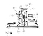
- FIG. 8 shows a side view of another inventive heel unit 201. Also in this illustration, the left in the heel counter 201 is front, while in the illustration right at the heel counter 201 is behind. In addition, at the top and bottom in the illustration also at the heel unit 201 above and below. As with the in the FIGS. 1 to 4 As well as heel machines 1, 101 shown in FIGS. 6 and 7, here too some, if any, elements which are less relevant to the invention, such as a base element, an actuating lever or climbing aids, are not shown.
- the arms 206.1, 206.2 are otherwise aligned vertically and are movable in the vertically oriented first plane, are in the in the FIG. 8 shown heel unit 201, the first and second mating member 208, 209 and the spindle 210 and the coil spring 213 horizontally aligned and movable in a horizontally oriented, second plane.
- the spindle 210 is aligned in the longitudinal direction of the ski and with its front end screwed into the second push element 209, which is arranged in front of the two arms 206.1, 206.2.
- the spindle 210 passes through an opening in the first push member 208 and passes through the housing 203 of the heel holder 202. With her head she stands backwards beyond the housing 203 of the heel holder 202 out.
- the first stub element 208 is movable relative to the spindle 210 along the spindle 210.
- the coil spring 213 is clamped between the first stub element 208 and the head of the spindle 210.
- the spindle 210 can be screwed by rotating the head of the spindle 210 about an axis aligned along the ski longitudinal axis depending on the direction of rotation in or out of the second push member 209, whereby the bias of the coil spring 213 can be adjusted.
- the spindle 210 can also be referred to as a coupling element, by which the first and the second push member 208, 209 are coupled together, so that the first push member 208 is pressed with a first force forward against the two arms 206.1, 206.2, while the second push member 209 is pressed with a second force back against the two arms 206.1, 206.2, wherein the first and the second force are equally strong.
- FIG. 9 shows a plan view of the heel unit 201.
- the invention is not limited to the three embodiments described above.
- Various variants of it are possible.
- the spindle for example, another coupling element can be used.
- the two Stossieri can be shaped differently.
- the heel machine can only with be formed a Stosselement. If it comprises two stamper elements, it is also possible that only one of the two stub elements is movable relative to the two arms. For example, one of the two stub elements can be firmly integrated in the housing of the heel holder.
- the coupling element is either firmly connected to the housing or other remaining heel holder, or that the coupling element is firmly integrated in the housing or other remaining heel holder.
- another elastic element can be provided instead of the spiral spring.
- a second elastic element may also be provided.
- an automatic heel which allows a setting of the safety release for a particularly sporty driving in a compact design of the heel unit.
- This automatic heel unit can be used for piste bindings or also for touring ski bindings of the first type and second type mentioned in the introduction.
Landscapes
- Footwear And Its Accessory, Manufacturing Method And Apparatuses (AREA)
Priority Applications (1)
| Application Number | Priority Date | Filing Date | Title |
|---|---|---|---|
| EP15405009.0A EP3053632B1 (fr) | 2015-02-03 | 2015-02-03 | Talonnière |
Applications Claiming Priority (1)
| Application Number | Priority Date | Filing Date | Title |
|---|---|---|---|
| EP15405009.0A EP3053632B1 (fr) | 2015-02-03 | 2015-02-03 | Talonnière |
Publications (2)
| Publication Number | Publication Date |
|---|---|
| EP3053632A1 true EP3053632A1 (fr) | 2016-08-10 |
| EP3053632B1 EP3053632B1 (fr) | 2018-09-26 |
Family
ID=52469782
Family Applications (1)
| Application Number | Title | Priority Date | Filing Date |
|---|---|---|---|
| EP15405009.0A Not-in-force EP3053632B1 (fr) | 2015-02-03 | 2015-02-03 | Talonnière |
Country Status (1)
| Country | Link |
|---|---|
| EP (1) | EP3053632B1 (fr) |
Cited By (5)
| Publication number | Priority date | Publication date | Assignee | Title |
|---|---|---|---|---|
| EP3120903A1 (fr) * | 2016-10-14 | 2017-01-25 | Fritschi AG - Swiss Bindings | Talonnière |
| IT201900012741A1 (it) * | 2019-07-24 | 2021-01-24 | Atk Sports S R L | Talloniera per attacco da sci |
| EP4032592A1 (fr) * | 2021-01-22 | 2022-07-27 | Salewa Sport AG | Fixation de planche de glisse pourvu d'un boîtier vissé dans la direction horizontale |
| EP4245386A1 (fr) * | 2022-03-17 | 2023-09-20 | Salewa Sport AG | Talonniere pour fixation de planche de glisse avec plaque de renfort |
| EP4272846A3 (fr) * | 2022-05-02 | 2023-11-29 | MARKER Deutschland GmbH | Talonnière avec réglage de résistance pour le déclenchement vertical |
Citations (8)
| Publication number | Priority date | Publication date | Assignee | Title |
|---|---|---|---|---|
| AT402020B (de) | 1993-08-19 | 1997-01-27 | Barthel Fritz | Fersenbacken für eine skibindung |
| EP0754079B1 (fr) | 1995-02-01 | 1999-04-28 | Fritschi Ag, Apparatebau | Fixation de ski |
| WO2009105866A1 (fr) * | 2008-02-29 | 2009-09-03 | G3 Genuine Guide Gear Inc. | Unité talon pour fixation de randonnée en montagne |
| EP2345463A1 (fr) * | 2010-01-19 | 2011-07-20 | Atk Race S.R.L. | Pièce de talon pour fixation de ski alpin |
| WO2012024809A1 (fr) | 2010-08-27 | 2012-03-01 | Fritschi Ag - Swiss Bindings | Fixation de ski de randonnée à talonnière comportant une zone de glissement dynamique |
| DE102011078834A1 (de) * | 2011-07-07 | 2013-01-10 | Micado Cad-Solutions Gmbh | Sicherheitsauslösevorrichtung für eine Skibindung |
| EP2656884A1 (fr) * | 2012-04-25 | 2013-10-30 | MARKER Deutschland GmbH | Fixation de ski légère avec une sécurité de déchaussement accrue |
| EP2705883A1 (fr) | 2012-09-11 | 2014-03-12 | Fritschi AG - Swiss Bindings | Automate de talon pour une fixation de ski |
-
2015
- 2015-02-03 EP EP15405009.0A patent/EP3053632B1/fr not_active Not-in-force
Patent Citations (8)
| Publication number | Priority date | Publication date | Assignee | Title |
|---|---|---|---|---|
| AT402020B (de) | 1993-08-19 | 1997-01-27 | Barthel Fritz | Fersenbacken für eine skibindung |
| EP0754079B1 (fr) | 1995-02-01 | 1999-04-28 | Fritschi Ag, Apparatebau | Fixation de ski |
| WO2009105866A1 (fr) * | 2008-02-29 | 2009-09-03 | G3 Genuine Guide Gear Inc. | Unité talon pour fixation de randonnée en montagne |
| EP2345463A1 (fr) * | 2010-01-19 | 2011-07-20 | Atk Race S.R.L. | Pièce de talon pour fixation de ski alpin |
| WO2012024809A1 (fr) | 2010-08-27 | 2012-03-01 | Fritschi Ag - Swiss Bindings | Fixation de ski de randonnée à talonnière comportant une zone de glissement dynamique |
| DE102011078834A1 (de) * | 2011-07-07 | 2013-01-10 | Micado Cad-Solutions Gmbh | Sicherheitsauslösevorrichtung für eine Skibindung |
| EP2656884A1 (fr) * | 2012-04-25 | 2013-10-30 | MARKER Deutschland GmbH | Fixation de ski légère avec une sécurité de déchaussement accrue |
| EP2705883A1 (fr) | 2012-09-11 | 2014-03-12 | Fritschi AG - Swiss Bindings | Automate de talon pour une fixation de ski |
Cited By (6)
| Publication number | Priority date | Publication date | Assignee | Title |
|---|---|---|---|---|
| EP3120903A1 (fr) * | 2016-10-14 | 2017-01-25 | Fritschi AG - Swiss Bindings | Talonnière |
| IT201900012741A1 (it) * | 2019-07-24 | 2021-01-24 | Atk Sports S R L | Talloniera per attacco da sci |
| EP3769823A1 (fr) * | 2019-07-24 | 2021-01-27 | Atk Sports S.R.L. | Talonnière de fixation de ski |
| EP4032592A1 (fr) * | 2021-01-22 | 2022-07-27 | Salewa Sport AG | Fixation de planche de glisse pourvu d'un boîtier vissé dans la direction horizontale |
| EP4245386A1 (fr) * | 2022-03-17 | 2023-09-20 | Salewa Sport AG | Talonniere pour fixation de planche de glisse avec plaque de renfort |
| EP4272846A3 (fr) * | 2022-05-02 | 2023-11-29 | MARKER Deutschland GmbH | Talonnière avec réglage de résistance pour le déclenchement vertical |
Also Published As
| Publication number | Publication date |
|---|---|
| EP3053632B1 (fr) | 2018-09-26 |
Similar Documents
| Publication | Publication Date | Title |
|---|---|---|
| EP2608853B1 (fr) | Butée arrière de randonnee avec plage de glissement dynamique | |
| EP3766550B1 (fr) | Dispositif automatique avant | |
| EP3053632B1 (fr) | Talonnière | |
| EP1971408B1 (fr) | Dispositif d'aide à la montée | |
| EP2705883B1 (fr) | Automate de talon pour une fixation de ski | |
| EP3566754B1 (fr) | Butée avant de fixation de ski | |
| EP3702005B1 (fr) | Talonnière | |
| EP3498345A1 (fr) | Fixation de ski légère à sécurité de déclenchement augmentée | |
| EP2813268A1 (fr) | Automate avant | |
| EP3120903B1 (fr) | Talonnière | |
| EP3195906B1 (fr) | Talonniere ayant une configuration de marche | |
| EP3345659B1 (fr) | Talonnière automatique pour une fixation de ski | |
| DE3120090A1 (de) | Sicherheitsskibindung | |
| CH706664B1 (de) | Skibindung. | |
| EP3167943B1 (fr) | Talonniere comprenant une structure d'appui de talon | |
| EP2821114B1 (fr) | Système de fixation de sécurité | |
| EP3851174A1 (fr) | Butée avant pour une fixation de ski | |
| EP2368608B1 (fr) | Aide à la montée | |
| EP2851108B1 (fr) | Mâchoire avant pour une fixation de ski | |
| EP3103525B1 (fr) | Talonnière | |
| CH705586A2 (de) | Frontautomat. | |
| EP2821113A1 (fr) | Butée avant dotée d'un moyen de chaussement | |
| EP3115089B1 (fr) | Talonnière | |
| EP2965791B1 (fr) | Unité de positionnement automatique d'avant de chaussure de skis pour fixation à ergots | |
| EP3266504A1 (fr) | Fixation de ski |
Legal Events
| Date | Code | Title | Description |
|---|---|---|---|
| PUAI | Public reference made under article 153(3) epc to a published international application that has entered the european phase |
Free format text: ORIGINAL CODE: 0009012 |
|
| AK | Designated contracting states |
Kind code of ref document: A1 Designated state(s): AL AT BE BG CH CY CZ DE DK EE ES FI FR GB GR HR HU IE IS IT LI LT LU LV MC MK MT NL NO PL PT RO RS SE SI SK SM TR |
|
| AX | Request for extension of the european patent |
Extension state: BA ME |
|
| 17P | Request for examination filed |
Effective date: 20161010 |
|
| RBV | Designated contracting states (corrected) |
Designated state(s): AL AT BE BG CH CY CZ DE DK EE ES FI FR GB GR HR HU IE IS IT LI LT LU LV MC MK MT NL NO PL PT RO RS SE SI SK SM TR |
|
| RIC1 | Information provided on ipc code assigned before grant |
Ipc: A63C 9/084 20120101ALI20170330BHEP Ipc: A63C 9/086 20120101ALI20170330BHEP Ipc: A63C 9/08 20120101AFI20170330BHEP |
|
| GRAP | Despatch of communication of intention to grant a patent |
Free format text: ORIGINAL CODE: EPIDOSNIGR1 |
|
| STAA | Information on the status of an ep patent application or granted ep patent |
Free format text: STATUS: GRANT OF PATENT IS INTENDED |
|
| INTG | Intention to grant announced |
Effective date: 20170531 |
|
| GRAJ | Information related to disapproval of communication of intention to grant by the applicant or resumption of examination proceedings by the epo deleted |
Free format text: ORIGINAL CODE: EPIDOSDIGR1 |
|
| STAA | Information on the status of an ep patent application or granted ep patent |
Free format text: STATUS: REQUEST FOR EXAMINATION WAS MADE |
|
| STAA | Information on the status of an ep patent application or granted ep patent |
Free format text: STATUS: EXAMINATION IS IN PROGRESS |
|
| INTC | Intention to grant announced (deleted) | ||
| 17Q | First examination report despatched |
Effective date: 20170821 |
|
| GRAP | Despatch of communication of intention to grant a patent |
Free format text: ORIGINAL CODE: EPIDOSNIGR1 |
|
| STAA | Information on the status of an ep patent application or granted ep patent |
Free format text: STATUS: GRANT OF PATENT IS INTENDED |
|
| INTG | Intention to grant announced |
Effective date: 20180622 |
|
| GRAS | Grant fee paid |
Free format text: ORIGINAL CODE: EPIDOSNIGR3 |
|
| GRAA | (expected) grant |
Free format text: ORIGINAL CODE: 0009210 |
|
| STAA | Information on the status of an ep patent application or granted ep patent |
Free format text: STATUS: THE PATENT HAS BEEN GRANTED |
|
| AK | Designated contracting states |
Kind code of ref document: B1 Designated state(s): AL AT BE BG CH CY CZ DE DK EE ES FI FR GB GR HR HU IE IS IT LI LT LU LV MC MK MT NL NO PL PT RO RS SE SI SK SM TR |
|
| REG | Reference to a national code |
Ref country code: GB Ref legal event code: FG4D Free format text: NOT ENGLISH |
|
| REG | Reference to a national code |
Ref country code: CH Ref legal event code: EP |
|
| REG | Reference to a national code |
Ref country code: CH Ref legal event code: NV Representative=s name: KELLER AND PARTNER PATENTANWAELTE AG, CH Ref country code: AT Ref legal event code: REF Ref document number: 1045313 Country of ref document: AT Kind code of ref document: T Effective date: 20181015 |
|
| REG | Reference to a national code |
Ref country code: IE Ref legal event code: FG4D Free format text: LANGUAGE OF EP DOCUMENT: GERMAN |
|
| REG | Reference to a national code |
Ref country code: DE Ref legal event code: R096 Ref document number: 502015006067 Country of ref document: DE |
|
| REG | Reference to a national code |
Ref country code: NL Ref legal event code: MP Effective date: 20180926 |
|
| PG25 | Lapsed in a contracting state [announced via postgrant information from national office to epo] |
Ref country code: SE Free format text: LAPSE BECAUSE OF FAILURE TO SUBMIT A TRANSLATION OF THE DESCRIPTION OR TO PAY THE FEE WITHIN THE PRESCRIBED TIME-LIMIT Effective date: 20180926 Ref country code: LT Free format text: LAPSE BECAUSE OF FAILURE TO SUBMIT A TRANSLATION OF THE DESCRIPTION OR TO PAY THE FEE WITHIN THE PRESCRIBED TIME-LIMIT Effective date: 20180926 Ref country code: RS Free format text: LAPSE BECAUSE OF FAILURE TO SUBMIT A TRANSLATION OF THE DESCRIPTION OR TO PAY THE FEE WITHIN THE PRESCRIBED TIME-LIMIT Effective date: 20180926 Ref country code: FI Free format text: LAPSE BECAUSE OF FAILURE TO SUBMIT A TRANSLATION OF THE DESCRIPTION OR TO PAY THE FEE WITHIN THE PRESCRIBED TIME-LIMIT Effective date: 20180926 Ref country code: NO Free format text: LAPSE BECAUSE OF FAILURE TO SUBMIT A TRANSLATION OF THE DESCRIPTION OR TO PAY THE FEE WITHIN THE PRESCRIBED TIME-LIMIT Effective date: 20181226 Ref country code: BG Free format text: LAPSE BECAUSE OF FAILURE TO SUBMIT A TRANSLATION OF THE DESCRIPTION OR TO PAY THE FEE WITHIN THE PRESCRIBED TIME-LIMIT Effective date: 20181226 Ref country code: GR Free format text: LAPSE BECAUSE OF FAILURE TO SUBMIT A TRANSLATION OF THE DESCRIPTION OR TO PAY THE FEE WITHIN THE PRESCRIBED TIME-LIMIT Effective date: 20181227 |
|
| REG | Reference to a national code |
Ref country code: LT Ref legal event code: MG4D |
|
| PG25 | Lapsed in a contracting state [announced via postgrant information from national office to epo] |
Ref country code: AL Free format text: LAPSE BECAUSE OF FAILURE TO SUBMIT A TRANSLATION OF THE DESCRIPTION OR TO PAY THE FEE WITHIN THE PRESCRIBED TIME-LIMIT Effective date: 20180926 Ref country code: HR Free format text: LAPSE BECAUSE OF FAILURE TO SUBMIT A TRANSLATION OF THE DESCRIPTION OR TO PAY THE FEE WITHIN THE PRESCRIBED TIME-LIMIT Effective date: 20180926 Ref country code: LV Free format text: LAPSE BECAUSE OF FAILURE TO SUBMIT A TRANSLATION OF THE DESCRIPTION OR TO PAY THE FEE WITHIN THE PRESCRIBED TIME-LIMIT Effective date: 20180926 |
|
| PG25 | Lapsed in a contracting state [announced via postgrant information from national office to epo] |
Ref country code: NL Free format text: LAPSE BECAUSE OF FAILURE TO SUBMIT A TRANSLATION OF THE DESCRIPTION OR TO PAY THE FEE WITHIN THE PRESCRIBED TIME-LIMIT Effective date: 20180926 Ref country code: PL Free format text: LAPSE BECAUSE OF FAILURE TO SUBMIT A TRANSLATION OF THE DESCRIPTION OR TO PAY THE FEE WITHIN THE PRESCRIBED TIME-LIMIT Effective date: 20180926 Ref country code: ES Free format text: LAPSE BECAUSE OF FAILURE TO SUBMIT A TRANSLATION OF THE DESCRIPTION OR TO PAY THE FEE WITHIN THE PRESCRIBED TIME-LIMIT Effective date: 20180926 Ref country code: EE Free format text: LAPSE BECAUSE OF FAILURE TO SUBMIT A TRANSLATION OF THE DESCRIPTION OR TO PAY THE FEE WITHIN THE PRESCRIBED TIME-LIMIT Effective date: 20180926 Ref country code: CZ Free format text: LAPSE BECAUSE OF FAILURE TO SUBMIT A TRANSLATION OF THE DESCRIPTION OR TO PAY THE FEE WITHIN THE PRESCRIBED TIME-LIMIT Effective date: 20180926 Ref country code: IT Free format text: LAPSE BECAUSE OF FAILURE TO SUBMIT A TRANSLATION OF THE DESCRIPTION OR TO PAY THE FEE WITHIN THE PRESCRIBED TIME-LIMIT Effective date: 20180926 Ref country code: RO Free format text: LAPSE BECAUSE OF FAILURE TO SUBMIT A TRANSLATION OF THE DESCRIPTION OR TO PAY THE FEE WITHIN THE PRESCRIBED TIME-LIMIT Effective date: 20180926 Ref country code: IS Free format text: LAPSE BECAUSE OF FAILURE TO SUBMIT A TRANSLATION OF THE DESCRIPTION OR TO PAY THE FEE WITHIN THE PRESCRIBED TIME-LIMIT Effective date: 20190126 |
|
| PG25 | Lapsed in a contracting state [announced via postgrant information from national office to epo] |
Ref country code: PT Free format text: LAPSE BECAUSE OF FAILURE TO SUBMIT A TRANSLATION OF THE DESCRIPTION OR TO PAY THE FEE WITHIN THE PRESCRIBED TIME-LIMIT Effective date: 20190126 Ref country code: SK Free format text: LAPSE BECAUSE OF FAILURE TO SUBMIT A TRANSLATION OF THE DESCRIPTION OR TO PAY THE FEE WITHIN THE PRESCRIBED TIME-LIMIT Effective date: 20180926 Ref country code: SM Free format text: LAPSE BECAUSE OF FAILURE TO SUBMIT A TRANSLATION OF THE DESCRIPTION OR TO PAY THE FEE WITHIN THE PRESCRIBED TIME-LIMIT Effective date: 20180926 |
|
| REG | Reference to a national code |
Ref country code: DE Ref legal event code: R097 Ref document number: 502015006067 Country of ref document: DE |
|
| PG25 | Lapsed in a contracting state [announced via postgrant information from national office to epo] |
Ref country code: DK Free format text: LAPSE BECAUSE OF FAILURE TO SUBMIT A TRANSLATION OF THE DESCRIPTION OR TO PAY THE FEE WITHIN THE PRESCRIBED TIME-LIMIT Effective date: 20180926 |
|
| PLBE | No opposition filed within time limit |
Free format text: ORIGINAL CODE: 0009261 |
|
| STAA | Information on the status of an ep patent application or granted ep patent |
Free format text: STATUS: NO OPPOSITION FILED WITHIN TIME LIMIT |
|
| 26N | No opposition filed |
Effective date: 20190627 |
|
| GBPC | Gb: european patent ceased through non-payment of renewal fee |
Effective date: 20190203 |
|
| PG25 | Lapsed in a contracting state [announced via postgrant information from national office to epo] |
Ref country code: MC Free format text: LAPSE BECAUSE OF FAILURE TO SUBMIT A TRANSLATION OF THE DESCRIPTION OR TO PAY THE FEE WITHIN THE PRESCRIBED TIME-LIMIT Effective date: 20180926 Ref country code: LU Free format text: LAPSE BECAUSE OF NON-PAYMENT OF DUE FEES Effective date: 20190203 Ref country code: SI Free format text: LAPSE BECAUSE OF FAILURE TO SUBMIT A TRANSLATION OF THE DESCRIPTION OR TO PAY THE FEE WITHIN THE PRESCRIBED TIME-LIMIT Effective date: 20180926 |
|
| REG | Reference to a national code |
Ref country code: BE Ref legal event code: MM Effective date: 20190228 |
|
| REG | Reference to a national code |
Ref country code: IE Ref legal event code: MM4A |
|
| PG25 | Lapsed in a contracting state [announced via postgrant information from national office to epo] |
Ref country code: IE Free format text: LAPSE BECAUSE OF NON-PAYMENT OF DUE FEES Effective date: 20190203 Ref country code: GB Free format text: LAPSE BECAUSE OF NON-PAYMENT OF DUE FEES Effective date: 20190203 |
|
| PG25 | Lapsed in a contracting state [announced via postgrant information from national office to epo] |
Ref country code: FR Free format text: LAPSE BECAUSE OF NON-PAYMENT OF DUE FEES Effective date: 20190228 Ref country code: BE Free format text: LAPSE BECAUSE OF NON-PAYMENT OF DUE FEES Effective date: 20190228 |
|
| PG25 | Lapsed in a contracting state [announced via postgrant information from national office to epo] |
Ref country code: TR Free format text: LAPSE BECAUSE OF FAILURE TO SUBMIT A TRANSLATION OF THE DESCRIPTION OR TO PAY THE FEE WITHIN THE PRESCRIBED TIME-LIMIT Effective date: 20180926 |
|
| PG25 | Lapsed in a contracting state [announced via postgrant information from national office to epo] |
Ref country code: MT Free format text: LAPSE BECAUSE OF FAILURE TO SUBMIT A TRANSLATION OF THE DESCRIPTION OR TO PAY THE FEE WITHIN THE PRESCRIBED TIME-LIMIT Effective date: 20180926 |
|
| REG | Reference to a national code |
Ref country code: CH Ref legal event code: PFA Owner name: FRITSCHI AG - SWISS BINDINGS, CH Free format text: FORMER OWNER: FRITSCHI AG - SWISS BINDINGS, CH |
|
| PG25 | Lapsed in a contracting state [announced via postgrant information from national office to epo] |
Ref country code: CY Free format text: LAPSE BECAUSE OF FAILURE TO SUBMIT A TRANSLATION OF THE DESCRIPTION OR TO PAY THE FEE WITHIN THE PRESCRIBED TIME-LIMIT Effective date: 20180926 |
|
| PGFP | Annual fee paid to national office [announced via postgrant information from national office to epo] |
Ref country code: AT Payment date: 20210209 Year of fee payment: 7 |
|
| PG25 | Lapsed in a contracting state [announced via postgrant information from national office to epo] |
Ref country code: HU Free format text: LAPSE BECAUSE OF FAILURE TO SUBMIT A TRANSLATION OF THE DESCRIPTION OR TO PAY THE FEE WITHIN THE PRESCRIBED TIME-LIMIT; INVALID AB INITIO Effective date: 20150203 |
|
| PGFP | Annual fee paid to national office [announced via postgrant information from national office to epo] |
Ref country code: CH Payment date: 20220112 Year of fee payment: 8 |
|
| PG25 | Lapsed in a contracting state [announced via postgrant information from national office to epo] |
Ref country code: MK Free format text: LAPSE BECAUSE OF FAILURE TO SUBMIT A TRANSLATION OF THE DESCRIPTION OR TO PAY THE FEE WITHIN THE PRESCRIBED TIME-LIMIT Effective date: 20180926 |
|
| PGFP | Annual fee paid to national office [announced via postgrant information from national office to epo] |
Ref country code: DE Payment date: 20220427 Year of fee payment: 8 |
|
| REG | Reference to a national code |
Ref country code: AT Ref legal event code: MM01 Ref document number: 1045313 Country of ref document: AT Kind code of ref document: T Effective date: 20220203 |
|
| PG25 | Lapsed in a contracting state [announced via postgrant information from national office to epo] |
Ref country code: AT Free format text: LAPSE BECAUSE OF NON-PAYMENT OF DUE FEES Effective date: 20220203 |
|
| REG | Reference to a national code |
Ref country code: DE Ref legal event code: R119 Ref document number: 502015006067 Country of ref document: DE |
|
| REG | Reference to a national code |
Ref country code: CH Ref legal event code: PL |
|
| PG25 | Lapsed in a contracting state [announced via postgrant information from national office to epo] |
Ref country code: LI Free format text: LAPSE BECAUSE OF NON-PAYMENT OF DUE FEES Effective date: 20230228 Ref country code: CH Free format text: LAPSE BECAUSE OF NON-PAYMENT OF DUE FEES Effective date: 20230228 |
|
| PG25 | Lapsed in a contracting state [announced via postgrant information from national office to epo] |
Ref country code: DE Free format text: LAPSE BECAUSE OF NON-PAYMENT OF DUE FEES Effective date: 20230901 |