EP0747713A2 - Circuit capteur de courant de charge d'un composant semi-conducteur de puissance avec charge soit à la borne de source ou soit à la bornne de drain - Google Patents
Circuit capteur de courant de charge d'un composant semi-conducteur de puissance avec charge soit à la borne de source ou soit à la bornne de drain Download PDFInfo
- Publication number
- EP0747713A2 EP0747713A2 EP96108434A EP96108434A EP0747713A2 EP 0747713 A2 EP0747713 A2 EP 0747713A2 EP 96108434 A EP96108434 A EP 96108434A EP 96108434 A EP96108434 A EP 96108434A EP 0747713 A2 EP0747713 A2 EP 0747713A2
- Authority
- EP
- European Patent Office
- Prior art keywords
- semiconductor component
- circuit arrangement
- source
- mosfet
- resistor
- Prior art date
- Legal status (The legal status is an assumption and is not a legal conclusion. Google has not performed a legal analysis and makes no representation as to the accuracy of the status listed.)
- Granted
Links
Images

Classifications
-
- G—PHYSICS
- G01—MEASURING; TESTING
- G01R—MEASURING ELECTRIC VARIABLES; MEASURING MAGNETIC VARIABLES
- G01R19/00—Arrangements for measuring currents or voltages or for indicating presence or sign thereof
-
- G—PHYSICS
- G05—CONTROLLING; REGULATING
- G05F—SYSTEMS FOR REGULATING ELECTRIC OR MAGNETIC VARIABLES
- G05F3/00—Non-retroactive systems for regulating electric variables by using an uncontrolled element, or an uncontrolled combination of elements, such element or such combination having self-regulating properties
- G05F3/02—Regulating voltage or current
- G05F3/08—Regulating voltage or current wherein the variable is DC
- G05F3/10—Regulating voltage or current wherein the variable is DC using uncontrolled devices with non-linear characteristics
- G05F3/16—Regulating voltage or current wherein the variable is DC using uncontrolled devices with non-linear characteristics being semiconductor devices
- G05F3/20—Regulating voltage or current wherein the variable is DC using uncontrolled devices with non-linear characteristics being semiconductor devices using diode- transistor combinations
- G05F3/24—Regulating voltage or current wherein the variable is DC using uncontrolled devices with non-linear characteristics being semiconductor devices using diode- transistor combinations wherein the transistors are of the field-effect type only
-
- G—PHYSICS
- G01—MEASURING; TESTING
- G01R—MEASURING ELECTRIC VARIABLES; MEASURING MAGNETIC VARIABLES
- G01R1/00—Details of instruments or arrangements of the types included in groups G01R5/00 - G01R13/00 and G01R31/00
- G01R1/20—Modifications of basic electric elements for use in electric measuring instruments; Structural combinations of such elements with such instruments
- G01R1/203—Resistors used for electric measuring, e.g. decade resistors standards, resistors for comparators, series resistors, shunts
-
- G—PHYSICS
- G01—MEASURING; TESTING
- G01R—MEASURING ELECTRIC VARIABLES; MEASURING MAGNETIC VARIABLES
- G01R19/00—Arrangements for measuring currents or voltages or for indicating presence or sign thereof
- G01R19/0092—Measuring current only
-
- H—ELECTRICITY
- H03—ELECTRONIC CIRCUITRY
- H03K—PULSE TECHNIQUE
- H03K17/00—Electronic switching or gating, i.e. not by contact-making and –breaking
- H03K17/14—Modifications for compensating variations of physical values, e.g. of temperature
- H03K17/145—Modifications for compensating variations of physical values, e.g. of temperature in field-effect transistor switches
-
- H—ELECTRICITY
- H03—ELECTRONIC CIRCUITRY
- H03K—PULSE TECHNIQUE
- H03K2217/00—Indexing scheme related to electronic switching or gating, i.e. not by contact-making or -breaking covered by H03K17/00
- H03K2217/0027—Measuring means of, e.g. currents through or voltages across the switch
Definitions
- the prerequisite is that the measuring resistor is matched to the load. With a different load, either the measuring resistance must be changed or the evaluation logic that detects the voltage.
- the invention has for its object to develop a circuit of the type mentioned so that it can be used regardless of the size of the load. In addition, it should be usable for the most common case of the "high-side" switch.
- the resistor is connected on the one hand to a terminal which is at a fixed potential and on the other hand via a controllable resistor to the source terminal of the further semiconductor component, and in that the current of the further semiconductor component is set by the controllable resistor in such a way that the drain -Source voltages of both semiconductor components are equal to one another.
- the circuit according to FIG. 1 contains a power MOSFET 1 to which a load 4 is connected in series on the source side. It therefore represents a high-side switch.
- the circuit also contains a further MOSFET 2.
- the drain connections D of both MOSFETs are connected to one another, as are their gate connections. Your source connections are separated.
- a controllable resistor 6 is connected to the source terminal of the MOSFET 2.
- the controllable resistor on the other hand, is connected to a measuring resistor 5 via a connection 10.
- the other connection of the measuring resistor 5 is at a fixed potential, preferably to ground. This mass can, but does not have to be identical to that on which the load 4 lies.
- the controllable resistor 6 is expediently designed as a MOSFET. Then its source connection is connected to the measuring resistor 5 and its drain connection to the source connection of the MOSFET 2. It is of the reverse channel type as the MOSFET 2. The gate connection of the MOSFET 6 is connected to the output of a differential amplifier 3. This has two inputs, of which the negative input is connected to the source terminal of the MOSFET 2 and the positive input is connected to the source terminal of the power MOSFET 1.
- the entire arrangement is based on an operating voltage + V bb , which is applied between a terminal 11 and ground.
- the connection 11 is connected to the drain connections of the MOSFET 1 and 2.
- the gate connections of both MOSFETs are connected via a resistor 8 to an input 9, to which a control voltage can be applied, for example via a pump circuit.
- the drain-source voltage at the power MOSFET 1 increases or decreases and thus the variable resistor 6 is controlled in the direction of lower or higher resistance until the voltage difference at the input of the amplifier 3 is zero.
- a prerequisite for the fixed proportionality is that the I D / U DS characteristics of MOSFET 1 and 2 are similar to each other. Ie that for each voltage value U DS a current flows through the further FET 2, which is a fixed fraction of the load current. At the resistor 5, this current generates a voltage which is related to ground and is proportional to the load current and which can be tapped at the terminal 10.
- the similarity can easily be achieved in that, as mentioned at the beginning, the MOSFET 2 is formed by some cells of the power MOSFET 1.
- the ratio can be, for example, 10: 10,000.
- the circuit arrangement according to FIG. 2 differs from that according to FIG. 1 by an additional differential amplifier 14, the first input of which is connected to the source connection of the power MOSFET 1.
- a fixed voltage is present at the other input of the differential amplifier 14.
- the output of 14 is connected to the gate terminals of MOSFET 1 and 2.
- the increase in the drain-source voltage at the MOSFET 1 by, for example, 0.1 V increases the on-state resistance of the power MOSFET only insignificantly. The increase in losses in power MOSFET 1 is thus negligible.
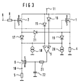
- the negative input of the amplifier 3 is connected to the terminal 11 via a diode 15 and to ground via a current source 18.
- the other output is connected to terminal 11 via a diode 16 and to ground via a current source 20.
- the negative input is also connected via a diode 17 to the source terminal of the MOSFET 2, the positive input via a diode 19 to the source terminal of the power MOSFET 1.
- the diodes and current sources serve to set the amplifier 3 to the correct operating point. All diodes can be designed as MOS diodes, the current sources can be implemented as a current mirror circuit or as a depletion MOSFET.
- a resistor 21 may be connected between the output of the amplifier 3 and the gate connection of the MOSFET 6, the connection of which is connected to the cat connection of 6 and connected to a capacitor 22.
- the other connection of the capacitor is grounded.
- This RC combination counteracts the tendency of amplifier 3 to oscillate.
- the amplifier 3 is expediently an operational amplifier.
- the circuit according to the invention can be operated essentially independently of temperature if the measuring resistor 5 itself is independent of temperature or not very dependent on temperature. This can e.g. can be achieved in that the measuring resistor 5 consists of polysilicon or is designed as a temperature-compensated resistor.
- the invention was explained using a high-side switch. However, it can also be used for a low-side switch.
- the load 4 is located on the drain side of the two MOSFETs, while the controllable switch 6 and the measuring resistor 5 remain connected on the source side of the MOSFET 2.
Landscapes
- Physics & Mathematics (AREA)
- Engineering & Computer Science (AREA)
- General Physics & Mathematics (AREA)
- Microelectronics & Electronic Packaging (AREA)
- Nonlinear Science (AREA)
- Electromagnetism (AREA)
- Radar, Positioning & Navigation (AREA)
- Automation & Control Theory (AREA)
- Amplifiers (AREA)
- Measurement Of Current Or Voltage (AREA)
- Control Of Voltage And Current In General (AREA)
- Testing Of Individual Semiconductor Devices (AREA)
Applications Claiming Priority (2)
| Application Number | Priority Date | Filing Date | Title |
|---|---|---|---|
| DE19520735A DE19520735C2 (de) | 1995-06-07 | 1995-06-07 | Schaltungsanordnung zum Erfassen des Laststroms eines Leistungs-Halbleiterbauelementes mit sourceseitiger Last |
| DE19520735 | 1995-06-07 |
Publications (3)
| Publication Number | Publication Date |
|---|---|
| EP0747713A2 true EP0747713A2 (fr) | 1996-12-11 |
| EP0747713A3 EP0747713A3 (fr) | 1998-01-07 |
| EP0747713B1 EP0747713B1 (fr) | 2006-07-12 |
Family
ID=7763807
Family Applications (1)
| Application Number | Title | Priority Date | Filing Date |
|---|---|---|---|
| EP96108434A Expired - Lifetime EP0747713B1 (fr) | 1995-06-07 | 1996-05-28 | Circuit capteur de courant de charge d'un composant semi-conducteur de puissance avec charge soit à la borne de source ou soit à la borne de drain |
Country Status (5)
| Country | Link |
|---|---|
| US (1) | US5815027A (fr) |
| EP (1) | EP0747713B1 (fr) |
| JP (1) | JPH08334534A (fr) |
| KR (1) | KR970002339A (fr) |
| DE (2) | DE19520735C2 (fr) |
Cited By (8)
| Publication number | Priority date | Publication date | Assignee | Title |
|---|---|---|---|---|
| GB2322488A (en) * | 1997-02-21 | 1998-08-26 | Daimler Benz Ag | Battery monitor and circuit breaker |
| EP1028526A3 (fr) * | 1999-02-14 | 2001-02-07 | Yazaki Corporation | Circuit de détection de courants de fuites |
| WO2006129275A1 (fr) * | 2005-06-01 | 2006-12-07 | Nxp B.V. | Circuit et procede permettant de determiner le courant dans une charge |
| WO2009092788A2 (fr) | 2008-01-25 | 2009-07-30 | Continental Teves Ag & Co. Ohg | Système de circuit électronique pour détecter un courant d'élément de détection et/ou une température à l'intérieur de cet élément de détection |
| EP1953557A4 (fr) * | 2005-10-27 | 2012-06-20 | Renesas Electronics Corp | Circuit de detection de courant |
| CN108270197A (zh) * | 2016-12-30 | 2018-07-10 | 英飞凌科技股份有限公司 | 电子开关及其操作方法 |
| CN109073683A (zh) * | 2016-04-25 | 2018-12-21 | 大陆汽车有限公司 | 用于确定负载电流的方法及电池传感器 |
| IT201700091896A1 (it) * | 2017-08-08 | 2019-02-08 | Stmicroelectronics Shenzhen R&D Co Ltd | Circuito rilevatore di corrente, dispositivo e procedimento corrispondenti |
Families Citing this family (50)
| Publication number | Priority date | Publication date | Assignee | Title |
|---|---|---|---|---|
| ITMI981217A1 (it) * | 1997-06-05 | 1999-12-02 | Denso Corp | Struttura perfezionata per un circuito di misura di corrente |
| DE19812920C2 (de) * | 1998-03-24 | 2000-09-07 | Siemens Ag | Schaltungsanordnung zur Steuerung und Erfassung des Laststromes durch eine Last |
| DE69920159T2 (de) * | 1998-06-09 | 2005-09-29 | Koninklijke Philips Electronics N.V. | Strommessvorrichtung und telefonendgerät unter verwendung einer solchen strommessvorrichtung |
| DE19830356C1 (de) * | 1998-07-07 | 1999-11-11 | Siemens Ag | Verfahren zum Abgleichen eines Widerstands in einer integrierten Schaltung und Vorrichtung zur Durchführung dieses Verfahrens |
| DE19838657B4 (de) * | 1998-08-25 | 2008-01-24 | Infineon Technologies Ag | Schaltungsanordnung zum Erfassen des Laststromes eines Leistungs-Feldeffekt-Halbleiterbauelementes |
| GB9908285D0 (en) * | 1999-04-13 | 1999-06-02 | Koninkl Philips Electronics Nv | A power switching circuit |
| DE10019240A1 (de) * | 2000-04-18 | 2001-10-31 | Fujitsu Siemens Computers Gmbh | Schaltungsanordnung zur Messung der Stromaufnahme einer transistorgesteuerten Last |
| DE10057486A1 (de) | 2000-06-15 | 2016-10-13 | Continental Teves Ag & Co. Ohg | Verfahren und Schaltungsanordnung zur Erkennung eines Defekts von Halbleiterschaftelementen und dessen/deren Verwendung in Kraftfahrzeugen, insbesondere Bremskraft- und Fahrdynamikreglern |
| DE10032260B4 (de) * | 2000-07-03 | 2004-04-29 | Texas Instruments Deutschland Gmbh | Schaltungsanordnung zur Verdoppelung der Spannung einer Batterie |
| DE60110466D1 (de) | 2000-10-13 | 2005-06-02 | Primarion Inc | System und verfahren zur strommessung |
| US6407532B1 (en) * | 2000-12-29 | 2002-06-18 | Nokia Mobile Phones, Ltd. | Method and apparatus for measuring battery charge and discharge current |
| US7047119B2 (en) | 2001-01-23 | 2006-05-16 | Continental Teves Ag & Co., Ohg | Circuit arrangement and method for measuring current in vehicle braking systems |
| DE10103920A1 (de) | 2001-01-30 | 2002-08-22 | Infineon Technologies Ag | Schaltungsanordnung mit einem Lasttransistor und einer Strommessanordnung |
| DE10120524B4 (de) * | 2001-04-26 | 2015-08-20 | Infineon Technologies Ag | Vorrichtung zur Ermittlung des Stromes durch ein Leistungs-Halbleiterbauelement |
| ATE495454T1 (de) * | 2002-04-02 | 2011-01-15 | Dialog Semiconductor Gmbh | Leistungsschalter mit stromabfühlschaltung |
| DE10240914B4 (de) | 2002-09-04 | 2007-01-25 | Infineon Technologies Ag | Schaltungsanordnung mit einem Lasttransistor und einer Strommessanordnung und Verfahren zur Ermittlung des Laststroms eines Lasttransistors sowie Verwendung eines Halbleiterbauelements |
| GB0312237D0 (en) * | 2003-05-29 | 2003-07-02 | Koninkl Philips Electronics Nv | Undercurrent sense arrangement and method |
| DE102005009544B4 (de) * | 2005-03-02 | 2008-09-04 | Infineon Technologies Ag | Bauelementanordnung mit einem Lasttransistor und einem Messtransistor |
| DE102005010337B4 (de) | 2005-03-07 | 2013-02-21 | Infineon Technologies Austria Ag | Bauelementanordnung mit einem Bipolartransistor und einem Lastunterbrechungsdetektor |
| DE102005019955A1 (de) | 2005-04-29 | 2006-11-02 | Infineon Technologies Ag | Variables Ansteuermodul zur Ansteuerung einer Last |
| GB2431739A (en) * | 2005-10-27 | 2007-05-02 | Wolfson Microelectronics Plc | Switch current sensing circuit |
| KR101221799B1 (ko) * | 2005-11-21 | 2013-01-14 | 페어차일드코리아반도체 주식회사 | 전류감지 회로 및 이를 구비한 부스트 컨버터 |
| DE102006037554B3 (de) * | 2006-08-10 | 2007-11-22 | Infineon Technologies Ag | Verfahren zur Einstellung eines Bezugspotentials eines Stromfühlers und Anordnung zur Bestimmung des Bezugspotentials einer Leistungshalbleitereinrichtung |
| JP2009075957A (ja) * | 2007-09-21 | 2009-04-09 | Renesas Technology Corp | 電源回路および半導体装置 |
| JP5044448B2 (ja) * | 2008-03-03 | 2012-10-10 | ルネサスエレクトロニクス株式会社 | 電源スイッチ回路 |
| US20090295369A1 (en) * | 2008-06-02 | 2009-12-03 | Yang Doris | Current sensing circuit |
| JP5171406B2 (ja) * | 2008-06-05 | 2013-03-27 | 矢崎総業株式会社 | 負荷回路の過電流保護装置 |
| DE102008044634B4 (de) | 2008-08-27 | 2017-12-21 | Fraunhofer-Gesellschaft zur Förderung der angewandten Forschung e.V. | Vorrichtung und Verfahren zum Erfassen eines Durchschnittswerts eines geschalteten Stromes in einer Spule |
| US7911260B2 (en) | 2009-02-02 | 2011-03-22 | Infineon Technologies Ag | Current control circuits |
| US8643068B2 (en) * | 2009-03-12 | 2014-02-04 | Infineon Technologies Ag | Integrated circuit having field effect transistors and manufacturing method |
| DE102009001899B4 (de) | 2009-03-26 | 2024-01-18 | Robert Bosch Gmbh | Messen eines Laststroms eines Unterbrechers |
| US20110185179A1 (en) * | 2009-08-26 | 2011-07-28 | Viswanathan Swaminathan | System And Method For Digital Rights Management With A Lightweight Digital Watermarking Component |
| WO2012137670A1 (fr) * | 2011-04-05 | 2012-10-11 | ルネサスエレクトロニクス株式会社 | Circuit de détection d'un courant de charge |
| US8493136B2 (en) * | 2011-04-08 | 2013-07-23 | Icera Inc. | Driver circuit and a mixer circuit receiving a signal from the driver circuit |
| EP2746890B1 (fr) * | 2012-12-19 | 2017-09-27 | Nxp B.V. | Circuits et procédés de surveillance de courant |
| WO2014121484A1 (fr) * | 2013-02-07 | 2014-08-14 | Texas Instruments Incorporated | Entrée bidirectionnelle, sortie bidirectionnelle, schéma de détection de courant sans perte avec compensation de température |
| US9853533B2 (en) * | 2013-04-25 | 2017-12-26 | Infineon Technologies Austria Ag | Circuit arrangement and method for reproducing a current |
| US9360879B2 (en) * | 2014-04-28 | 2016-06-07 | Microsemi Corp.-Analog Mixed Signal Group, Ltd. | Sense current generation apparatus and method |
| US9829387B2 (en) | 2014-10-28 | 2017-11-28 | Infineon Technologies Austria Ag | System and method for temperature sensing |
| JP2016200570A (ja) | 2015-04-14 | 2016-12-01 | ルネサスエレクトロニクス株式会社 | 半導体装置の電流検出方法および半導体装置 |
| JP2017069412A (ja) | 2015-09-30 | 2017-04-06 | ルネサスエレクトロニクス株式会社 | 半導体装置 |
| JP2018031705A (ja) * | 2016-08-25 | 2018-03-01 | 株式会社デンソー | 半導体装置 |
| US10014851B2 (en) | 2016-11-02 | 2018-07-03 | Texas Instruments Incorporated | Current sensing and control for a transistor power switch |
| US11243235B2 (en) * | 2018-07-06 | 2022-02-08 | Texas Instruments Incorporated | Load current sensing at low output voltage |
| JP7085017B2 (ja) * | 2018-11-06 | 2022-06-15 | 日立Astemo株式会社 | 負荷駆動装置及び変速機の駆動システム |
| US11239656B2 (en) * | 2019-07-19 | 2022-02-01 | Texas Instruments Incorporated | Methods and apparatus for current sensing and current limiting |
| JP2021047057A (ja) * | 2019-09-17 | 2021-03-25 | ルネサスエレクトロニクス株式会社 | 半導体装置、および、パワーデバイス |
| JP7391720B2 (ja) * | 2020-03-05 | 2023-12-05 | 株式会社東芝 | 半導体集積回路装置および電流検出回路 |
| DE102021206080A1 (de) * | 2021-06-15 | 2022-12-15 | Robert Bosch Gesellschaft mit beschränkter Haftung | Integrierte Schaltung und Verfahren zum Begrenzen eines schaltbaren Laststroms |
| US12313660B2 (en) * | 2023-03-27 | 2025-05-27 | Texas Instruments Incorporated | Methods and apparatus to improve accuracy of current sense circuitry |
Family Cites Families (9)
| Publication number | Priority date | Publication date | Assignee | Title |
|---|---|---|---|---|
| NL8503394A (nl) * | 1985-12-10 | 1987-07-01 | Philips Nv | Stroomaftastschakeling voor een vermogenshalfgeleiderinrichting, in het bijzonder geintegreerde intelligente vermogenshalfgeleiderschakelaar voor met name automobieltoepassingen. |
| AT388944B (de) * | 1986-05-27 | 1989-09-25 | Austria Antriebstech | Verfahren und einrichtung zur ueberwachung der funktion einer waschmaschine |
| IT1213415B (it) * | 1986-12-17 | 1989-12-20 | Sgs Microelettronica Spa | Circuito per la misura lineare della corrente circolante su un carico. |
| GB2206010A (en) * | 1987-06-08 | 1988-12-21 | Philips Electronic Associated | Differential amplifier and current sensing circuit including such an amplifier |
| US5097456A (en) * | 1987-10-28 | 1992-03-17 | Oki Electric Industry Co., Ltd. | Optical head |
| FR2628217B1 (fr) | 1988-03-07 | 1990-07-27 | Sgs Thomson Microelectronics | Circuit de mesure d'un courant |
| FR2642176B1 (fr) * | 1989-01-20 | 1991-05-03 | Sgs Thomson Microelectronics | Dispositif et procede de detection du passage d'un courant dans un transistor mos |
| FR2656932B1 (fr) * | 1990-01-09 | 1992-05-07 | Sgs Thomson Microelectronics | Circuit de mesure du courant dans un transistor mos de puissance. |
| GB9222455D0 (en) * | 1992-10-26 | 1992-12-09 | Philips Electronics Uk Ltd | A current sensing circuit |
-
1995
- 1995-06-07 DE DE19520735A patent/DE19520735C2/de not_active Expired - Fee Related
-
1996
- 1996-05-28 DE DE59611364T patent/DE59611364D1/de not_active Expired - Lifetime
- 1996-05-28 EP EP96108434A patent/EP0747713B1/fr not_active Expired - Lifetime
- 1996-06-05 JP JP8165204A patent/JPH08334534A/ja active Pending
- 1996-06-05 KR KR1019960019929A patent/KR970002339A/ko not_active Abandoned
- 1996-06-07 US US08/660,500 patent/US5815027A/en not_active Expired - Lifetime
Cited By (17)
| Publication number | Priority date | Publication date | Assignee | Title |
|---|---|---|---|---|
| GB2322488A (en) * | 1997-02-21 | 1998-08-26 | Daimler Benz Ag | Battery monitor and circuit breaker |
| GB2322488B (en) * | 1997-02-21 | 1999-01-06 | Daimler Benz Ag | Battery monitoring unit |
| US5977751A (en) * | 1997-02-21 | 1999-11-02 | Daimler-Benz Aktiengesellschaft | Battery monitoring unit having a sense FET circuit arrangement |
| EP1028526A3 (fr) * | 1999-02-14 | 2001-02-07 | Yazaki Corporation | Circuit de détection de courants de fuites |
| US6313690B1 (en) | 1999-02-14 | 2001-11-06 | Yazaki Corporation | Semiconductor switching device with leakage current detecting junction |
| US7952333B2 (en) | 2005-06-01 | 2011-05-31 | Nxp B.V. | Circuit and method for determining current in a load |
| WO2006129275A1 (fr) * | 2005-06-01 | 2006-12-07 | Nxp B.V. | Circuit et procede permettant de determiner le courant dans une charge |
| EP1953557A4 (fr) * | 2005-10-27 | 2012-06-20 | Renesas Electronics Corp | Circuit de detection de courant |
| WO2009092788A2 (fr) | 2008-01-25 | 2009-07-30 | Continental Teves Ag & Co. Ohg | Système de circuit électronique pour détecter un courant d'élément de détection et/ou une température à l'intérieur de cet élément de détection |
| WO2009092788A3 (fr) * | 2008-01-25 | 2010-12-23 | Continental Teves Ag & Co. Ohg | Système de circuit électronique pour détecter un courant d'élément de détection et/ou une température à l'intérieur de cet élément de détection |
| CN109073683A (zh) * | 2016-04-25 | 2018-12-21 | 大陆汽车有限公司 | 用于确定负载电流的方法及电池传感器 |
| CN108270197A (zh) * | 2016-12-30 | 2018-07-10 | 英飞凌科技股份有限公司 | 电子开关及其操作方法 |
| US10498131B2 (en) | 2016-12-30 | 2019-12-03 | Infineon Technologies Ag | Electronic switch and protection circuit |
| CN108270197B (zh) * | 2016-12-30 | 2020-01-17 | 英飞凌科技股份有限公司 | 电子开关及其操作方法 |
| IT201700091896A1 (it) * | 2017-08-08 | 2019-02-08 | Stmicroelectronics Shenzhen R&D Co Ltd | Circuito rilevatore di corrente, dispositivo e procedimento corrispondenti |
| EP3442121A1 (fr) * | 2017-08-08 | 2019-02-13 | STMicroelectronics (Shenzhen) R&D Co., Ltd. | Circuit de détection de courant, dispositif et procédé correspondants |
| US10935592B2 (en) | 2017-08-08 | 2021-03-02 | Stmicroelectronics S.R.L. | Current sensing circuit and method |
Also Published As
| Publication number | Publication date |
|---|---|
| DE19520735A1 (de) | 1996-12-12 |
| DE19520735C2 (de) | 1999-07-01 |
| KR970002339A (ko) | 1997-01-24 |
| EP0747713A3 (fr) | 1998-01-07 |
| US5815027A (en) | 1998-09-29 |
| DE59611364D1 (de) | 2006-08-24 |
| EP0747713B1 (fr) | 2006-07-12 |
| JPH08334534A (ja) | 1996-12-17 |
Similar Documents
| Publication | Publication Date | Title |
|---|---|---|
| EP0747713B1 (fr) | Circuit capteur de courant de charge d'un composant semi-conducteur de puissance avec charge soit à la borne de source ou soit à la borne de drain | |
| EP0665634B1 (fr) | Circuit avec un transistor à effet de champ | |
| EP0239862B1 (fr) | Circuit de commande pour un transistor de puissance MOSFET ayant une charge connectée à sa source | |
| EP0557850B1 (fr) | Montage servant à limiter le courant de charge d'un MOSFET de puissance | |
| EP0281684B1 (fr) | Commutateur à transistors Darlington protégé contre des surtensions | |
| EP0108283A2 (fr) | Commutateur électronique | |
| DE102015104946B4 (de) | Elektronische Treiberschaltung und Verfahren | |
| EP0236967B1 (fr) | Montage pour la commande d'un MOSFET dont la source est connectée à une charge | |
| DE102015102878B4 (de) | Elektronische Ansteuerschaltung | |
| EP0352659B1 (fr) | Circuit pour déterminer des court-circuits dans une charge en série avec un FET | |
| DE102016112162A1 (de) | Elektronische schalt- und verpolschutzschaltung | |
| EP0582125B1 (fr) | Circuit de commande pour un MOSFET de puissance ayant une charge connectée à la source | |
| DE4444623A1 (de) | Schaltungsanordnung zur Laststromregelung eines Leistungs-MOSFET | |
| DE19838657B4 (de) | Schaltungsanordnung zum Erfassen des Laststromes eines Leistungs-Feldeffekt-Halbleiterbauelementes | |
| EP0201878A2 (fr) | Circuit à transistor MOS à canal N commutant un potentiel positif | |
| DE2061943C3 (de) | Differenzverstärker | |
| DE4403201C2 (de) | Ansteuerschaltung für ein MOS-Halbleiterbauelement mit sourceseitiger Last | |
| DE69023358T2 (de) | Logische Schaltung. | |
| EP0205158B1 (fr) | Commutateur électronique | |
| EP0560086B1 (fr) | Circuit de protection pour un transistor à effet de champ MOS de puissance attaquant une charge inductive | |
| DE2653484A1 (de) | Integrierbarer konstantwiderstand | |
| DE3234602C2 (fr) | ||
| EP1189349A1 (fr) | Montage en parallèle d'une pluralité de transistors bipolaires à grille isolée | |
| EP0961403B1 (fr) | Circuit amplificateur intégré compensé en température | |
| EP0735351B1 (fr) | Montage de circuit pour détecter la température d'un élément semi-conducteur de puissance |
Legal Events
| Date | Code | Title | Description |
|---|---|---|---|
| PUAI | Public reference made under article 153(3) epc to a published international application that has entered the european phase |
Free format text: ORIGINAL CODE: 0009012 |
|
| AK | Designated contracting states |
Kind code of ref document: A2 Designated state(s): DE FR GB IT |
|
| PUAL | Search report despatched |
Free format text: ORIGINAL CODE: 0009013 |
|
| AK | Designated contracting states |
Kind code of ref document: A3 Designated state(s): DE FR GB IT |
|
| 17P | Request for examination filed |
Effective date: 19980205 |
|
| RAP1 | Party data changed (applicant data changed or rights of an application transferred) |
Owner name: INFINEON TECHNOLOGIES AG |
|
| GRAP | Despatch of communication of intention to grant a patent |
Free format text: ORIGINAL CODE: EPIDOSNIGR1 |
|
| GRAS | Grant fee paid |
Free format text: ORIGINAL CODE: EPIDOSNIGR3 |
|
| GRAA | (expected) grant |
Free format text: ORIGINAL CODE: 0009210 |
|
| AK | Designated contracting states |
Kind code of ref document: B1 Designated state(s): DE FR GB IT |
|
| PG25 | Lapsed in a contracting state [announced via postgrant information from national office to epo] |
Ref country code: IT Free format text: LAPSE BECAUSE OF FAILURE TO SUBMIT A TRANSLATION OF THE DESCRIPTION OR TO PAY THE FEE WITHIN THE PRE;WARNING: LAPSES OF ITALIAN PATENTS WITH EFFECTIVE DATE BEFORE 2007 MAY HAVE OCCURRED AT ANY TIME BEFORE 2007. THE CORRECT EFFECTIVE DATE MAY BE DIFFERENT FROM THE ONE RECORDED.SCRIBED TIME-LIMIT Effective date: 20060712 Ref country code: GB Free format text: LAPSE BECAUSE OF FAILURE TO SUBMIT A TRANSLATION OF THE DESCRIPTION OR TO PAY THE FEE WITHIN THE PRESCRIBED TIME-LIMIT Effective date: 20060712 |
|
| REG | Reference to a national code |
Ref country code: GB Ref legal event code: FG4D Free format text: NOT ENGLISH |
|
| REF | Corresponds to: |
Ref document number: 59611364 Country of ref document: DE Date of ref document: 20060824 Kind code of ref document: P |
|
| ET | Fr: translation filed | ||
| GBV | Gb: ep patent (uk) treated as always having been void in accordance with gb section 77(7)/1977 [no translation filed] |
Effective date: 20060712 |
|
| PLBE | No opposition filed within time limit |
Free format text: ORIGINAL CODE: 0009261 |
|
| STAA | Information on the status of an ep patent application or granted ep patent |
Free format text: STATUS: NO OPPOSITION FILED WITHIN TIME LIMIT |
|
| 26N | No opposition filed |
Effective date: 20070413 |
|
| REG | Reference to a national code |
Ref country code: FR Ref legal event code: PLFP Year of fee payment: 20 |
|
| PGFP | Annual fee paid to national office [announced via postgrant information from national office to epo] |
Ref country code: IT Payment date: 20150514 Year of fee payment: 20 Ref country code: FR Payment date: 20150521 Year of fee payment: 20 |
|
| PGFP | Annual fee paid to national office [announced via postgrant information from national office to epo] |
Ref country code: DE Payment date: 20150721 Year of fee payment: 20 |
|
| REG | Reference to a national code |
Ref country code: DE Ref legal event code: R071 Ref document number: 59611364 Country of ref document: DE |