EP0747247B1 - Dispositif de climatisation - Google Patents
Dispositif de climatisation Download PDFInfo
- Publication number
- EP0747247B1 EP0747247B1 EP96108930A EP96108930A EP0747247B1 EP 0747247 B1 EP0747247 B1 EP 0747247B1 EP 96108930 A EP96108930 A EP 96108930A EP 96108930 A EP96108930 A EP 96108930A EP 0747247 B1 EP0747247 B1 EP 0747247B1
- Authority
- EP
- European Patent Office
- Prior art keywords
- air
- electric power
- amount
- outside
- conditioning apparatus
- Prior art date
- Legal status (The legal status is an assumption and is not a legal conclusion. Google has not performed a legal analysis and makes no representation as to the accuracy of the status listed.)
- Expired - Lifetime
Links
Images


Classifications
-
- B—PERFORMING OPERATIONS; TRANSPORTING
- B60—VEHICLES IN GENERAL
- B60H—ARRANGEMENTS OF HEATING, COOLING, VENTILATING OR OTHER AIR-TREATING DEVICES SPECIALLY ADAPTED FOR PASSENGER OR GOODS SPACES OF VEHICLES
- B60H1/00—Heating, cooling or ventilating [HVAC] devices
- B60H1/00642—Control systems or circuits; Control members or indication devices for heating, cooling or ventilating devices
- B60H1/00814—Control systems or circuits characterised by their output, for controlling particular components of the heating, cooling or ventilating installation
- B60H1/00821—Control systems or circuits characterised by their output, for controlling particular components of the heating, cooling or ventilating installation the components being ventilating, air admitting or air distributing devices
- B60H1/00828—Ventilators, e.g. speed control
Definitions
- the present invention refers to an air conditioning apparatus according to the preamble of claim 1.
- US-A-4 611 756 discloses an air conditioning apparatus which prevents the temperature of blown air being lowered when outside air temperature is slow by changing an electrical voltage applied to a fan motor connected to a temperature sensitive switch. Therefore, in a case where the outside air temperature is lower than a predetermined temperature and the temperature sensitive switch is turned on, the fan motor is applied with a voltage of the power supply through a resistor, a contact or a relay, a fixed contact and a rotatable contact of fan switch. On the other hand, when the outside temperature is high, the temperature sensitive switch is turned off, the relay is not operated and the fan motor is applied with the voltage of the supply without insertion of resistors. This means that in a case where the outside air temperature is low, the voltage applied to the fan motor is lower as compared with the case where the outside air temperature is high.
- EP-A-0 558 397 discloses an air introduction arrangement for restricting the amount of introduced outside air when the speed of a vehicle decreases.
- the opening degree of an outside air introduction port is adjusted in accordance with the vehicle speed.
- an electric vehicle has no heat source of hot water like a gasoline engine does.
- the electric vehicle employs a heat pump type refrigerating cycle, in which, a heat exchanger for forming a part of the heat pump cycle is disposed within the air conditioning duct and the compressor of the refrigerating cycle is driven by an electric motor.
- the heat pump cycle is so selected as to switch the heat exchanger within the air conditioning duct to function as a condenser, and the air to be blown into the passenger compartment is heated with the heat of condensation by the condenser.
- JP-A-52-25341 As a conventional type of the automotive air conditioning apparatus utilizing such heat pump cycle has been disclosed in JP-A-52-25341, for example. Specifically, when the air temperature at the intake side of the heat exchanger within the air conditioning duct is higher (in the cooling mode) or lower (in the heating mode) than the set value, the reduce load on the compressor is reduced by lowering the flow rate of the air passing through the heat exchanger.
- the outside/inside air switching mode is not considered at all when the air flow rate is reduced as described above. Accordingly, in this conventional apparatus, irrespective of the inside air circulation mode or the outside air circulation mode, the air flow rate is controlled when the air temperature at the intake side of the heat exchanger within the air conditioning duct is higher (in the cooling mode) or lower (in the heating mode) than the set value.
- the air conditioning load on the heat exchanger is large and the load on the compressor is also large. As a result, the consumed electric power of the electric motor for driving the compressor is increased.
- the reduction in the air flow rate in the conventional apparatus as described above is effective in the outside air introduction mode, because the air conditioning load is reduced and the consumed electric power of the electric motor is restrained.
- the efficiency of the refrigerating cycle is rather deteriorated, because air conditioning load is not reduced.
- an object of the present invention to provide an air conditioning apparatus, in which the inside air sucked from the inside air inlet or the outside air sucked from the outside air inlet is heat exchanged by the heat exchanger and then blown into the compartment and the heat exchanging capacity of the heat exchanger is electrically adjusted to control the amount of the air flowing into the heat exchanger according to the inside/outside air switching mode, capable of controlling the electric power required for adjusting the heat exchanging capacity of the heat exchanger and obtaining a high efficiency of the air conditioning system.
- the first air flow controlling means controls the air blowing means in such a manner that an air amount by the air blowing means is set to a first air amount when the inside air circulation mode is determined by the inside/outside air switching mode determining means.
- the second air flow controlling means controls the air blowing means in such a manner that the air amount by the air blowing means is set to a second air amount which is lower than the first air amount when the outside introduction mode is determined by the inside/outside air switching mode determining means.
- the inside air is sucked into the air passage in the inside air circulation mode or the outside air is sucked into the air passage in the outside air introduction mode.
- the inside air or outside air sucked is heat exchanged by the heat exchanger, the heat exchanging capacity of which is electrically controlled, and then blown from the air outlet into the compartment.
- the air amount of the air blowing means is the second air amount lower than the first air amount of the inside air circulation mode. Therefore, in the outside air introduction mode that requires larger air conditioning load, as the necessary heat quantity is small, the consumed electric power required for controlling the heat exchanging capacity of the heat exchanger can be small.
- the air amount of the air blowing means is the first air amount, the deterioration of the refrigerating cycle efficiency can be prevented.
- the electric power reduction condition determining means for determining whether or not electric power for adjusting the capacity of the heat exchanging should be reduced (for detecting the conditions other than the condition that the outside air introduction mode is set to reduce the capacity of the heat exchanger) may be provided.
- the air blowing means is controlled by the second air flow controlling means when the outside air introduction mode is determined by the inside/outside air switching mode determining means and a condition that the electric power should be reduced is determined by the electric power reducing condition determining means.
- the air amount of the air blowing means is set to the second air amount (lower than the first air amount), and when the electric power reducing condition determining means determines otherwise, as the air amount is set to the first air amount, more elaborate effect of controlling the consumed electric power can be obtained.
- an air conditioning duct 2 in an air conditioning unit 1 includes therein an air passage for introducing air into a passenger compartment.
- inside/outside air switching means 3 and air blowing means 4 are disposed at one side and plural air outlets 14 to 16 opened to the passenger compartment are formed on the other side.
- the inside/outside air switching means 3 is provided with an inside/outside air switching door 7 within an inside/outside air switching box to selectively open/close an air inlet 5 for sucking the air from the inside of the passenger compartment (i.e., inside air) and an air inlet 6 for sucking the air from the outside of the passenger compartment (i.e., outside air).
- Both the air inlets 5 and 6 are formed within the inside/outside air switching box and the inside/outside air switching door 7 is driven by driving means (not illustrated) such as a servo motor.
- driving means 42 for detecting the position of the inside/outside air switching door 7 (specifically, a potentiometer illustrated in FIG. 2).
- the air blowing means 4 generates air flow within the air conditioning duct 2 from the inside air inlet 5 or outside air inlet 6 to the air outlets 14 to 16.
- a multiblade fan 9 is provided within a scroll casing 8 and the multiblade fan 9 is driven by driving means, i.e., a blower motor 10.
- an indoor cooling heat exchanger 11 forms a part of a refrigerating cycle 20 (described later) and functions as an evaporator for dehumidifying and cooling the air within the air conditioning duct 2 by the endothermic action of the refrigerant flowing therethrough in a cooling mode (described later). Conversely, the refrigerant does not flow into the indoor cooling heat exchanger 11 in a heating mode (described later).
- an indoor heating heat exchanger 12 Within the air conditioning duct 2 on the downstream side from the indoor cooling heat exchanger 11 is provided an indoor heating heat exchanger 12.
- the indoor heating heat exchanger 12 forms a part of the refrigerating cycle 20 and functions as a condenser for heating the air within the air conditioning duct 2 by the radiative action of the refrigerant flowing therethrough in the heating mode (described later). Conversely, the refrigerant does not flow into the indoor heating heat exchanger 12 in the cooling mode (described later).
- an air mix door 13 in a position adjacent to the indoor heating heat exchanger 12 to regulate the amount of the air supplied from the multiblade fan 9 to the indoor heating heat exchanger 12 and the bypass amount of the air supplied from the multiblade fan 9 and further flowing so as to bypass the indoor heating heat exchanger 12.
- the air outlets 14 to 16 there are specifically a defroster air outlet 14 for blowing out the conditioned air to the inside surface of the windshield glass, a face air outlet 15 for blowing out the conditioned air toward the upper half of the body of the passenger in the passenger compartment, and a foot air outlet 16 for blowing out the conditioned air at the lower half of the body of the passenger in the passenger compartment.
- On the upstream sides of these air outlets 14 to 16 are provided with doors 17 to 19 respectively to open/close the respective air outlets 14 to 16.
- the above refrigerating cycle 20 is a heat pump type cycle in which the inside of the passenger compartment is cooled or heated by the indoor cooling heat exchanger 11 and the indoor heating heat exchanger 12.
- the refrigerating cycle 20 includes a refrigerant compressor 21, an outdoor heat exchanger 22, a pressure reducing apparatus 23 for cooling, a pressure reducing apparatus 24 for heating, an accumulator 25 and a four-way valve 26, all of which are connected with a refrigerant pipe 27.
- a solenoid valve 28 is disposed to control the flow of the refrigerant
- an outdoor fan 29 are disposed to blow out air toward the outdoor heat exchanger 22.
- the refrigerant compressor 21 When driven by an electric motor 30, the refrigerant compressor 21 sucks, compresses and discharges the refrigerant.
- the electric motor 30 is integrally disposed with the refrigerant compressor 21 within a sealed-up casing.
- the rotational speed of the electric motor 30 continuously varies by the control of an inverter 31.
- the electric current supplied to the inverter 31 is controlled by an electronic control unit (ECU) 40 (FIG. 2).
- the control panel 51 is provided with a blow mode setting switch 52 for setting each blow mode, an air amount setting switch 53 for setting the amount of the air blown into the passenger compartment, an inside/outside air switching switch 54 for selecting the inside/outside air mode, an operation mode setting switch 55 for setting the operation mode of the refrigerating cycle 20, a temperature setting lever 56 for setting the temperature of the air blown into the passenger compartment, an economy power switch for setting the power saving mode of the consumed electric power of the electric motor 30, and an auto switch 58 for automatically controlling the operation of the multiblade fan 9 and refrigerating cycle 20.
- a blow mode setting switch 52 for setting each blow mode
- an air amount setting switch 53 for setting the amount of the air blown into the passenger compartment
- an inside/outside air switching switch 54 for selecting the inside/outside air mode
- an operation mode setting switch 55 for setting the operation mode of the refrigerating cycle 20
- a temperature setting lever 56 for setting the temperature of the air blown into the passenger compartment
- an economy power switch for setting the power saving mode of
- the air amount setting switch 53 can set the air flow to any of four air flow modes: “Lo”, “Me1”, “Me2” and “Hi”. Every time the air amount setting switch 53 is pressed, the setting air amount moves up from “Lo”, to “Me1”, to “Me2", and to "Hi” step by step in this order. Further, if the air amount setting switch 53 is pressed when "Hi" is set, the setting air amount returns to "Lo".
- One of an inside air circulation mode in which the inside/outside air switching door 7 opens the inside air inlet 5 and closes the outside air inlet 6 and an outside air introduction mode in which the inside/outside air switching door 7 closes the inside air inlet 5 and opens the outside air inlet 6 is selected by the inside/outside air mode selecting switch 54.
- the operation mode setting switch 55 described above includes an air blow switch 55a for selecting the operation/stop of the multiblade fan 9, a cooling switch 55b for selecting the ON/OFF of the cooling operation mode of the refrigerating cycle 20, and a heating switch 55c for selecting the ON/OFF of the heating operation mode of the refrigerating cycle 20 and the like.
- the temperature setting lever 56 described above sends out the target value of the air cooling degree of the indoor cooling heat exchanger 11 (specifically, the temperature of the air immediately after the exit from the indoor cooling heat exchanger 11) to the ECU 40 in the cooling operation mode and sends out the target value of the air cooling degree of the indoor heating heat exchanger 12 (specifically, the pressure of the refrigerant flowing through the indoor heating heat exchanger 12) to the ECU 40 in the heating operation mode.
- the target value of the air cooling degree of the indoor cooling heat exchanger 11 specifically, the temperature of the air immediately after the exit from the indoor cooling heat exchanger 11
- the target value of the air cooling degree of the indoor heating heat exchanger 12 specifically, the pressure of the refrigerant flowing through the indoor heating heat exchanger 12
- the ECU 40 controls the inverter 31 in such a manner that the actual temperature of the air immediately after passing through the indoor cooling heat exchanger 11 is controlled to the target value in the cooling operation mode and the actual pressure of the refrigerant flowing through the indoor cooling heat exchanger 11 is controlled to the target value in the cooling operation mode.
- a microcomputer (not illustrated) which includes CPU, ROM, RAM and the other components.
- Each signal from the outside air temperature sensor 41 and potentiometer 42 and each signal from the control panel 51 are input to the microcomputer through an input circuit (not illustrated) within the ECU 40.
- the microcomputer executes a specified process (described later) and controls each of the driving means such as the inverter 31 described above based on the results of the execution. Electric power is supplied to the ECU 40 from a battery (not illustrated).
- the microcomputer starts up the compressor 21 and controls the four-way valve 26 and the solenoid valve 28 in such a manner that the refrigerating cycle 20 is set to the cooling operation mode.
- the refrigerant flows through the compressor 21, the outdoor heat exchanger 22, the pressure reducing apparatus 23 for cooling, to the indoor cooling heat exchanger 11, the accumulator 25, and the compressor 21 in this order.
- the microcomputer starts up the compressor 21 and controls the four-way valve 26 and the solenoid valve 28 to set the refrigerating cycle 20 to the heating operation mode.
- the refrigerant flows through the compressor 21, the indoor heating heat exchanger 12, the pressure reducing apparatus 24 for heating, the outdoor heat exchanger 22, the solenoid valve 28, the accumulator 25, and the compressor 21 in this order.
- each signal from the outside air temperature sensor 41, the potentiometer 42 and the levers and switches of the control panel 51 is read.
- next step 120 it is determined whether or not the switch of the operation mode setting switch 55 other than the air blow switch 55a is in the ON position.
- the ECU 40 proceeds to the step 130; when the determination is NO, the ECU 40 exits the routine.
- the blower voltage to be applied to the blower motor 10 should be determined to be the regular voltage set for the regular air conditioning or to be lower voltage.
- the determination is NO in any one of the steps 130 to 160, the ordinary blower voltage is adopted; when the determinations are YES in all the steps from 130 to 160, the lower voltage is adopted.
- step 130 it is determined whether or not the air mode is in the outside air introduction mode based on the signals from the potentiometer 42. Then, in the steps 140 to 160, it is determined whether or not the consumed electric power of the electric motor 30 should be lowered. Specifically, in the step 140, it is determined whether or not the refrigerating cycle 20 is in the heating operation mode by determining whether or not the heating switch 55c is in the ON position. Next, in the step 150, it is determined whether or not the outside air temperature is equal to or less than a specified lower outside air temperature (5°C in this embodiment) based on the signals from the outside air temperature sensor 41. In the step 160, it is determined whether or not the economy power switch 57 is in the ON position.
- a specified lower outside air temperature 5°C in this embodiment
- the blower voltage is determined so as to correspond to the mode actually set by the air amount setting switch 53 referring to the map in FIG. 5 stored in the ROM. For example, when the air amount setting switch is in the Lo mode position, the blower voltage is determined to be V1.
- the blower voltage is determined so as to correspond to the mode actually set by the air amount setting switch 53 referring to the map in FIG. 5 stored in the ROM.
- the blower voltage is determined to be "V5" which is lower than the blower voltage "V1".
- the one-dotted chain line in FIG. 6 indicates the blower voltage indicated by the solid line in FIG. 5.
- the blower voltage determined in the previous step 170 or 180 is applied to the blower motor 10, and then the ECU 40 exits the routine. Also when the determination is NO in the step 120, that is, neither cooling nor heating has been set, the ECU 40 exits the routine.
- the heating load Q and the consumed electric power L are large when the amount of the air flowing to the indoor heating heat exchanger 12 is large as indicated by the broken line, and small when the amount of the air flowing through the heat exchanger 12 is small as indicated by the solid line.
- the heating load Q and the consumed electric power L can be controlled as indicated in the solid line in FIG. 7.
- the hating load of the indoor heating heat exchanger 12 can be reduced, and thereby the consumed electric power of the electric motor 30 can be reduced.
- the steps 180 and 190 are performed, in the inside air circulation mode, the air is blown at the regular air amount, and thereby the deterioration of the efficiency of the refrigerating cycle 20 can be prevented.
- the consumed electric power of the electric motor 30 can be reduced as described above, the shortening in the vehicle mileage due to the reduction in the consumed electric power of the electric motor 30 can be reduced.
- a high pressure is set with the temperature setting lever 56.
- the air mode is set to the outside air introduction mode, low-temperature outside air is introduced into the intake side of the indoor heating heat exchanger 12 and the temperature of the air blowing into the passenger compartment slightly lowers. However, since the air amount is lowered at this time, the margin of reduction in the temperature of the blowing air can be made smaller or zero.
- the blower voltage is determined by referring to the map in FIG. 6.
- the blower voltage may be determined by referring to the map indicated in the solid line in FIG, 8.
- the blower voltage is lowered. Since the air conditioning load is the largest in the "Hi" mode, the power saving effect of the electric motor 30 can be improved by lowering the blower voltage.
- the air amount setting switch 53 is of pushbutton switch type in the first and second embodiment, the air amount setting switch 53 may also be of slide-lever switch type as realized in the temperature setting lever 56.
- the blower voltage may be determined by referring to the map indicated by the solid line in FIG. 9 in the step 170 and by referring to the map indicated by one-dotted chain line in FIG. 9 in the step 180, for example.
- the air flow rate may be automatically set.
- the automatic setting it may be so arranged that, for example, the target temperature (TAO) of the air blowing into the passenger compartment is obtained by means of calculation based on the setting temperature within the passenger compartment, the actual temperature within the passenger compartment, the amount of the sunlight and the like, the relations between the TAO and the blower voltage as illustrated in FIG. 10 are stored in the ROM, and the blower voltage according to the TAO is obtained from the map in FIG. 10.
- TAO target temperature
- the solid line indicates the blower voltage controlled in the steps 170 and 190
- the one-dotted chain line indicates the blower voltage controlled in the steps 180 and 190.
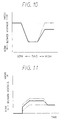
- FIG. 11 illustrates the change in the blower voltage with the time passage when the rapid heating is performed to heat the inside of the passenger compartment.
- the solid line indicates the blower voltage controlled in the steps 170 and 190
- the one-dotted chain line indicates the blower voltage controlled in the steps 180 and 190
- the two-dotted chain line indicates the blower voltage controlled with the air amount setting switch 53 manually set and fixed to "Lo" mode.
- either one of the steps 140 to 160 may be eliminated. That is, by performing the steps 170 and 190 in the outside air introduction mode and performing the steps 180 and 190 in the inside air circulation mode, it is possible to reduce the consumed electric power of the electric motor 30 and to prevent the efficiency of the refrigerating cycle 20 from being deteriorated.
- the high pressure is set with the temperature setting lever 56.
- the rotational speed of the compressor may be set with the temperature setting lever 56 to the set value.
- the air mode is set to the inside air introduction mode
- the low-temperature outside air is introduced into the intake side of the indoor heating heat exchanger 12 and thereby the temperature of the air blown into the passenger compartment is slightly lowered.
- the reduction margin of the blowing air temperature can be reduced or eliminated.
- the heat exchangers 11 and 12 of the refrigerating cycle 20 may be replaced with electric heaters.
- the air conditioning apparatus is used for electric vehicles in each of the embodiments described above, however, the air conditioning apparatus may also be used for rooms in a house or a building.
Claims (19)
- Appareil de climatisation pour un véhicule possédant un compartiment pour passagers, ledit appareil de climatisation comprenant :un coffret possédant un passage (21) pour l'air dans lequel sont constituées une entrée d'air intérieur (5) pour l'aspiration de l'air et une entrée d'air extérieur (6) pour l'aspiration d'air extérieur à une extrémité et une sortie d'air (14 à 16) destinée à souffler l'air dans un compartiment pour passagers à l'autre extrémité ;un moyen d'ouverture et de fermeture (7) pour l'ouverture et la fermeture sélectives de ladite entrée d'air (5) et de ladite entrée d'air extérieur (6) d'une manière telle qu'on puisse choisir entre un mode de circulation de l'air intérieur dans lequel ladite entrée d'air intérieur (5) est ouverte et ladite entrée d'air extérieur (6) est fermée ou un mode d'introduction de l'air extérieur dans lequel ladite entrée d'air extérieur (6) est ouverte et ladite entrée d'air intérieur (5) est fermée ;un échangeur de chaleur (11, 12) placé dans ledit passage d'air (2) pour l'échange de chaleur avec l'air dans ledit passage d'air (2) ;un moyen de soufflage (4) de l'air pour la génération d'un écoulement d'air dans le passage d'air (2), de ladite entrée d'air (5) ou de ladite entrée d'air extérieur (6) vers ladite sortie d'air (14 à 16) ;un moyen de détermination (S130) du mode de commutation entre air intérieur et air extérieur pour déterminer si ledit moyen d'ouverture et fermeture (7) des entrées d'air se trouve dans ledit mode de circulation de l'air intérieur ou dans ledit mode d'introduction de l'air extérieur, caractérisé parun premier moyen de commande (S180, S190) de l'écoulement d'air pour la commande dudit moyen de soufflage (4) d'air d'une manière telle qu'une quantité d'air issue dudit moyen de soufflage (4) d'air soit fixée à une première quantité d'air quand ledit mode de circulation de l'air intérieur est déterminé par ledit moyen de détermination (S130) de la commutation entre air intérieur et air extérieur ; etun second moyen de commande (S170, S190) de l'écoulement d'air pour la commande dudit moyen de soufflage d'air (4) d'une manière telle que ladite quantité d'air issue dudit moyen de soufflage d'air (4) soit fixée à une seconde quantité d'air inférieure à ladite première quantité d'air quand ledit mode de circulation de l'air extérieur est déterminé par ledit moyen de détermination (S130) de la commutation entre air intérieur et air extérieur, dans lequel la capacité dudit échangeur de chaleur (11, 12) est commandée électriquement.
- Appareil de climatisation selon la revendication 1, dans lequel ladite première quantité d'air est une quantité d'air normale fixée pour une climatisation normale.
- Appareil de climatisation selon l'une quelconque des revendications 1 et 2,
dans lequel ledit premier moyen de commande (S180, S190) de l'écoulement d'air comprend un premier moyen de détermination (S180) de la quantité d'air pour la détermination d'une quantité d'air issue dudit moyen de soufflage (4) d'air en tant que ladite première quantité d'air quand ledit mode de circulation de l'air intérieur est déterminé par ledit moyen de détermination (S130) de la commutation entre air intérieur et air extérieur d'une manière telle que la quantité d'air issue dudit moyen de soufflage (4) d'air soit fixée à ladite première quantité ; et
dans lequel ledit second moyen de commande (S170, S190) de l'écoulement d'air comprend un second moyen de détermination (S170) de la quantité d'air pour la détermination d'une quantité d'air issue dudit moyen de soufflage (4) d'air en tant que ladite seconde quantité d'air quand ledit mode de circulation de l'air extérieur est déterminé par ledit moyen de détermination (S130) de la commutation entre air intérieur et air extérieur d'une manière telle que la quantité d'air issue dudit moyen de soufflage (4) d'air soit fixée à ladite seconde quantité. - Appareil de climatisation selon la revendication 3, dans lequel ledit second moyen de détermination (S170) de la quantité d'air détermine ladite seconde quantité d'air d'une manière telle qu'au moins la quantité d'air maximale de ladite seconde quantité d'air soit inférieure à ladite quantité d'air maximale de ladite première quantité d'air.
- Appareil de climatisation selon l'une quelconque des revendications 1 à 4, comprenant en outre :dans lequel ledit moyen de soufflage (4) d'air est commandé par ledit second moyen de commande (S170, S190) de l'écoulement d'air quand ledit mode de circulation de l'air extérieur est déterminé par ledit moyen de détermination (S130) de la commutation entre air intérieur et air extérieur et quand est déterminée une condition de réduction de ladite puissance électrique par ledit moyen de détermination (S140 à 160) d'une condition de réduction de puissance électrique.un moyen de détermination (S140 à 160) d'une condition de réduction de puissance électrique pour déterminer si la puissance électrique pour le réglage de ladite capacité dudit échangeur de chaleur (11, 12) doit être réduite ou non,
- Appareil de climatisation selon la revendication 5, dans lequel ledit moyen de détermination (S140 à 160) d'une condition de réduction de puissance électrique comprend un moyen de détermination (S140) du mode de fonctionnement pour déterminer si ledit échangeur de chaleur (11, 12) est ou non en mode de fonctionnement avec chauffage dans le but de réchauffer l'air dans ledit passage d'air, et si ladite puissance électrique est réduite quand ledit mode de fonctionnement avec chauffage est déterminé par ledit moyen de détermination (S140) du mode de fonctionnement.
- Appareil de climatisation selon l'une quelconque des revendications 5 et 6, comprenant en outre :dans lequel ledit moyen de détermination (S140 à 160) d'une condition de réduction de puissance électrique comprend un moyen de détection (S150) de la température de l'air extérieur pour déterminer si ladite température de l'air extérieur détectée par ledit moyen de détection (41) de la température de l'air extérieur est ou non égale ou inférieure à une température prédéterminée de l'air extérieur, et si ladite puissance électrique est réduite quand ladite température de l'air extérieur détectée par ledit moyen de détection (41) de la température de l'air extérieur est égale ou inférieure à ladite température prédéterminée de l'air extérieur.un moyen de détection (41) de la température de l'air extérieur pour la détection de la température dudit air extérieur ;
- Appareil de climatisation selon l'une quelconque des revendications 5 à 7, comprenant en outre :un moyen d'entrée (57) d'une instruction d'économie d'énergie électrique pour l'introduction d'une instruction d'économie d'énergie électrique réglant ladite capacité dudit échangeur de chaleur (11, 12), ledit moyen de détermination (S140 à 160) d'une condition de réduction de la puissance électrique comprenant un moyen de détermination (57) d'une instruction d'économie d'énergie électrique pour déterminer si ladite instruction d'économie d'énergie électrique a été ou non introduite dans ledit moyen d'entrée (57) d'une instruction d'économie d'énergie électrique, et si ladite puissance électrique est réduite quand ladite instruction d'économie d'énergie électrique a été ou non introduite dans ledit moyen d'entrée (57) d'une instruction d'économie d'énergie électrique.
- Appareil de climatisation selon l'une quelconque des revendications 1 à 8, comprenant en outre :un compresseur (21) pour la constitution d'un cycle de réfrigération (20) avec ledit échangeur de chaleur (11, 12), et ledit compresseur (21) étant entraíné par un moteur électrique (30).
- Appareil de climatisation selon la revendication 9, dans lequel ledit cycle de réfrigération (20) est un cycle de réfrigération du type à pompe à chaleur.
- Appareil de climatisation selon l'une quelconque des revendications 1 à 10, dans lequel ledit appareil de climatisation pour automobiles est destiné aux véhicules électriques.
- Appareil de climatisation selon la revendication 1 pour la climatisation dans une pièce, ledit appareil de climatisation comprenant en outre :un moyen de modification (S170, S190) de la quantité d'air pour la commande dudit moyen de soufflage d'air d'une manière telle que ladite première quantité d'air est modifiée en une seconde quantité d'air inférieure à ladite première quantité d'air quand ledit mode d'introduction d'air extérieur est déterminé par ledit moyen de détermination (S130) du mode de commutation entre air intérieur et air extérieur.
- Appareil de climatisation selon la revendication 12, dans lequel ladite quantité d'air issue dudit moyen de soufflage (4) d'air est modifiée sélectivement pas à pas, indépendamment dudit moyen de modification (S170, S190) de la quantité d'air.
- Appareil de climatisation selon la revendication 12, dans lequel ledit moyen de modification (S170, S190) de la quantité d'air commande ledit moyen de soufflage (4) d'air d'une manière telle que ladite première quantité d'air n'est modifiée en ladite seconde quantité d'air que quand ladite première quantité d'air issue dudit moyen de soufflage (4) d'air est à sa valeur maximale.
- Appareil de climatisation selon l'une quelconque des revendications 13 et 14, comprenant en outre :dans lequel ledit moyen de modification de la quantité d'air (S170, S190) commande ledit moyen de soufflage d'air d'une manière telle que ladite première quantité d'air n'est modifiée en ladite seconde quantité d'air que quand ladite température extérieure détectée par ledit moyen de détermination (41) est égale ou inférieure à ladite température prédéterminée de l'air extérieur.un moyen de détection (41) de la température de l'air extérieur pour la détection de la température dudit air extérieur ;
- Appareil de climatisation selon l'une quelconque des revendications 13 à 15, comprenant en outre :dans lequel ledit moyen de détermination (S140, S160) d'une condition de réduction de puissance électrique comprend un moyen de détermination (S160) d'une instruction d'économie d'énergie électrique pour l'introduction d'une instruction d'économie d'énergie électrique pour déterminer si ladite instruction d'économie d'énergie électrique a été ou non introduite dans ledit moyen d'entrée (57) d'une instruction d'économie d'énergie électrique,un moyen de détermination (S140 à 160) d'une condition de réduction de puissance électrique pour déterminer si la puissance électrique pour le réglage de ladite capacité dudit échangeur de chaleur (11, 12) doit être réduite ou non ;un moyen d'entrée (57) d'une instruction d'économie d'énergie électrique pour l'introduction d'une instruction d'économie d'énergie électrique réglant ladite capacité dudit échangeur de chaleur (11, 12),
ledit moyen de modification de la quantité d'air commandant ledit moyen de soufflage d'air d'une manière telle que ladite première quantité d'air n'est modifiée en ladite seconde quantité d'air que quand ladite instruction d'économie d'énergie électrique a été introduite par ledit moyen de détermination (S160) d'une instruction d'économie d'énergie électrique (S140 à 160). - Appareil de climatisation selon l'une quelconque des revendications 13 à 16, comprenant en outre :un compresseur (21) pour la constitution d'un cycle de réfrigération (20) avec ledit échangeur de chaleur, et ledit compresseur (21) étant entraíné par un moteur électrique (30).
- Appareil de climatisation selon la revendication 1 pour la climatisation dans une pièce, ledit appareil de climatisation comprenant en outre :une unité de climatisation placée dans ledit passage d'air (2) pour la climatisation de l'air dans ledit passage d'air (2), ladite unité de climatisation comprenant un compresseur (21) et un échangeur de chaleur (11, 12) afin de constituer un cycle de réfrigération (20), la capacité de ladite unité de climatisation étant commandée électriquement, ledit moyen de soufflage (4) étant commandé électriquement.
- Appareil de climatisation selon la revendication 18, dans lequel ladite quantité d'air issue dudit moyen de soufflage (4) d'air est modifiée sélectivement pas à pas, indépendamment dudit moyen de modification (S170, S190) de la quantité d'air.
Applications Claiming Priority (3)
| Application Number | Priority Date | Filing Date | Title |
|---|---|---|---|
| JP139704/95 | 1995-06-06 | ||
| JP13970495A JP3596090B2 (ja) | 1995-06-06 | 1995-06-06 | 車両用空調装置 |
| JP13970495 | 1995-06-06 |
Publications (3)
| Publication Number | Publication Date |
|---|---|
| EP0747247A2 EP0747247A2 (fr) | 1996-12-11 |
| EP0747247A3 EP0747247A3 (fr) | 1999-03-03 |
| EP0747247B1 true EP0747247B1 (fr) | 2002-04-24 |
Family
ID=15251482
Family Applications (1)
| Application Number | Title | Priority Date | Filing Date |
|---|---|---|---|
| EP96108930A Expired - Lifetime EP0747247B1 (fr) | 1995-06-06 | 1996-06-04 | Dispositif de climatisation |
Country Status (4)
| Country | Link |
|---|---|
| US (1) | US5706667A (fr) |
| EP (1) | EP0747247B1 (fr) |
| JP (1) | JP3596090B2 (fr) |
| DE (1) | DE69620823T2 (fr) |
Families Citing this family (21)
| Publication number | Priority date | Publication date | Assignee | Title |
|---|---|---|---|---|
| JPH09123738A (ja) * | 1995-10-31 | 1997-05-13 | Denso Corp | 空気流路調節装置 |
| DE69734308T2 (de) | 1996-11-15 | 2006-06-14 | Calsonic Kansei Corp | Fahrzeugklimaanlage |
| US6105666A (en) * | 1997-10-30 | 2000-08-22 | Calsonic Corporation | Vehicular air conditioning apparatus |
| US6370903B1 (en) | 2001-03-14 | 2002-04-16 | Visteon Global Technologies, Inc. | Heat-pump type air conditioning and heating system for fuel cell vehicles |
| JP4597415B2 (ja) * | 2001-04-09 | 2010-12-15 | 株式会社日本クライメイトシステムズ | 車両用空調装置 |
| JP2003025832A (ja) * | 2001-07-12 | 2003-01-29 | Denso Corp | 車両用空調装置 |
| JP4459046B2 (ja) * | 2004-12-27 | 2010-04-28 | トヨタ自動車株式会社 | 自動車およびその制御方法 |
| KR101099899B1 (ko) * | 2005-02-18 | 2011-12-28 | 스미토모 덴키 고교 가부시키가이샤 | 극저온 케이블의 순환 냉각 시스템 |
| JP5195702B2 (ja) * | 2009-09-21 | 2013-05-15 | 株式会社デンソー | 車両用空調装置 |
| US8508182B2 (en) * | 2009-11-09 | 2013-08-13 | International Business Machines Corporation | Electrically connecting blower to power supply stage providing higher voltage |
| JP5617507B2 (ja) * | 2010-10-01 | 2014-11-05 | 株式会社デンソー | 車両用空調装置 |
| US10183547B2 (en) * | 2012-05-24 | 2019-01-22 | Honda Motor Co., Ltd | Idle stop and heater control system and method for a vehicle |
| JP6052028B2 (ja) * | 2013-04-03 | 2016-12-27 | 株式会社デンソー | モータ制御装置 |
| JP6015607B2 (ja) * | 2013-09-18 | 2016-10-26 | 株式会社デンソー | 車両用空調ユニット |
| JP6207958B2 (ja) * | 2013-10-07 | 2017-10-04 | サンデンホールディングス株式会社 | 車両用空気調和装置 |
| WO2017187668A1 (fr) * | 2016-04-25 | 2017-11-02 | 株式会社デンソー | Dispositif de commande de climatisation et système de commande de véhicule |
| US10369887B2 (en) * | 2017-07-21 | 2019-08-06 | Ford Global Technologies, Llc | Inverter system controller power optimization |
| US11413932B2 (en) * | 2017-10-12 | 2022-08-16 | Ford Global Technologies, Llc | Blower motor operation |
| US10717339B2 (en) * | 2018-03-21 | 2020-07-21 | Toyota Motor Engineering & Manufacturing North America, Inc. | Start and stop blower map based on sunload to improve fuel economy |
| US11491846B2 (en) * | 2018-04-12 | 2022-11-08 | Ford Global Technologies, Llc | Blower motor operation for an electrified vehicle |
| DE102018127108B4 (de) * | 2018-10-30 | 2021-04-22 | Hanon Systems | Vorrichtungen für ein Klimatisierungssystem eines Kraftfahrzeugs sowie ein Verfahren zum Betreiben der Vorrichtungen |
Family Cites Families (12)
| Publication number | Priority date | Publication date | Assignee | Title |
|---|---|---|---|---|
| JPS5225341A (en) * | 1975-08-20 | 1977-02-25 | Hitachi Ltd | Heat pump-type air conditioning system |
| JPS6085012A (ja) * | 1983-10-17 | 1985-05-14 | Diesel Kiki Co Ltd | 車両用空気調和装置 |
| JPS60143116A (ja) * | 1983-12-29 | 1985-07-29 | Nissan Motor Co Ltd | 車両の空調用フアンモ−タ制御回路 |
| JPS6441415A (en) * | 1987-08-03 | 1989-02-13 | Mazda Motor | Control device for vehicular air conditioner |
| JPH0761763B2 (ja) * | 1987-12-21 | 1995-07-05 | 日産自動車株式会社 | 自動車用空調装置 |
| KR930009384B1 (ko) * | 1989-12-19 | 1993-10-02 | 마쯔다 가부시기가이샤 | 자동차용 공기조화장치 |
| JPH0563922A (ja) * | 1991-09-04 | 1993-03-12 | Nec Corp | イメージスキヤナ制御回路 |
| FR2687955B1 (fr) * | 1992-02-28 | 1995-05-05 | Renault | Dispositif d'admission de l'air de chauffage et de ventilation avec recyclage de l'air de l'habitacle d'un vehicule. |
| JP2990989B2 (ja) * | 1993-03-04 | 1999-12-13 | 松下電器産業株式会社 | 車両用ヒートポンプ式空調装置 |
| JP3201055B2 (ja) * | 1993-03-10 | 2001-08-20 | 日産自動車株式会社 | 空調装置を備えた車両 |
| JPH0717241A (ja) * | 1993-06-30 | 1995-01-20 | Nissan Motor Co Ltd | エンジン補機の回転数制御装置 |
| JPH07117452A (ja) * | 1993-10-27 | 1995-05-09 | Sanden Corp | 車両用空気調和装置の風量制御装置 |
-
1995
- 1995-06-06 JP JP13970495A patent/JP3596090B2/ja not_active Expired - Lifetime
-
1996
- 1996-06-04 EP EP96108930A patent/EP0747247B1/fr not_active Expired - Lifetime
- 1996-06-04 DE DE69620823T patent/DE69620823T2/de not_active Expired - Lifetime
- 1996-06-04 US US08/658,118 patent/US5706667A/en not_active Expired - Lifetime
Also Published As
| Publication number | Publication date |
|---|---|
| JPH08332829A (ja) | 1996-12-17 |
| DE69620823D1 (de) | 2002-05-29 |
| EP0747247A2 (fr) | 1996-12-11 |
| US5706667A (en) | 1998-01-13 |
| JP3596090B2 (ja) | 2004-12-02 |
| EP0747247A3 (fr) | 1999-03-03 |
| DE69620823T2 (de) | 2002-11-28 |
Similar Documents
| Publication | Publication Date | Title |
|---|---|---|
| EP0747247B1 (fr) | Dispositif de climatisation | |
| JP3463303B2 (ja) | 車両用ヒートポンプ式冷暖房装置 | |
| US6311763B1 (en) | Vehicle air conditioner | |
| US20060225875A1 (en) | Air conditioning apparatus for vehicle | |
| EP0747248A2 (fr) | Dispositif de climatisation | |
| JP2916829B2 (ja) | 車両用空調装置の騒音低減装置 | |
| JP3085329B2 (ja) | 車両用空気調和装置 | |
| JPS6015217A (ja) | 車両用空気調和装置 | |
| JPH10915A (ja) | 車両用空調装置 | |
| KR100205235B1 (ko) | 자동차 자동온도 제어 시스템 및 방법 | |
| KR100928000B1 (ko) | 자동차용 공기조화장치의 난방 제어방법 | |
| KR19980050724A (ko) | 자동차 시트 공조장치 | |
| JP2003159930A (ja) | 車両用空調装置 | |
| JP3633035B2 (ja) | 空調装置 | |
| JP2564906B2 (ja) | 自動車用空気調和装置 | |
| JPH08332828A (ja) | 車両用空調装置 | |
| KR101177938B1 (ko) | 차량용 공조장치 제어방법 | |
| KR100188033B1 (ko) | 자동차 배출구 자동 제어 장치 및 방법 | |
| JPH06206426A (ja) | 車両用ヒートポンプ式空調装置 | |
| KR19990005847U (ko) | 자동차 공조장치의 내/외기모드 자동제어장치 | |
| JPH0818491B2 (ja) | 自動車用空気調和装置 | |
| JPH06255343A (ja) | 車両用空調装置 | |
| JPH0840048A (ja) | 車両用空調装置のインテークドア制御装置 | |
| JPH06255340A (ja) | 電気自動車用空気調和装置 | |
| JPH06227246A (ja) | 車両用ヒートポンプ式冷暖房装置 |
Legal Events
| Date | Code | Title | Description |
|---|---|---|---|
| PUAI | Public reference made under article 153(3) epc to a published international application that has entered the european phase |
Free format text: ORIGINAL CODE: 0009012 |
|
| AK | Designated contracting states |
Kind code of ref document: A2 Designated state(s): DE FR GB |
|
| RAP1 | Party data changed (applicant data changed or rights of an application transferred) |
Owner name: DENSO CORPORATION |
|
| PUAL | Search report despatched |
Free format text: ORIGINAL CODE: 0009013 |
|
| AK | Designated contracting states |
Kind code of ref document: A3 Designated state(s): DE FR GB |
|
| 17P | Request for examination filed |
Effective date: 19990518 |
|
| 17Q | First examination report despatched |
Effective date: 20001204 |
|
| GRAG | Despatch of communication of intention to grant |
Free format text: ORIGINAL CODE: EPIDOS AGRA |
|
| GRAG | Despatch of communication of intention to grant |
Free format text: ORIGINAL CODE: EPIDOS AGRA |
|
| GRAH | Despatch of communication of intention to grant a patent |
Free format text: ORIGINAL CODE: EPIDOS IGRA |
|
| GRAH | Despatch of communication of intention to grant a patent |
Free format text: ORIGINAL CODE: EPIDOS IGRA |
|
| REG | Reference to a national code |
Ref country code: GB Ref legal event code: IF02 |
|
| GRAA | (expected) grant |
Free format text: ORIGINAL CODE: 0009210 |
|
| AK | Designated contracting states |
Kind code of ref document: B1 Designated state(s): DE FR GB |
|
| REG | Reference to a national code |
Ref country code: GB Ref legal event code: FG4D |
|
| REF | Corresponds to: |
Ref document number: 69620823 Country of ref document: DE Date of ref document: 20020529 |
|
| ET | Fr: translation filed | ||
| PLBE | No opposition filed within time limit |
Free format text: ORIGINAL CODE: 0009261 |
|
| STAA | Information on the status of an ep patent application or granted ep patent |
Free format text: STATUS: NO OPPOSITION FILED WITHIN TIME LIMIT |
|
| 26N | No opposition filed |
Effective date: 20030127 |
|
| PGFP | Annual fee paid to national office [announced via postgrant information from national office to epo] |
Ref country code: FR Payment date: 20110621 Year of fee payment: 16 |
|
| PGFP | Annual fee paid to national office [announced via postgrant information from national office to epo] |
Ref country code: GB Payment date: 20110601 Year of fee payment: 16 |
|
| PGFP | Annual fee paid to national office [announced via postgrant information from national office to epo] |
Ref country code: DE Payment date: 20110601 Year of fee payment: 16 |
|
| GBPC | Gb: european patent ceased through non-payment of renewal fee |
Effective date: 20120604 |
|
| REG | Reference to a national code |
Ref country code: FR Ref legal event code: ST Effective date: 20130228 |
|
| REG | Reference to a national code |
Ref country code: DE Ref legal event code: R119 Ref document number: 69620823 Country of ref document: DE Effective date: 20130101 |
|
| PG25 | Lapsed in a contracting state [announced via postgrant information from national office to epo] |
Ref country code: GB Free format text: LAPSE BECAUSE OF NON-PAYMENT OF DUE FEES Effective date: 20120604 Ref country code: DE Free format text: LAPSE BECAUSE OF NON-PAYMENT OF DUE FEES Effective date: 20130101 Ref country code: FR Free format text: LAPSE BECAUSE OF NON-PAYMENT OF DUE FEES Effective date: 20120702 |