EP0743502B1 - Verfahren und Vorrichtung zur Umlaborierung von Trägergeschossen - Google Patents
Verfahren und Vorrichtung zur Umlaborierung von Trägergeschossen Download PDFInfo
- Publication number
- EP0743502B1 EP0743502B1 EP96107347A EP96107347A EP0743502B1 EP 0743502 B1 EP0743502 B1 EP 0743502B1 EP 96107347 A EP96107347 A EP 96107347A EP 96107347 A EP96107347 A EP 96107347A EP 0743502 B1 EP0743502 B1 EP 0743502B1
- Authority
- EP
- European Patent Office
- Prior art keywords
- bomblet
- layer
- projectile
- bomblets
- lid
- Prior art date
- Legal status (The legal status is an assumption and is not a legal conclusion. Google has not performed a legal analysis and makes no representation as to the accuracy of the status listed.)
- Expired - Lifetime
Links
- 238000000034 method Methods 0.000 title claims description 25
- 239000002360 explosive Substances 0.000 claims description 7
- 238000005474 detonation Methods 0.000 claims description 3
- 239000004429 Calibre Substances 0.000 claims 4
- 230000003213 activating effect Effects 0.000 claims 1
- 230000014759 maintenance of location Effects 0.000 claims 1
- 238000009877 rendering Methods 0.000 claims 1
- 229910052751 metal Inorganic materials 0.000 description 5
- 239000002184 metal Substances 0.000 description 5
- 230000007246 mechanism Effects 0.000 description 4
- 230000000694 effects Effects 0.000 description 3
- LFQSCWFLJHTTHZ-UHFFFAOYSA-N Ethanol Chemical compound CCO LFQSCWFLJHTTHZ-UHFFFAOYSA-N 0.000 description 1
- 206010041662 Splinter Diseases 0.000 description 1
- 239000000853 adhesive Substances 0.000 description 1
- 230000001070 adhesive effect Effects 0.000 description 1
- 229910052782 aluminium Inorganic materials 0.000 description 1
- XAGFODPZIPBFFR-UHFFFAOYSA-N aluminium Chemical compound [Al] XAGFODPZIPBFFR-UHFFFAOYSA-N 0.000 description 1
- 230000015572 biosynthetic process Effects 0.000 description 1
- 238000010438 heat treatment Methods 0.000 description 1
- 238000003801 milling Methods 0.000 description 1
- 239000000203 mixture Substances 0.000 description 1
- 238000002360 preparation method Methods 0.000 description 1
- 230000035945 sensitivity Effects 0.000 description 1
- 239000002904 solvent Substances 0.000 description 1
- 239000002023 wood Substances 0.000 description 1
Images


Classifications
-
- F—MECHANICAL ENGINEERING; LIGHTING; HEATING; WEAPONS; BLASTING
- F42—AMMUNITION; BLASTING
- F42B—EXPLOSIVE CHARGES, e.g. FOR BLASTING, FIREWORKS, AMMUNITION
- F42B33/00—Manufacture of ammunition; Dismantling of ammunition; Apparatus therefor
- F42B33/06—Dismantling fuzes, cartridges, projectiles, missiles, rockets or bombs
-
- F—MECHANICAL ENGINEERING; LIGHTING; HEATING; WEAPONS; BLASTING
- F42—AMMUNITION; BLASTING
- F42B—EXPLOSIVE CHARGES, e.g. FOR BLASTING, FIREWORKS, AMMUNITION
- F42B33/00—Manufacture of ammunition; Dismantling of ammunition; Apparatus therefor
- F42B33/001—Devices or processes for assembling ammunition, cartridges or cartridge elements from parts
Definitions
- the present invention relates to a method and a Device for the re-laboratoryization of floors, which one Variety of bomblets individually lockable against detonation one or more layers arranged, in which the Bomblets from a first floor to be disassembled Caliber in a second floor to be put together Caliber are brought, the floor to be disassembled is first prepared so that a first bomblet layer exposed.
- Bomblet projectiles are artillery shells that a load from submunition, the daughter floors or Bomblets, wear. When in use, these bomblets are over an ejection charge initiated by the time fuse from the Projectile sleeve ejected. This usually happens on the bottom side, where predetermined breaking points of the grenade base attachment must be overcome.
- the bomblets, their mechanisms of action Splinter formation and shaped charge effect are solved automatically from their association. You are with one each equipped its own detonator, which by swirl and aerodynamic Action after releasing from the bandage is released.
- Bomblet detonators usually have an ignition system, at which an inert mass provides the necessary initial energy. The safe function is sufficient rapid deceleration of the bomblet on impact on a goal ahead, especially with soft and yielding Structures such as snow, wood or vegetation, is not necessarily given. To ensure functional reliability to ensure that bomb detonators have highly sensitive ignition elements.
- the first bomblet layer in Attachment to a first according to the situation pattern of the Designed bomblets of the floor to be disassembled Bring the transport lid and hold it pneumatically will, under the bomblet ply after it comes out of the bullet case is removed, a bottom cover is brought, which is releasably attached the first transport cover is attached, the detonator each Bomblets is backed up, the Bomblets are singled out Bomblets at least partially on a second accordingly the location pattern of the bomblets of the floor to be assembled designed transport lid and arranged there pneumatically be held, the bottom cover is removed, the bomblet layer is lowered into the shell of the second floor and repeating the above steps so many times until either the last bomblet layer from the first Storey removed or a top bomblet layer in the second Projectile is used.
- each of the transport covers an opening is provided for each bomblet, because then the possibility opens up through these openings To provide Bomblet with a locking pin so that its Ignition mechanism is blocked.
- the Transport lid is turned through 180 ° as soon as the bomblet layer is adhered to.
- the process of re-processing bomblet bullets can are advantageously further developed in that for Repackaging storeys not required Bomblets are disposed of.
- the detonator that activates the bomblet is activated Scale housing blasted off the shaped charge funnel fixing flare is milled out, the explosives removed, the ignition amplifier is ejected, the bomblet housing is washed out and eventually explosives, Ignition amplifier and detonator burned.
- a facility for the re-laboratoryization of floors that are used for Implementation of the method according to the present invention is suitable, is characterized by at least a first Transport cover with a plant area for a bomblet layer according to a first location pattern in the one to be disarmed Storey, at least a second transport cover with one Investment area for a bomblet layer according to a second layer pattern on the floor to be put together, at least one Bottom cover, which is detachable on the first or second Transport cover is to be fastened in such a way that the bomblet layer is firmly held between the transport cover and the base cover, and a device for at least temporarily holding the Bomblet layer in contact with the respective transport cover.
- the transport cover has Openings through which a vacuum or vacuum is applied the investment area can be abandoned.
- the negative pressure or that Vacuum is applied by a suction manipulator, which the device for at least temporarily holding the Form the bomblet layer in contact with the respective transport cover can.
- the transport cover for each bomblet is also advantageous a nest of form, which is formed by a bombardment of the bomblet in the is to be closed essentially vacuum-tight, being in each Form nest one of the openings opens.
- Bomblet projectiles often also as grenade projectiles inscribed, have bomblets in layers in a shell arranged on, the bottom layer of the bomblets for securing bandages with metal bowls of the same internal configuration of a bomblet.
- the bullet head is screwed to the shell. This screw connection is usually additionally secured by an adhesive.
- the mouth hole of the projectile head are the mouth hole bushing with Ejection charge used. When it comes to storage and transportation Lifting ring locking screw screwed into the mouth thread.
- the lip screw To unlock such a projectile, the lip screw must be used solved and the ejection charge removed will. This is done in a conventional way and can be done with conventional means. This is followed by Unscrew the aluminum ogive. To threading Avoid heating the interface preferably at temperatures below 80 ° C. It it is advisable to loosen the thread first and into the Thread gap a mixture of a suitable solvent and Instilling alcohol. After a temporary exposure time the thread can be loosened completely.
- the base plate is now away. Because of the considerable effort to solve the Threaded connection must have a corresponding device have sufficient clamping and driving forces.
- the voltage must be circular in any case to ensure is that there are no forces on the deformation of the shell to act on the bomblet bandage.
- the opened floor is placed in a device brought, which makes it possible to layer the bomblet bandage in To move towards the bottom opening.
- the introduction of force happens via the expulsion plate attached to the head.
- the required expulsion force is preferably hydraulic applied, a low-frequency pulsing with low Amplitude makes it easier to overcome the initial one Resistance.
- the first bomblet layer is thus exposed on the ignition side.
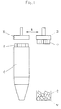
- FIG. 1 shows a projectile sleeve 10 that is still filled, from which the base plate is already removed.
- the metal bowls 12 for securing the first bomblet plate are exposed and can be removed by a suction lifter 30.
- the Suction lifter 30 is pivotable, as it is by the Double arrow A is indicated, such that the siphon Can place metal bowls 12 in a container 40.
- FIG 2 shows schematically the process for removing a Bombletlage 14 from the projectile sleeve 10
- a feed hydraulic system 50 is attached to the side of the projectile head, which the entire bomblet association towards the Bottom opening of the projectile sleeve 10 moves until the first Bombletlage 14 is exposed.
- From a magazine 60 for transport lids becomes a closer in connection with Figure 3 descriptive transport cover 20 removed and on a Suction manipulator 52 held.
- Suction manipulator 52 and transport cover 20 then drive over the first bomblet layer; you will be so far lowered that the first bomblet layer is in contact with the Transport cover 20 comes.
- the bomblets of the bomblet layer 14 are then pneumatic, with the help of the suction manipulator 52 the transport blanket 20 held.
- FIG. 3 shows a detailed representation of the bomblet layer 14 and the transport cover 20, such as a bandage protection for the Bombletlage 14 is reached.
- a mold cavity 22 is provided in the transport cover 20, in that the bomblet is to be used on the ignition side. Every nest of form 22 is to the side of the suction manipulator 52 Transport cover 20 provided with an opening 24 which on Mold cavity 22 is arranged such that through this opening 24th a locking pin for the ignition mechanism of a bomblet can be used.
- the suction manipulator 52 lies over a Seal 52 on the transport lid 20, wherein between Suction manipulator 52 and transport cover 20 one with all Holes 24 communicating space remains free.
- Bomblet layer 14 can thus together with the transport cover 20 of the Suction manipulator 52 can be removed from the projectile sleeve. Under the bomblet layer 14 there is a bottom cover 28 which by means of a locking clip 29 on a on the transport lid 20 provided approach 26 takes effect. The suction manipulator 52 can then be removed from the transport cover 20 so that the Holes 24 are exposed and through these holes 24 for each Bomblet the locking pin can be inserted. Transport cover 20 and bottom cover 28 can then safely from each other be separated so that the bomblet layer 14 is exposed and the Bomblets can be separated. The delaborating process for a bomblet layer is over.
- the process just described could happen so often be repeated until all the bomblet layers come out of the shell are removed.
- Filling an empty projectile sleeve, for example one other caliber, with the occasional bomblets in one second transport cover are used, which is basically has the same structure as the transport cover just described 20, with a mold cavity 22 for each bomblet Bore 24 is provided.
- the location pattern of the mold nests 22 and with it the Bomblets is chosen however so that it belongs to the Projectile sleeve of the projectile to be assembled is adapted.
- the isolated bomblets with safety pin are in such Transport cover that the different arrangement of the bomblets take into account, inserted and by attaching the Bottom cover secured so that the locking pin again can be removed.
- a suction manipulator 52 takes the transport cover again on, the bottom cover is removed and the bomblet layer becomes driven over the projectile sleeve to be equipped.
- the suction manipulator with the transport lid and the bomblet layer drained to the projectile sleeve.
- the appropriately set up Hydraulic feed 50 picks up the bomblet position from Transport cover is released so that the bomblet layer now lowered into the projectile sleeve with the aid of the hydraulic feed can be. The next bomblet layer can then be fed will.
- the delaborating and refitting steps are so frequent repeated until either the last bomblet layer from the first Storey removed or a top bomblet layer in the second Projectile is inserted.
- the described procedure enables safe dismantling sharp bomblets and re-laboring in Bullets of other calibers as well as safe disposal bomblets that are no longer required.
- the whole process is accessible to the robot controller so that the worker who Disassembly and restocking is secured.
Landscapes
- Engineering & Computer Science (AREA)
- Manufacturing & Machinery (AREA)
- General Engineering & Computer Science (AREA)
- Manipulator (AREA)
- Processing Of Solid Wastes (AREA)
- Toys (AREA)
- Load-Engaging Elements For Cranes (AREA)
Description
- Figur 1
- eine erste Station zur Umlaborierung von Geschossen zur Durchführung des Verfahrens gemäß der vorliegenden Erfindung;
- Figur 2
- eine zweite Station für die Umlaborierung von Geschossen gemäß dem Verfahren der vorliegenden Erfindung;
- Figur 3
- eine Detailansicht einer Bombletlage eines zu delaborierenden Geschosses und des Transportdeckels im Schnitt; und
- Figur 4
- eine Vorrichtung zum Entsorgen von Bomblets, die nicht zum Umlaborieren benötigt werden.
Claims (12)
- Verfahren zur Umlaborierung von Geschossen, welche eine Vielzahl von einzeln gegen Detonation sicherbaren Bomblets in einer oder mehreren Lagen (14) angeordnet enthalten, bei dem Bomblets aus einem zu delaborierenden Geschoß eines ersten Kalibers in ein zusammenzusetzendes Geschoß eines zweiten Kalibers gebracht werden, wobei das zu delaborierende Geschoß zunächst so vorbereitet wird, daß eine erste Bombletlage (14) freiliegt,
dadurch gekennzeichnet, daßa) die erste Bombletlage (14) in Anlage an einen ersten entsprechend dem Lagemuster der Bomblets des zu delaborierenden Geschosses gestalteten Transportdeckel (20) gebracht und an diesem pneumatisch gehalten wird,b) unter die Bombletlage (14) ein Bodendeckel (28) gebracht wird, welcher lösbar an dem ersten Transportdeckel (20) befestigt wird,c) der Zünder jedes Bomblets gesichert wird,d) die Bomblets vereinzelt werden,e) die Bomblets zumindest teilweise auf einem entsprechend dem Lagemuster der Bomblets des zusammenzusetzenden Geschosses gestalteten Transportdeckel angeordnet werden,f) die Bombletlage in die Geschoßhülse des zusammenzusetzenden Geschosses abgesenkt werden; undg) die Schritte a) bis f) so oft wiederholt werden, bis entweder die letzte Bombletlage aus dem zu delaborierenden Geschoß entfernt oder eine oberste Bombletlage in das zusammenzusetzende Geschoß eingesetzt ist. - Verfahren nach Anspruch 1, dadurch gekennzeichnet, daß vor dem Entfernen einer freiliegenden Bombletlage (14) aus dem zu delaborierenden Geschoß festgestellt wird, ob der Zünder jedes Bomblets gesichert ist.
- Verfahren nach Anspruch 1 oder 2, dadurch gekennzeichnet, daß das pneumatische Halten der Bombletlagen an dem ersten oder zweiten Transportdeckel durch ein an Öffnungen (24) des Transportdeckels (20) anliegendes Vakuum vorgenommen wird.
- Verfahren nach Anspruch 3, dadurch gekennzeichnet, daß an jedem der Transportdeckel (20) für jedes Bomblet eine Öffnung (24) vorgesehen ist.
- Verfahren nach Anspruch 4, dadurch gekennzeichnet, daß jede der Öffnungen (24) in dem jeweiligen Transportdeckel (20) so angeordnet ist, daß ein Bomblet durch diese Öffnung (24) mit einem Sicherungsstift zu versehen ist.
- Verfahren nach einem der Ansprüche 1 bis 5, dadurch gekennzeichnet, daß anschließend an den Schritt a) der Transportdeckel (20) um 180° gewendet wird.
- Verfahren nach einem der Ansprüche 1 bis 6, dadurch gekennzeichnet, daß für die Wiederbestückung zusammenzubauender Geschosse nicht benötigte Bomblets entsorgt werden.
- Verfahren nach Anspruch 7, dadurch gekennzeichnet, daß bei jedem Bombletdas den Detonator aktivierende Zundergehäuse (162) abgesprengt wird;die den Hohlladungstrichter (166) fixierende Bördelstelle (168) ausgefräst wird;der Sprengstoff (170) entfernt wird;der Zündverstärker (172) ausgestoßen wird;das Bombletgehäuse (160) ausgewaschen wird undSprengstoff (170), Zündverstärker (172) und Detonator verbrannt werden.
- Einrichtung zur Umlaborierung von Geschossen, welche eine Vielzahl von einzeln gegen Detonation sicherbaren Bomblets in einer oder mehreren Lagen (14) angeordnet enthalten, wobei Bomblets aus einem zu delaborierenden Geschoß eines ersten Kalibers in ein zusammenzusetzendes Geschoß eines zweiten Kalibers gebracht werden, insbesondere zur Durchführung des Verfahrens nach einem der vorangehenden Ansprüche,
gekennzeichnet durchmindestens einen ersten Transportdeckel (20), mit einem Anlagebereich für eine Bombletlage (14) nach einem ersten Lagemuster der Bomblets in dem zu delaborierenden Geschoß,mindestens einen zweiten Transportdeckel mit einem Anlagebereich für eine Bombletlage nach einem zweiten Lagemuster in dem zusammenzusetzenden Geschoß;mindestens einen Bodendeckel (28), der lösbar an dem/den ersten und zweiten Transportdeckel(n) (20) zu befestigen ist, derart, daß die Bombletlage (14) zwischen Transportdeckel (20) und Bodendeckel (28) fest gehalten ist; undeine Vorrichtung (52) zum zumindest zeitweiligen Halten der Bombletlage in Anlage an den jeweiligen Transportdeckel. - Einrichtung nach Anspruch 9, dadurch gekennzeichnet, daß der Transportdeckel (20) Öffnungen (24) aufweist, durch die ein Unterdruck oder Vakuum auf den Anlagebereich aufgebbar ist.
- Einrichtung nach Anspruch 9 oder 10, dadurch gekennzeichnet, daß der Transportdeckel (20) für jedes Bomblet ein Formnest (22) aufweist, das durch einen Anlagerand des Bomblets im wesentlichen vakuumdicht zu verschließen ist, wobei in jedes Formnest (22) eine der Öffnungen (24) mündet.
- Einrichtung nach einem der Ansprüche 9 bis 11, dadurch gekennzeichnet, daß die Öffnungen (24) so angeordnet sind, daß durch sie jeweils ein Sicherungsstift zur Sicherung des jeweiligen Bomblets geführt werden kann.
Applications Claiming Priority (2)
| Application Number | Priority Date | Filing Date | Title |
|---|---|---|---|
| DE19517760A DE19517760C2 (de) | 1995-05-15 | 1995-05-15 | Verfahren und Vorrichtung zur Umlaborierung von Geschossen |
| DE19517760 | 1995-05-15 |
Publications (2)
| Publication Number | Publication Date |
|---|---|
| EP0743502A1 EP0743502A1 (de) | 1996-11-20 |
| EP0743502B1 true EP0743502B1 (de) | 1998-03-25 |
Family
ID=7761927
Family Applications (1)
| Application Number | Title | Priority Date | Filing Date |
|---|---|---|---|
| EP96107347A Expired - Lifetime EP0743502B1 (de) | 1995-05-15 | 1996-05-07 | Verfahren und Vorrichtung zur Umlaborierung von Trägergeschossen |
Country Status (4)
| Country | Link |
|---|---|
| US (1) | US5789695A (de) |
| EP (1) | EP0743502B1 (de) |
| DE (2) | DE19517760C2 (de) |
| IL (1) | IL118257A (de) |
Families Citing this family (15)
| Publication number | Priority date | Publication date | Assignee | Title |
|---|---|---|---|---|
| DE19822090C2 (de) * | 1998-05-16 | 2002-05-02 | Diehl Stiftung & Co | Munition |
| DE10132175A1 (de) * | 2001-07-03 | 2003-01-23 | Rheinmetall W & M Gmbh | Verfahren zum Auswechseln eines Zündergehäuses |
| RU2267082C2 (ru) * | 2003-08-25 | 2005-12-27 | Смагин Николай Петрович | Способ расснаряжения боеприпасов |
| RU2267081C2 (ru) * | 2003-08-25 | 2005-12-27 | Смагин Николай Петрович | Способ выплавки взрывчатых веществ из боеприпасов |
| US6901835B1 (en) * | 2003-11-26 | 2005-06-07 | Day & Zimmerman, Inc. | Cone and charge extractor |
| DE102004034784B4 (de) * | 2004-07-09 | 2009-08-27 | Spreewerk Lübben GmbH | Verfahren und Vorrichtung zur Delaborierung von explosivstoffhaltigen Körpern |
| FR2894660B1 (fr) * | 2005-12-08 | 2010-07-30 | Giat Ind Sa | Procede de demilitarisation de munitions |
| IL172589A (en) * | 2005-12-14 | 2010-11-30 | Israel Military Ind | Method of converting a cluster bomb into a unitary bomb |
| US8220395B1 (en) * | 2010-12-22 | 2012-07-17 | The United States Of America As Represented By The Secretary Of The Army | Method of converting bomblet to gun-launched grenade |
| GB201217580D0 (en) * | 2012-10-02 | 2012-11-14 | Reid John N | Disposal of munitions |
| TWI498521B (zh) * | 2012-12-19 | 2015-09-01 | Nat Inst Chung Shan Science & Technology | Ammunition Refurbishment System and Its Method |
| USD803342S1 (en) * | 2016-04-04 | 2017-11-21 | Frank Goff | Anvil plate for use with an impact bullet puller |
| US10508892B1 (en) * | 2016-08-15 | 2019-12-17 | The United States Of America As Represented By The Secretary Of The Navy | Distributed fuze architecture for highly reliable submunitions |
| US12502786B2 (en) * | 2019-01-10 | 2025-12-23 | Cybernet Systems Corp. | Robotic system for demiliterizing munitions |
| CN113834389B (zh) * | 2021-09-30 | 2023-07-04 | 重庆航天工业有限公司 | 一种弹体后处理设备 |
Family Cites Families (11)
| Publication number | Priority date | Publication date | Assignee | Title |
|---|---|---|---|---|
| US3229561A (en) * | 1964-09-16 | 1966-01-18 | Thomas D Jones | Method and apparatus for assembling and disassembling various artillery and mortar shells |
| US4253375A (en) * | 1979-08-14 | 1981-03-03 | The United States Of America As Represented By The Secretary Of The Army | Loading head |
| DE3333312A1 (de) * | 1983-09-15 | 1985-04-04 | Rheinmetall GmbH, 4000 Düsseldorf | Zuender fuer ein tochtergeschoss |
| DE3434878A1 (de) * | 1984-09-22 | 1986-04-03 | Rheinmetall GmbH, 4000 Düsseldorf | Lastengeschoss |
| US4750423A (en) * | 1986-01-31 | 1988-06-14 | Loral Corporation | Method and system for dispensing sub-units to achieve a selected target impact pattern |
| DE3732744A1 (de) * | 1987-09-29 | 1989-04-06 | Rheinmetall Gmbh | Bomblettraegergeschoss mit bomblets |
| DE3844974C2 (de) * | 1988-12-10 | 1999-09-02 | Rheinmetall Ind Ag | Übungs-Bomblet |
| DE3841908A1 (de) * | 1988-12-13 | 1990-07-05 | Rheinmetall Gmbh | Drallstabilisiertes bomblettraegergeschoss mit beim ausstoss abstuetzbaren bomblets |
| DE3841907A1 (de) * | 1988-12-13 | 1990-06-28 | Rheinmetall Gmbh | Drallstabilisiertes bomblettraegergeschoss mit einem die bombletsaeulen abstuetzenden aufsatz |
| FR2668255B1 (fr) * | 1990-10-19 | 1994-08-26 | Thomson Brandt Armements | Dispositif de solidarisation de grenades a l'interieur d'un projectile en rotation autour de son axe longitudinal. |
| US5353676A (en) * | 1993-12-27 | 1994-10-11 | The United States Of America As Represented By The Secretary Of The Army | Apparatus and method for remote disassembly of failed high explosive type mine |
-
1995
- 1995-05-15 DE DE19517760A patent/DE19517760C2/de not_active Expired - Fee Related
-
1996
- 1996-05-07 DE DE59600121T patent/DE59600121D1/de not_active Expired - Lifetime
- 1996-05-07 EP EP96107347A patent/EP0743502B1/de not_active Expired - Lifetime
- 1996-05-14 IL IL11825796A patent/IL118257A/xx not_active IP Right Cessation
- 1996-05-15 US US08/648,281 patent/US5789695A/en not_active Expired - Lifetime
Also Published As
| Publication number | Publication date |
|---|---|
| DE19517760A1 (de) | 1996-11-21 |
| US5789695A (en) | 1998-08-04 |
| EP0743502A1 (de) | 1996-11-20 |
| IL118257A (en) | 2000-06-29 |
| IL118257A0 (en) | 1996-09-12 |
| DE59600121D1 (de) | 1998-04-30 |
| DE19517760C2 (de) | 1998-03-19 |
Similar Documents
| Publication | Publication Date | Title |
|---|---|---|
| DE19517760C2 (de) | Verfahren und Vorrichtung zur Umlaborierung von Geschossen | |
| DE3048206C2 (de) | Übungsgeschoß | |
| DE3883821T2 (de) | Sicherung für eine Submunition. | |
| DE69015046T2 (de) | Zündvorrichtung einer Zündkette für Submunitionskörpern. | |
| DE69004604T2 (de) | Leitwerkausspreizungssystem für ein Geschoss. | |
| DE3421708A1 (de) | Einrichtung zur erzeugung einer scheinzielwolke, insbesondere einer infrarot-scheinzielwolke | |
| DE2907308C2 (de) | Geschoß mit mindestens einem ausstoßbaren Tochtergeschoß | |
| DE69009427T2 (de) | Verriegelungsvorrichtung. | |
| EP0158700B1 (de) | Zünder für ein Tochtergeschoss | |
| DE4102598C2 (de) | Automatischer Zuführmechanismus für Treibladungszünder | |
| DE1728593C3 (de) | Bolzenabfangeinrichtung für einen Brennkraftbolzensetzer | |
| DE1728159B2 (de) | Sicherungsvorrichtung für einen DrallgeschoBzünder | |
| DE3207854A1 (de) | Wuchtgeschoss | |
| DE19914688C2 (de) | Verfahren und System zum Entfernen einer Explosivladung aus Hohlladungsmunition | |
| DE3701709C1 (de) | Geschoss mit entfaltbarem Fallschirm | |
| EP1067358A2 (de) | Treibladungsanzünder | |
| DE3543939C2 (de) | ||
| DE102004034784B4 (de) | Verfahren und Vorrichtung zur Delaborierung von explosivstoffhaltigen Körpern | |
| EP0690285A1 (de) | Verfahren und Vorrichtung zum Auslösen von Lawinen mittels Explosivladungen | |
| DE3743536A1 (de) | Zuender bei einem traegergeschoss | |
| DE29521457U1 (de) | Vorrichtung zur Umlaborierung von Geschossen | |
| DE10084971B4 (de) | Verfahren zur Unbrauchbarmachung von Munition | |
| DE19742033A1 (de) | Geschoß | |
| DE1578473A1 (de) | Bodenaufschlagzuender fuer Bomben u.dgl. | |
| EP0116322A1 (de) | Kopfzünder |
Legal Events
| Date | Code | Title | Description |
|---|---|---|---|
| PUAI | Public reference made under article 153(3) epc to a published international application that has entered the european phase |
Free format text: ORIGINAL CODE: 0009012 |
|
| AK | Designated contracting states |
Kind code of ref document: A1 Designated state(s): BE DE FR GB NL |
|
| 17P | Request for examination filed |
Effective date: 19961025 |
|
| 17Q | First examination report despatched |
Effective date: 19970117 |
|
| GRAG | Despatch of communication of intention to grant |
Free format text: ORIGINAL CODE: EPIDOS AGRA |
|
| GRAG | Despatch of communication of intention to grant |
Free format text: ORIGINAL CODE: EPIDOS AGRA |
|
| GRAH | Despatch of communication of intention to grant a patent |
Free format text: ORIGINAL CODE: EPIDOS IGRA |
|
| GRAH | Despatch of communication of intention to grant a patent |
Free format text: ORIGINAL CODE: EPIDOS IGRA |
|
| GRAA | (expected) grant |
Free format text: ORIGINAL CODE: 0009210 |
|
| AK | Designated contracting states |
Kind code of ref document: B1 Designated state(s): BE DE FR GB NL |
|
| ET | Fr: translation filed | ||
| GBT | Gb: translation of ep patent filed (gb section 77(6)(a)/1977) |
Effective date: 19980326 |
|
| REF | Corresponds to: |
Ref document number: 59600121 Country of ref document: DE Date of ref document: 19980430 |
|
| PLBE | No opposition filed within time limit |
Free format text: ORIGINAL CODE: 0009261 |
|
| STAA | Information on the status of an ep patent application or granted ep patent |
Free format text: STATUS: NO OPPOSITION FILED WITHIN TIME LIMIT |
|
| 26N | No opposition filed | ||
| REG | Reference to a national code |
Ref country code: GB Ref legal event code: IF02 |
|
| PGFP | Annual fee paid to national office [announced via postgrant information from national office to epo] |
Ref country code: GB Payment date: 20040427 Year of fee payment: 9 |
|
| PGFP | Annual fee paid to national office [announced via postgrant information from national office to epo] |
Ref country code: NL Payment date: 20040429 Year of fee payment: 9 |
|
| PGFP | Annual fee paid to national office [announced via postgrant information from national office to epo] |
Ref country code: FR Payment date: 20040512 Year of fee payment: 9 |
|
| PGFP | Annual fee paid to national office [announced via postgrant information from national office to epo] |
Ref country code: BE Payment date: 20040608 Year of fee payment: 9 |
|
| PG25 | Lapsed in a contracting state [announced via postgrant information from national office to epo] |
Ref country code: GB Free format text: LAPSE BECAUSE OF NON-PAYMENT OF DUE FEES Effective date: 20050507 |
|
| PG25 | Lapsed in a contracting state [announced via postgrant information from national office to epo] |
Ref country code: BE Free format text: LAPSE BECAUSE OF NON-PAYMENT OF DUE FEES Effective date: 20050531 |
|
| BERE | Be: lapsed |
Owner name: *BUCK WERKE G.M.B.H. & CO. Effective date: 20050531 |
|
| PG25 | Lapsed in a contracting state [announced via postgrant information from national office to epo] |
Ref country code: NL Free format text: LAPSE BECAUSE OF NON-PAYMENT OF DUE FEES Effective date: 20051201 |
|
| GBPC | Gb: european patent ceased through non-payment of renewal fee |
Effective date: 20050507 |
|
| PG25 | Lapsed in a contracting state [announced via postgrant information from national office to epo] |
Ref country code: FR Free format text: LAPSE BECAUSE OF NON-PAYMENT OF DUE FEES Effective date: 20060131 |
|
| NLV4 | Nl: lapsed or anulled due to non-payment of the annual fee |
Effective date: 20051201 |
|
| REG | Reference to a national code |
Ref country code: FR Ref legal event code: ST Effective date: 20060131 |
|
| BERE | Be: lapsed |
Owner name: *BUCK WERKE G.M.B.H. & CO. Effective date: 20050531 |
|
| REG | Reference to a national code |
Ref country code: DE Ref legal event code: R081 Ref document number: 59600121 Country of ref document: DE Owner name: HANSER, WALTER, DE Free format text: FORMER OWNER: RHEINMETALL WAFFE MUNITION GMBH, 29345 UNTERLUESS, DE Effective date: 20110216 |
|
| REG | Reference to a national code |
Ref country code: DE Ref legal event code: R082 Ref document number: 59600121 Country of ref document: DE Representative=s name: ZIMMERMANN, GUENTER, DIPL.-PHYS. DR.RER.NAT., DE Ref country code: DE Ref legal event code: R082 Ref document number: 59600121 Country of ref document: DE Representative=s name: GUENTER ZIMMERMANN, DE |
|
| REG | Reference to a national code |
Ref country code: DE Ref legal event code: R073 Ref document number: 59600121 Country of ref document: DE |
|
| REG | Reference to a national code |
Ref country code: DE Ref legal event code: R073 Ref document number: 59600121 Country of ref document: DE |
|
| REG | Reference to a national code |
Ref country code: DE Ref legal event code: R119 Ref document number: 59600121 Country of ref document: DE Effective date: 20111201 |
|
| REG | Reference to a national code |
Ref country code: DE Ref legal event code: R074 Ref document number: 59600121 Country of ref document: DE |
|
| REG | Reference to a national code |
Ref country code: DE Ref legal event code: R074 Ref document number: 59600121 Country of ref document: DE Effective date: 20120521 |
|
| PGFP | Annual fee paid to national office [announced via postgrant information from national office to epo] |
Ref country code: DE Payment date: 20150531 Year of fee payment: 20 |
|
| REG | Reference to a national code |
Ref country code: DE Ref legal event code: R071 Ref document number: 59600121 Country of ref document: DE |