EP0740430B1 - Diversity-Funkübertragungssystem - Google Patents
Diversity-Funkübertragungssystem Download PDFInfo
- Publication number
- EP0740430B1 EP0740430B1 EP96302974A EP96302974A EP0740430B1 EP 0740430 B1 EP0740430 B1 EP 0740430B1 EP 96302974 A EP96302974 A EP 96302974A EP 96302974 A EP96302974 A EP 96302974A EP 0740430 B1 EP0740430 B1 EP 0740430B1
- Authority
- EP
- European Patent Office
- Prior art keywords
- receiving
- antenna switch
- data
- transmitting
- transmission
- Prior art date
- Legal status (The legal status is an assumption and is not a legal conclusion. Google has not performed a legal analysis and makes no representation as to the accuracy of the status listed.)
- Expired - Lifetime
Links
- 238000004891 communication Methods 0.000 title claims description 57
- 230000005540 biological transmission Effects 0.000 claims description 104
- 238000012545 processing Methods 0.000 claims description 100
- 238000000034 method Methods 0.000 claims description 51
- 230000004044 response Effects 0.000 claims description 35
- 238000001514 detection method Methods 0.000 claims description 28
- 230000002194 synthesizing effect Effects 0.000 claims 2
- 230000008569 process Effects 0.000 description 13
- 238000010586 diagram Methods 0.000 description 12
- 230000000694 effects Effects 0.000 description 10
- 230000006870 function Effects 0.000 description 7
- 101100457838 Caenorhabditis elegans mod-1 gene Proteins 0.000 description 6
- 101150110972 ME1 gene Proteins 0.000 description 6
- 230000008901 benefit Effects 0.000 description 2
- 238000006243 chemical reaction Methods 0.000 description 2
- 238000005562 fading Methods 0.000 description 2
- 230000001360 synchronised effect Effects 0.000 description 2
- 230000010267 cellular communication Effects 0.000 description 1
- 230000008859 change Effects 0.000 description 1
- 238000013144 data compression Methods 0.000 description 1
- 230000001419 dependent effect Effects 0.000 description 1
- 238000011084 recovery Methods 0.000 description 1
- 230000000717 retained effect Effects 0.000 description 1
Images


Classifications
-
- H—ELECTRICITY
- H04—ELECTRIC COMMUNICATION TECHNIQUE
- H04B—TRANSMISSION
- H04B7/00—Radio transmission systems, i.e. using radiation field
- H04B7/02—Diversity systems; Multi-antenna system, i.e. transmission or reception using multiple antennas
- H04B7/04—Diversity systems; Multi-antenna system, i.e. transmission or reception using multiple antennas using two or more spaced independent antennas
- H04B7/08—Diversity systems; Multi-antenna system, i.e. transmission or reception using multiple antennas using two or more spaced independent antennas at the receiving station
- H04B7/0802—Diversity systems; Multi-antenna system, i.e. transmission or reception using multiple antennas using two or more spaced independent antennas at the receiving station using antenna selection
- H04B7/0822—Diversity systems; Multi-antenna system, i.e. transmission or reception using multiple antennas using two or more spaced independent antennas at the receiving station using antenna selection according to predefined selection scheme
-
- H—ELECTRICITY
- H04—ELECTRIC COMMUNICATION TECHNIQUE
- H04B—TRANSMISSION
- H04B7/00—Radio transmission systems, i.e. using radiation field
- H04B7/02—Diversity systems; Multi-antenna system, i.e. transmission or reception using multiple antennas
- H04B7/04—Diversity systems; Multi-antenna system, i.e. transmission or reception using multiple antennas using two or more spaced independent antennas
- H04B7/06—Diversity systems; Multi-antenna system, i.e. transmission or reception using multiple antennas using two or more spaced independent antennas at the transmitting station
- H04B7/0602—Diversity systems; Multi-antenna system, i.e. transmission or reception using multiple antennas using two or more spaced independent antennas at the transmitting station using antenna switching
- H04B7/0604—Diversity systems; Multi-antenna system, i.e. transmission or reception using multiple antennas using two or more spaced independent antennas at the transmitting station using antenna switching with predefined switching scheme
-
- H—ELECTRICITY
- H04—ELECTRIC COMMUNICATION TECHNIQUE
- H04B—TRANSMISSION
- H04B7/00—Radio transmission systems, i.e. using radiation field
- H04B7/02—Diversity systems; Multi-antenna system, i.e. transmission or reception using multiple antennas
- H04B7/04—Diversity systems; Multi-antenna system, i.e. transmission or reception using multiple antennas using two or more spaced independent antennas
- H04B7/06—Diversity systems; Multi-antenna system, i.e. transmission or reception using multiple antennas using two or more spaced independent antennas at the transmitting station
- H04B7/0602—Diversity systems; Multi-antenna system, i.e. transmission or reception using multiple antennas using two or more spaced independent antennas at the transmitting station using antenna switching
- H04B7/0608—Antenna selection according to transmission parameters
- H04B7/061—Antenna selection according to transmission parameters using feedback from receiving side
-
- H—ELECTRICITY
- H04—ELECTRIC COMMUNICATION TECHNIQUE
- H04B—TRANSMISSION
- H04B7/00—Radio transmission systems, i.e. using radiation field
- H04B7/02—Diversity systems; Multi-antenna system, i.e. transmission or reception using multiple antennas
- H04B7/04—Diversity systems; Multi-antenna system, i.e. transmission or reception using multiple antennas using two or more spaced independent antennas
- H04B7/08—Diversity systems; Multi-antenna system, i.e. transmission or reception using multiple antennas using two or more spaced independent antennas at the receiving station
- H04B7/0802—Diversity systems; Multi-antenna system, i.e. transmission or reception using multiple antennas using two or more spaced independent antennas at the receiving station using antenna selection
- H04B7/0805—Diversity systems; Multi-antenna system, i.e. transmission or reception using multiple antennas using two or more spaced independent antennas at the receiving station using antenna selection with single receiver and antenna switching
- H04B7/0814—Diversity systems; Multi-antenna system, i.e. transmission or reception using multiple antennas using two or more spaced independent antennas at the receiving station using antenna selection with single receiver and antenna switching based on current reception conditions, e.g. switching to different antenna when signal level is below threshold
Definitions
- the present invention relates to a radio communication apparatus which conducts radio data transmission by a space diversity method.
- Radio communication apparatuses which conduct data transmission through radio communication are used for various types of radio communication systems to realize communication between communication networks such as LANs (local area networks) and WANs (wide area networks), as well as between electronic notebooks, personal computers, work stations, office processors, large-scale computers, POSs (point of sales systems), ECRs (electronic cash registers), sequencers, and the like.
- LANs local area networks
- WANs wide area networks
- electronic notebooks personal computers
- work stations office processors
- large-scale computers POSs (point of sales systems)
- ECRs electronic cash registers
- sequencers and the like.
- a space diversity method is widely employed where a plurality of antennas disposed at locations spatially different from one another are switched among them depending on the radio wave conditions to reduce fading
- the space diversity method employed in conventional radio communication apparatuses only switches either receiving antennas on the receiver side (receiver space diversity) or transmitting antennas on the transmitter side (transmitter space diversity).
- receiving antennas are switched based on the receiving conditions such as the level of received data and an occurrence of a receiving error detected on the receiver side, to ensure good receiving conditions.
- transmitting antennas are switched based on whether or not a response has been sent from the receiver side and the like.
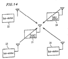
- the conventional radio communication apparatuses has another drawback, which is described with reference to Figure 14.
- a parent station 21 radio-communicates with four sub-stations 22 to 25 and only the parent station 21 can switch its antennas, as shown in Figure 14.
- the parent station 21 switches the antennas in response to data transmission from the sub-station 22, for example, good receiving conditions can be maintained in subsequent communication between the parent station 21 and the sub-station 22 without the need for the parent station 21 to switch its antennas.
- the space diversity effectively works.
- the parent station 21 receives data from any of the other sub-stations 23 to 25, it will have to switch the antennas with high probability to obtain good receiving conditions for new data.
- the sub-stations 22 to 25 transmit data to the parent station 21 one after another frequently, it becomes difficult for the parent station 21 to switch the antennas in obedience to such frequent data transmission from the different sub-stations. In such a case, the effect of the space diversity cannot be obtained sufficiently. This trouble will be overcome if the sub-stations 22 to 25 are also allowed to switch their antennas. Then, the necessity for the parent station 21 to switch its antennas for each of the sub-stations 22 to 25 will be reduced.
- EP-A-0 622 911 (IBM) relates to a mobile cellular communication system with a base station and a plurality of mobile stations.
- the system includes independent operation of antenna selection at both the base station and a mobile station, for selection of the best propagation path between the two stations.
- the invention provides a pair of radio communication apparatuses as set out in claim 1. Preferred features are set out in the dependent claims.
- the receiving antennas of the radio communication apparatus on the receiver side are switched by the receiving antenna switch circuit, but also the transmitting antennas of the radio communication apparatus on the transmitter side are also switched by the transmitting antenna switch circuit. Accordingly, a variety of combinations of the transmitting and receiving antennas can be realized, compared with the conventional space diversity method where the antennas are switched on only one of the transmitter and receiver sides. This increases the possibility of better transmission/receiving in a complicate radio wave circumstance.
- Each radio communication apparatus of the present invention is provided with both the transmitting antenna switch circuit and the receiving antenna switch circuit to effect both transmission and receiving.
- the radio communication apparatus on the transmitter side may be provided with only the transmitting antenna switch circuit, while the radio communication apparatus on the receiver side may be provided with only the receiving antenna switch circuit.
- the transmitting antennas can also be used as the receiving antennas.
- the same antenna switch circuit may be used as the transmitting antenna switch circuit at the transmission of data and as the receiving antenna switch circuit at the receiving of data.
- the transmitting antenna switch means on the transmitter side and the receiving antenna switch means on the receiver side execute the antenna switch processing in accordance with a predetermined antenna switch procedure. Accordingly, all the combinations of the transmitting and receiving antennas can be selected without fail.
- the antenna switch processing may not actually be executed on one of the transmitter and receiver sides in accordance with the antenna switch procedure.
- the antenna switch procedure may include steps where no antenna switching is not conducted on the transmitter side nor the receiver side at predetermined intervals.
- the antenna switch procedure can be designed so that the transmitting and receiving antennas can actually be switched only when the calculation result of the remainder of the switch count divided by the switch interval value is identical to a predetermined value. With such an antenna switch procedure, all the combinations of the transmitting and receiving antennas can be selected without fail only by the calculation between the current value of the switch count and a predetermined value.
- All transmitting data can be re-transmitted for a predetermined number of times, and the combination of the transmitting and receiving antennas can be changed every time the data is re-transmitted or every time the data is re-transmitted a plurality of times.
- the transmitting data can be received on the receiving side without fail.
- All the combinations of the transmitting and receiving antennas can also be realized by changing the combination sequentially every time a receiving error is detected on the receiver side or every time a plurality of receiving errors are detected on the receiver aide.
- combination free from the occurrence of a receiving error can be selected without fail.
- re-transmission of the data is no more conducted. This improves the time utilizing efficiency of data transmission.
- All the combinations of the transmitting and receiving antennas can also be realized by changing the combination sequentially every time low level receiving is detected on the receiver side or every time low level receiving is detected on the receiver side a plurality of times.
- a combination capable of realizing high level receiving can be selected without fail.
- the invention described herein makes possible the advantage of providing a radio communication apparatus which employs a space diversity method where antennas are switched both on the receiver and transmitter sides to ensure good data transmission/receiving even in a complicated radio wave environment.
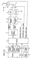
- Figure 1 is a block diagram showing the configuration of a terminal unit of Example 1 according to the present invention.
- Figure 2 is a block diagram showing the configuration of a terminal unit of Example 2 according to the present invention.
- Figure 3 is a block diagram showing the configuration of a terminal unit of Example 3 according to the present invention.
- Figure 4 is a flowchart of a transmission program used on the transmitter side in Example 3.
- Figure 5 is a block diagram showing the configuration of a terminal unit of Example 4 according to the present invention.
- Figure 6 is a flowchart of a transmission program used on the transmitter side in Example 4.
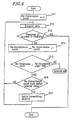
- Figure 7 is a flowchart of a receiving program used on the receiver side in Example 4.
- Figure 8 is a flowchart of a receiving program used on the receiver side in Example 5.
- Figure 9 is a flowchart of a transmission program used on the transmitter side in Example 5.
- Figure 10 is a block diagram showing the configuration of a terminal unit on the receiver side of Example 6 according to the present invention.
- Figure 11 is a flowchart of a receiving program used on the receiver side in Example 6.
- Figure 12 is a block diagram showing the configuration of a terminal unit on the receiver side of Example 7 according to the present invention.
- Figure 13 is a flowchart of a receiving program used on the receiver side in Example 7.
- Figure 14 shows a conventional radio communication system where communication is conducted between one parent station and a plurality of sub-stations.
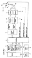
- Figure 1 is a block diagram showing the configuration of a terminal unit of Example 1.
- a terminal unit such as a work station and a shared printer provided with the radio transmission/receiving function used in a radio LAN and the like will be described.
- the terminal unit includes a controller 1 and a temporary memory 2 and a memory 3 which are connected with the controller 1 via buses.
- a CPU control processing unit
- a microcomputer or the like is used as the controller 1.
- the temporary memory 2 is a volatile memory such as a RAM (random access memory), while the memory 3 is a nonvolatile memory such as a ROM (read only memory) and a magnetic disk device.
- An input device 4 and an output device 5 are also connected with the controller 1 via buses.
- the input device 4 includes a keyboard or the like for operation input, an input interface with another device, and the like.
- the output device 5 includes a display, a printer, an output interface with another device, and the like.
- the controller 1 is connected with a parallel/serial converter 6 to allow parallel data to be input into/output from the controller 1.
- the parallel/serial converter 6 converts transmitting data sent in parallel from the controller 1 into serial data and outputs the serial data, while it converts received data input in serial into parallel data and sends the parallel data to the controller 1.
- the transmitting data output from the parallel/serial converter 6 is sent to a transmit/receive switch circuit 9 via a modulation section 7a of a modulator/demodulator 7 and a driver 8.
- the modulation section 7a of the modulator/demodulator 7 ia a circuit which modulates a transmitting carrier in accordance with transmitting data and outputs the resultant data as a transmitting signal.
- the driver 8 is a circuit which adjusts or converts the level of the transmitting signal.
- the transmitting signal sent to the transmit/receive switch circuit 9 is then output outside from a first antenna 11 or a second antenna 12 via an antenna switch circuit 10.
- a signal received through the first antenna 11 or the second antenna 12 is sent to a demodulation section 7b of the modulator/demodulator 7 via the antenna switch circuit 10, the transmit/receive switch circuit 9, and a receiver 13.
- the receiver 13 is a circuit which adjusts or converts the level of the received signal.
- the demodulation section 7b of the modulator/demodulator 7 demodulates the received signal. to obtain demodulated received data.
- the received data is sent in serial from the demodulation section 7b to the parallel/serial converter 6.
- the transmit/receive switch circuit 9 switches the output of the driver 8 and the input of the receiver 13 to connect one of them to the antenna switch circuit 10. This switching is controlled by a transmit/receive switch signal sent from the controller 1.
- the antenna switch circuit 10 switches the first and second antennas 11 and 12 to connect one of them to the transmit/receive switch circuit 9. This switching is controlled by an antenna switch signal sent from the controller 1.
- the first and second antennas 11 and 12 are transmitting/receiving antennas usable both for transmission and receiving, which are disposed at positions different from each other to effect the space diversity.
- the antenna switch circuit 10 selects one of the antennas to be used as the transmitting antenna.
- the antenna switch circuit 10 selects one of the antennas to be used as the receiving antenna.
- the controller 1 directly executes a program stored in the memory 3 or executes a program loaded to the temporary memory 2. Transmitting data and received data are processed in accordance with direct instructions written in the program or instructions input via the input device 4 during the execution of the program. Transmitting data and received data are actually processed by the controller 1 which executes transmission/receiving programs stored in the memory 3 or transmission/receiving programs loaded to the temporary memory 2. In the execution of the transmission/receiving programs, a portion of the temporary memory 2 is used as a buffer or other work areas as required.
- the controller 1 conducts the transmission operation in accordance with the transmission program.
- the controller 1 sends the transmit/receive switch signal to the transmit/receive switch circuit 9 to connect the output of the driver 8 to the antenna switch circuit 10.
- the controller 1 also sends the antenna switch signal to the antenna switch circuit 10, if required, to switch the first and second antennas 11 and 12.
- the controller 1 can also switch the first and second antennas 11 and 12 at a later stage during the transmission operation by sending the antenna switch signal appropriately. Transmitting data has been stored in the temporary memory 2 or the memory 3 or is input via the input device 4.
- the controller 1 sends the transmitting data to the parallel/serial converter 6 without processing or after processing such as data compression.
- transmitting data is divided into a plurality of blocks every predetermined length of data, and each block is provided with a redundant code for error detection and error correction before being sent to the parallel/serial converter 6.
- the transmitting data is converted into serial data by the parallel/serial converter 6 and then modulated by the modulation section 7a of the modulator/demodulator 7 to obtain a transmitting signal.
- the transmitting signal then passes through the driver 8, the transmit/receive switch circuit 9, and the antenna switch circuit 10 to be output from the first or second antenna 11 or 12.
- the controller 1 sends the transmit/receive switch signal to the transmit/receive switch circuit 9 to connect the antenna switch circuit 10 to the input of the receiver 13.
- the controller 1 also sends the antenna switch signal to the antenna switch circuit 10, if required, to switch the first and second antennas 11 and 12.
- the controller 1 can also switch the first and second antennas 11 and 12 at a later stage during the receiving operation by sending the antenna switch signal appropriately.
- Data received via the first or second antenna 11 or 12 is sent to the demodulation section 7b of the modulator/demodulator 7 through the antenna switch circuit 10, the transmit/receive switch circuit 9, and the receiver 13.
- the received data is demodulated by the demodulation section 7b and then converted into parallel data by the parallel/serial converter 6 to be sent to the controller 1.
- the controller 1 conducts error detection and error correction of the received data based on the redundant code attached to each block of the data.
- the received data is stored in the temporary memory 2 or the memory 3 without processing or after processing such as data recovery, and directly handed over to the execution program or output to the output device 5.
- the first and second antennas 11 and 12 can be switched during the transmission/receiving operations when an antenna switch requiring factor occurs, for example, when the same data is re-transmitted on the transmitter side, when a data receiving error occurs on the receiver side, or when the data receiving level is low on the receiver side.
- an antenna switch requiring factor occurs on either the transmitter side or the receiver side, it is required to switch both the transmitting and receiving antennas of the terminal units on the transmitter and receiver sides by allowing the other side to know the occurrence of the factor by itself or by notice.
- the transmission and receiving programs in the terminal units on the transmitter and receiver sides may be programmed so that, whenever an antenna switch requiring factor occurs, the antennas on the both sides should be switched in accordance with an antenna switch procedure where four combinations of the transmitting and receiving antennas shown in Table 1 are realized sequentially.
- the transmitting and receiving antennas are in combination 1 in Table 1
- the first antenna 11 is switched to the second antenna 12 only in the terminal unit on the receiver side, while no antenna switching is conducted in the terminal unit on the transmitter side, so as to realize combination 2.
- the antenna switch requiring factor is, for example, an increase in the bit error rate.
- the second antenna 12 is switched to the first antenna 11 in the terminal unit on the receiver side, while the first antenna 11 is switched to the second antenna 12 in the terminal unit on the transmitter side, so as to realize combination 3.
- Combination 3 is switched to combination 4 when another antenna switch requiring factor occurs, and combination 4 is returned to combination 1 when yet another antenna switch requiring factor occurs.
- the antenna switch processing is thus repeated in accordance with this antenna switch procedure.
- the number of times of the switching in the antenna switch processing where the first antenna 11 and the second antennas 12 are switched on at least one of the transmitter and receiver sides is four, which is equal to the total of the two transmitting antennas and the two receiving antennas. Accordingly, all the four combinations shown in Table 1 can be realized.
- the switching described in the above method is performed at a timing of, for example, a border between adjacent packets of information in time axis.
- the antenna switch processing according to the above antenna switch procedure is conducted in the following manner.
- a combination table as shown in Table 1, for example, is stored in a portion of the temporary memory 2, while a pointer indicating the current combination in the combination table is stored in another portion of the temporary memory 2.
- the pointer is shifted by one, and the current combination and the previous combination are compared, to determine whether or not the first antenna 11 and the second antenna 12 should be switched on the transmitter and receiver sides and switch if required.
- both the terminal units on the transmitter and receiver sides must be informed of the occurrence of the factor.
- the transmitting and receiving antennae may be switched independently on the transmitter and receiver sides without being synchronized. In this case, since the switchings on the transmitter and receiver sides are not synchronous, all the combinations of the first and second antennas 11 and 12 can be realized by shifting the switch timings from each other. Alternatively, the switch periods on the transmitter and receiver sides may be made different from each other or the antennas only on one side may be switched.
- the transmitting antennas of the terminal unit on the transmitter side may be switched sequentially at predetermined intervals to allow re-transmission only under such a deteriorated radio wave circumstance that no response to first transmission is received from the terminal unit on the receiver side. Then, once the transmitting antenna which can receive a response from the receiver side is selected, only the receiving antennas of the terminal unit on the receiver side can be switched depending on the receiving level and the like.
- the terminal units with the above configuration to transmit/receive data therebetween, not only the first and second antennas 11 and 12 as the receiving antennas of the terminal unit on the receiver side, but also the first and second antennas 11 and 12 as the transmit antennas of the terminal unit on the transmitter side can be switched. Accordingly, a variety of combinations of the transmitting and receiving antennas can be realized, compared with a terminal unit employing the conventional space diversity method where only the transmitting or receiving antennas on the transmitter or receiver side are switched. This makes it possible to transmit/receive data in a complicate radio wave circumstance, as well as increasing the possibility of better data transmission/receiving in a same radio wave circumstance.
- the transmitting and receiving antennas are switched in accordance with a predetermined antenna switch procedure, it is assured that all the four combinations of the two transmitting antennas and the two receiving antennas disposed on the transmitter and receiver sides, respectively, can be utilized to achieve the space diversity. All the four combinations of the transmitting and receiving antennas can also be realized when the transmitting and receiving antennas are switched on the transmitter and receiver sides independently from each other, though some combination(s) may appear twice or more before all the combinations appear (not in accordance with the present invention).
- the detection of the bit error rate and the reception error can be performed.
- Figure 2 is a block diagram showing the configuration of a terminal unit of Example 2.
- Example 2 a specific configuration of the terminal unit for conducting the antenna switch processing in accordance with the antenna switch procedure described in Example 1 will be described. Components having the same functions as those in Example 1 shown in Figure 1 are denoted by the same reference numerals, and the description thereof is omitted.
- the temporary memory 2 of each of the terminal units on the transmitter and receiver sides includes a switch count area 2a for storing the number of times of switching and a switch interval area 2b for storing a switch interval value.
- the switch count stored in the switch count area 2a corresponds to the number of times of the antenna switch processing executed in the transmission or receiving program due to the occurrence of an antenna switch requiring factor.
- the switch counts on the transmitter and receiver sides are increased simultaneously.
- the switch interval values stored in the switch interval areas 2b on the transmitter and receiver sides are constants set differently, which are loaded from the memory 3 and the like.
- the switch interval value is set at "1" on one side, while on the other side it is set at a value equal to the number of antennas disposed on the different side. In this example, therefore, the value is set at "1" on the receiver side and "2" on the transmitter side.
- the transmission and receiving programs in the terminal units on both sides are programmed to increment the switch count in the switch count area 2a and read the switch count as well as the switch interval value in the switch interval area 2b. Only when the remainder of the switch count divided by the switch interval value is "0" (mod [modulo] operation), the antenna switch signal is sent to the antenna switch circuit 10 to switch the first and second antennas 11 and 12.
- the switch interval value on the transmitter side is set at "2", while that on the receiver side is set at "1".
- the transmission and receiving programs in the terminal units on the transmitter and receiver sides are programmed to conduct the antenna switch processing as shown in Table 2 below.
- the remainder of the switch count divided by the switch interval value is calculated, and the first and second antennas 11 and 12 are switched to each other only when the calculation result is "0".
- the terminal units on the transmitter and receiver sides calculate the remainder of the switch count divided by the switch interval individually and determine whether or not the first and second antennas 11 and 12 should be switched. Accordingly, it is ensured that all of the four combinations of the two transmitting antennas and the two receiving antennas can be realized. Moreover, since the antenna switch procedure is determined only by the switch count and the switch interval value stored in the switch count area 2a and the switch interval area 2b, respectively, it is not necessary to store a combination table as shown in Table 1. Thus, the temporary memory 2 can be effectively used especially in the case where three or more antennas are disposed for each terminal unit.
- all of the four combinations of the transmitting and receiving antennas can be realized by executing the antenna switch processing four times even in the case where the initial states of the transmitting and receiving antennas are different and the case where the switch count values on the transmitter and receiver sides are different.
- Figure 3 is a block diagram showing the configuration of a terminal unit of Example 3.
- Figure 4 is a flowchart of a transmission program used on the transmitter side in this example.
- Example 3 a specific example of an antenna switch requiring factor which may occur in the terminal unit of Example 2 will be described.
- Components having the same functions as those in Examples 1 and 2 shown in Figures 1 and 2 are denoted by the same reference numerals, and the description thereof is omitted.
- the temporary memory 2 of each of the terminal units on the transmitter and receiver sides includes a re-transmission count area 2c for storing the number of times of re-transmission, a re-transmission upper limit area 2d for storing a re-transmission upper limit value, and the switch interval area 2b for storing the switch interval value.
- the re-transmission count stored in the re-transmission count area 2c corresponds to a value obtained by counting the number of times of re-transmission of same data.
- the re-transmission counts on the transmitter and receiver sides are always the same.
- the re-transmission count is substantially the same as the switch count.
- the re-transmission upper limit stored in the re-transmission upper limit area 2d is a constant shared by the transmitter and receiver sides, indicating the number of times of transmission allowed for same data.
- the re-transmission upper limit is set at "4" because the number of combinations of the transmitting and receiving antennas is 4.
- the setting of the switch interval value stored in the switch interval area 2b is as described in Example 2.
- the re-transmission count in the re-transmission count area 2c is initialized to "0" (step S1).
- Transmitting data is transmitted (step S2), incrementing the re-transmission count to "1" (step S3).
- the remainder of the re-transmission count divided by the switch interval value in the switch interval area 2b is calculated (step S4). If the remainder is "0", the antenna switch signal is sent to the antenna switch circuit 10 to switch the first and second antennas 11 and 12 on the transmitter side (step S5). If the remainder is not "0", the transmitting antenna is not switched.
- step S6 the re-transmission count and the re-transmission upper limit in the re-transmission upper limit area 2d are compared. If the re-transmission count has not reached the upper limit, the process returns to step S2 to re-transmit the same transmitting data. When the same transmitting data is transmitted four times by repeating the steps S2 through s6, the re-transmission count reaches "4" which is equal to the re-transmission upper limit in step S6. Then, the transmission operation is terminated.
- the terminal unit on the receiver side conducts a receiving operation similar to the above-described transmission operation.
- the re-transmission count is increased every time the data is received.
- the receiving antenna is switched between the first and second antennas 11 and 12 depending on the calculation result of the remainder of the re-transmission count divided by the switch interval value. Since the switch interval value on the receiver side is set at "1" in this example, the receiving antenna is switched every antenna switch processing. Accordingly, every time same transmitting data is re-transmitted, the combination of the transmitting and receiving antennas changes sequentially from the initial state through the state at the third antenna switch processing shown in Table 2. Thus, it is possible to transmit same data through all the four combinations of the transmitting and receiving antennas.
- same transmitting data is re-transmitted four times in accordance with the antenna switch procedure as described in Example 2. It is therefore possible to transmit/receive same data through all the combinations of the four transmitting and receiving antennas. This makes it possible for the terminal unit on the receiver side to select data with the best receiving conditions among four same data repeatedly received or to synthesize data from a plurality of received data appropriately. Thus, effective received data which is significantly less influenced by fading can be obtained even under a complicate radio wave circumstance.
- the operation shown in Figure 4 can be conducted for every block.
- the antenna switch processing (steps S4 and S5) is executed after the fourth transmission of same data, to return the combination of the transmitting and receiving antennas to the initial state.
- the processing in step S6 may follow immediately after the fourth transmission in step S2 to terminate the transmission operation. In this case, though the initial state of the transmitting and receiving antennas changes at the next transmission operation, no trouble will arise.
- the antenna switch processing was executed every re-transmission. Alternatively, it may be executed every time re-transmission is repeated a plurality of times.
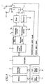
- Figure 5 is a block diagram showing the configuration of a terminal unit on the receiver side of Example 4.
- Figure 6 is a flowchart of a transmission program on the transmitter side.
- Figure 7 is a flowchart of a receiving program on the receiver side.
- Example 4 another example of an antenna switch requiring factor which may occur in the terminal unit of Example 2 will be described.
- Components having the same functions as those in Examples 1 and 2 shown in Figures 1 and 2 are denoted by the same reference numerals, and the description thereof is omitted.
- the hardware configuration of the terminal unit on the transmitter side is the same as that shown in Example 3.
- the temporary memory 2 of the terminal unit on the receiver side includes a receiving error count area 2e for storing the number of receiving errors and the switch interval area 2b for storing the switch interval value.
- the receiving error count stored in the receiving error count area 2e corresponds to the number of times counted every time an uncorrectable error is detected in received data and determined as a receiving error.
- the setting of the switch interval value stored in the switch interval area 2b is as described in Example 2.
- an error detection coda and an error correction code are attached to transmitting data before the data is transmitted.
- a receiving program on the receiver side is programmed to detect an error in the received data and correct it, as required, based on these redundant codes.
- the terminal unit on the receiver side recognizes it as an receiving error and sends a response indicating the error to the transmitter side, requesting re-transmission of the same data.
- the terminal unit on the transmitter side re-transmits the data only upon receipt of the response indicating an error from the receiver side.
- the case where data has not reached the receiver side due to failure in receiving the data can also be treated as the receiving error. If no redundant code is attached to transmitting data, the receiving error arises only in the case of failure in receiving data.
- the receiving error count is therefore counted simultaneously with the re-transmission count in the re-transmission count area 2c shown in Figure 3 on the transmitter side, and the receiving error count and the re-transmission count are substantially the same as the switch count in Example 2.
- the response from the receiver side itself may include an error.
- the transmission program on the transmitter side is programmed to re-transmit same data when no response indicating success in receiving data is received from the receiver side.
- the receiving error count on the receiver side and the re-transmission count on the transmitter side may become different from each other.
- the re-transmission upper limit in the re-transmission upper limit area 2d shown in Figure 3 is used to terminate the transmission operation abnormally. Accordingly, though the upper limit value may be set at "4" corresponding to the number of combinations of the transmitting and receiving antennas as in Example 3, it may also be set at a value larger than "4".
- the procedure of the transmission program in the terminal unit on the transmitter side will be described.
- the re-transmission count in the re-transmission count area 2c is initialized to "O" (step S11).
- Transmitting data is transmitted (step S12) and then a response from the receiver side is waited for (step S13). If a response indicating success in receiving the data is received from the receiver side, the transmission of the current transmitting data is terminated.
- the re-transmission count is increased by "1" (step S14), and then the re-transmission count and the re-transmission upper limit are compared (step S15). If the re-transmission count has not reached the upper limit, the remainder of the re-transmission count divided by the switch interval value is calculated as the antenna switching processing (step S16). If the remainder is "0", the transmitting antenna is switched (step S17). If the remainder is not "0", the transmitting antenna is not switched. In this example, since the switch interval value on the transmitter side is set at "2", the transmitting antenna is switched every other antenna switch processing.
- step S12 the process returns to step S12 to re-transmit the same data, and the processings in steps S12 to S17 are repeated until a response indicating success in receiving the data is received from the receiver side. If the re-transmission count reaches the re-transmission upper limit, the transmission operation is terminated abnormally, concluding that any combination of the transmitting and receiving antennas will cause a receiving error or that too many receiving errors are found.
- the operation shown in Figure 6 can be conducted for every block.
- step S21 After the receiving error count in the receiving error count area 2e is initialized to "0" (step S21), the transmitted data is received (step S22), and the receiving result is examined (step S23). If the data is successfully received, a response indicating the success is sent to the transmittar side (step S24). The process returns to step S21 to initialize the receiving error count and waits for next data transmission (step S22). Even if data is consecutively transmitted from the same terminal unit, the control of the antenna switch processing with the receiving error count is no more required. Accordingly, the receiving error count is initialized at this point to be ready for transmission from other terminal units.
- step S23 If it is determined that a receiving error has occurred in step S23, a response indicating failure in receiving the data is sent to the transmitter side, requesting re-transmission of the same data (step S25). Simultaneously, the receiving error count is increased by "1" (step S26). Then, the remainder of the receiving error count divided by the switch interval value is calculated as the antenna switching processing (step 827). If the remainder is "0", the receiving antenna is switched in response to the antenna switch signal (step S28). If the remainder is not "0", the receiving antenna is not switched. In this example, since the switch interval value on the receiver side is set at "1", the receiving antenna is switched every antenna switch processing.
- step S22 the process returns to step S22 to wait for re-transmission of the same data, and the processings in steps S22 to S28 are repeated until the re-transmission is successful.
- the process waits for next data transmission in step S22.
- the combination of the transmitting and receiving antennas is sequentially changed with the antenna switch processing every time data is re-transmitted due to the occurrence of a receiving error.
- all the combinations of the transmitting and receiving antennas can be realized when the antenna switching processing has been repeated four times. Therefore, according to this example, if a combination of the transmitting and receiving antennas which can provide a radio wave condition where no receiving error occurs exists among the four combinations, this combination can be selected without fail to effect data transmission/receiving free from an error.
- re-transmission was repeated for a predetermined number of times regardless of the radio wave condition. This reduces the time utilizing efficiency of data transmission.
- re-transmission is terminated once a combination of the transmitting and receiving antennas free from the occurrence of a receiving error is selected. Moreover, when subsequent data is transmitted/received between the same terminal units, the same combination of the transmitting and receiving antennas free from the occurrence of a receiving error can be used. This increases the transmission rate.
- the antenna switch processing was executed every occurrence of a receiving error. Alternatively, it may be executed every time a plurality of receiving errors have occurred.
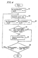
- Figure 8 is a flowchart of a receiving program on the receiver side
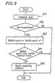
- Figure 9 is a flowchart of a transmission program on the transmitter side.
- Example 5 still another example of an antenna switch requiring factor which may occur in the terminal unit of Example 2 will be described.
- Components having the same functions as those in Examples 1 and 2 shown in Figures 1 and 2 are denoted by the same reference numerals, and the description thereof is omitted.
- Some communication protocols allow for automatic detection of a receiving error and re-transmission of data.
- a circuit unit executing one of such protocols When a circuit unit executing one of such protocols is used, the occurrence of individual receiving errors and the subsequent re-transmission of data cannot be detected in advance. Accordingly, it is impossible to execute the antenna switch processing every re-transmission of data due to the occurrence of a receiving error as described in Example 4. In this example, therefore, if currently received data is re-transmitted data, it is detected after the data has been received, and the antenna switch processing is conducted when the re-transmitted data has been received.
- the hardware structure of the terminal units on the transmitter and receiver sides of this example is the same as that in Example 2 shown in Figure 2.
- the parallel/serial converter 6 in this example conducts processings other than the parallel-serial conversion of transmitting data and the serial-parallel conversion of receive data. That is, the parallel/serial converter 6 on the receiver side detects a receiving error in received data any time and sends a response to the transmitter side automatically, while the parallel/serial converter 6 on the transmitter side re-transmits transmitted data automatically on receipt of the response indicating a receiving error from the receiver side. Accordingly, the controller 1 on the receiver side just receives received data from the parallel/serial converter 6, not required to conduct detection of a receiving error and other processings.
- the controller 1 on the transmitter side just transmits transmitting data to the parallel/serial converter 6, not required to conduct re-transmission and other processings.
- the receiving program executed by the controller 1 on the receiver side is programmed so as to detect whether the received data has been received in the first transmission or after repeated re-transmission based on the timing at which data is sequentially received from the parallel/serial converter 6, the control signal attached to the received data, or a control signal (not shown) output from the parallel/serial converter 6.
- the transmission program executed by the controller 1 on the transmitter side is programmed so as to detect whether the transmitting data has been successfully received in the first transmission or after repeated re-transmission based on the timing at which the transmitting data is sequentially received by the parallel/serial converter 6 or a control signal (not shown) output from the parallel/serial converter 6.
- step S31 After the switch count in the switch count area 2a is initialized to "0" (step S31), data is received (step S32), and whether or not the received data has been successfully received in the first transmission is examined (step S33). If the received data is determined to have been received in the first transmission, the process returns to step S31 to initialize the switch count and wait for next data transmission. Even if data is consecutively transmitted from the same terminal unit, the control of the antenna switch processing with the switch count is no more required. Accordingly, the switch count is initialized at this point to be ready for transmission from other terminal units.
- the above examination and the determination for the received data can be performed by, for example, the parity check, the sum check, the CRC check, the sequence number check, and the like.
- step S34 the switch count is increased by "1" (step S34). Then, the remainder of the switch count divided by the switch interval value is calculated as the antenna switching processing (step S35). If the remainder is "0", the receiving antenna is switched (step S36). If the remainder is not "0", the receiving antenna is not switched. In this example, since the switch interval value on the receiver side is set at "1", the receiving antenna is switched every antenna switch processing. Then, the process returns to step S32 to wait for re-transmission of the same data.
- the switch count in the switch count area 2a is initialized to "0" only when the power source is on or when the terminal unit on the receiver side is changed to another terminal unit.
- Transmitting data is transmitted (step S41), and then whether or not the transmitting data has been re-transmitted is examined (step S42). This examination is performed by the controller 1, the temporary memory 2 and the memory 3 by checking a history of the operation. If the transmitting data is determined to have been successfully received in the first transmission, the transmission is terminated. If the transmitting data is determined to have failed in being received at least one time and have been re-transmitted, the switch count is increased by "1" (step S43).
- the successful reception can be detected by receiving a response from the reception side.
- the response is governed by a communication protocol used.
- a packet indicating the successful reception is sent from the reception side to the transmission side.
- the successful reception can be determined by receiving this packet.
- the remainder of the switch count divided by the switch interval value is calculated as the antenna switching processing (step S44). If the remainder is "0", the transmitting antenna is switched (step S45). If the remainder is not "0", the transmitting antenna is not switched. In this example, since the switch interval value on the transmitter side is set at "2", the transmitting antenna is switched every other antenna switch processing of the steps S42, S43 and S44. After the antenna switch processing is complete, the transmit operation is terminated.
- the combination of the transmitting and receiving antennas cannot be sequentially changed unless transmission/receiving is continuously conducted between the same terminal units. For this reason, as shown in Figure 8, when the antenna switch processing is executed (steps S35 and S36), the receiving program on the receiver side is programmed to wait for next data transmission in step S32 without initializing the switch count. Similarly, when data is transmitted to the same terminal unit, the transmission program on the transmitter side is programmed to transmit data without initializing the switch count.
- this combination can be selected without fail to effect data transmission/receiving free from an error.
- effective antenna switch processing can be executed without the necessity of detection of a receiving error and re-transmission of data in the transmission and receiving programs.
- the antenna switch processing was executed every occurrence of a receiving error. Alternatively, it may be executed every time a plurality of receiving errors have occurred.
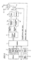
- Figure 10 is a block diagram showing the configuration of a terminal unit of Example 6.
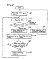
- Figure 11 is a flowchart of a receiving program on the receiver side.
- Example 6 still another example of an antenna switch requiring factor which may occur in the terminal unit of Example 2 will be described.
- Components having the same functions as those in Examples 1 and 2 shown in Figures 1 and 2 are denoted by the same reference numerals, and the description thereof is omitted.
- a temporary memory 2 of the terminal unit on the receiver side includes a low level receiving count area 2f for storing a low level receiving count and the switch interval area 2b for storing the switch interval value.
- the low level receiving count stored in the low level receiving count area 2f corresponds to the number of times of the detection of low level received data. This detection is accomplished by detecting the signal level and the like of received data in the demodulation section 7b of the modulator/demodulator 7. The detection result is sent to the controller 1 as a receiving level signal.
- the detection of low level receiving is announced to the transmitter side, which therefore becomes a common antenna switch requiring factor on both the transmitter and receiver sides. Accordingly, the low level receiving count on the receiver side is increased simultaneously with the increment of the switch count on the transmitter side, and the values of the two counts are substantially the same.
- the setting of the switch interval value stored in the switch interval area 2b is as described in Example 2.
- step S51 After the low level receiving count in the low level receiving count area 2f is initialized to "0" (step S51), data is received (step S52), and the receiving level is examined (step S53). If the receiving level is not low, the process returns to step S51 to initialize the low level receiving count and waits for next data transmission (step S52). Even if data is consecutively transmitted from the same terminal unit, the control of the antenna switch processing with the low level receiving count is no more required. Accordingly, the low level receiving count is initialized at this point to be ready for transmission from other terminal units.
- step S53 If the receiving level is determined to be low in step S53, a response indicating the low level receiving is sent to the transmitter side (step S55). Simultaneously, the low level receiving count is increased by "1" (step S55). Then, the remainder of the low level receiving count divided by the switch interval value is calculated as the antenna switching processing (step S56). If the remainder is "0", the receiving antenna is switched (step S57). If the remainder is not "0", the receiving antenna is not switched. In this example, since the switch interval value on the receiver side is set at "1", the receiving antenna is switched every antenna switch processing. Then, the process returns to step S52 to wait for next data transmission.
- the procedure of the transmission program in the terminal unit on the transmitter side is substantially the same as that in Example 5 shown in Figure 9. The difference is that the examination of whether or not the transmitting data has been re-transmitted in step S42 is replaced with the examination of whether or not a response indicating low level receiving has been received from the receiver side.
- the switch count is increased (step S43) and the antenna switch processing is conducted (steps S44 and S45).
- the combination of the transmitting and receiving antennas is sequentially changed with the antenna switch processing every time low level receiving is detected.
- all the combinations of the transmitting and receiving antennas can be realized when the antenna switching processing has been repeated four times.
- re-transmission is not conducted even when the receiving level is low. Accordingly, the antenna switch processing is executed only once for each transmission/receiving operation.
- the combination of the transmitting and receiving antennas cannot be sequentially changed unless transmission/receiving is continuously conducted between the same terminal units.
- the receiving program on the receiver side is programmed to wait for next data transmission in step S52 without initializing the low level receiving count.
- the transmission program on the transmitter side is programmed to transmit data without initializing the switch count.
- this combination can be selected without fail to effect better data transmission/receiving.
- the antenna switch processing was executed every time low level receiving is detected. Alternatively, it may be executed every time low level receiving is detected a plurality of times.
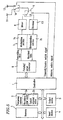
- Figure 12 is a block diagram showing the configuration of a terminal unit of Example 7.
- Figure 13 is a flowchart of a receiving program on the receiver side.
- Example 7 still another example of an antenna switch requiring factor which may occur in the terminal unit of Example 2 will be described.
- Components having the same functions as those in Examples 1 and 2 shown in Figures 1 and 2 are denoted by the same reference numerals, and the description thereof is omitted.
- the combination of the transmitting and receiving antennas is changed when the receiving level on the receiver side is low.
- the terminal unit on the receiver side receives data transmitted from a plurality of terminal units on the transmitter side.
- the hardware configuration of the terminal units on the transmitter side is the same as that in Example 2 shown in Figure 2.
- the temporary memory 2 of the terminal unit on the receiver side includes the low level receiving count area 2f for storing the low level receiving count, the switch interval area 2b for storing the switch interval value, and a source address area 2g for storing a source address.
- the setting of the low level receiving count stored in the low level receiving count area 2f is the same as that described in Example 6.
- the result of the detection of the receiving level obtained in the demodulation section 7b of the modulator/demodulator 7 is sent to the controller 1 as a receiving level signal.
- the setting of the switch interval value stored in the switch interval area 2b is as described in Example 2.
- the source address stored in the source address area 2g corresponds to the address detected at the start of data receiving.
- the source address is an identification code for identifying the terminal unit on the transmitter side. The source address may not be detected when a receiving error occurs in received data. It can be detected, however, as far as data is received though the level thereof may be low.
- the procedure of the transmission program in the terminal unit on the transmitter side is the same as that described in Example 6. Referring to Figure 13, the procedure of the receiving program in the terminal unit on the receiver side will be described.
- a dummy address is stored in the source address area 2g (step S61), and the low level receiving count in the low level receiving count area 2f is initialized to "0" (step S62).
- data is received (step S63).
- the data receiving in this example refers to the receiving of all of a series of data including all blocks, if the data is divided into a plurality of blocks, because these blocks have the common source address.
- the level of the received data is examined (step S64).
- step S65 If it is determined that the receiving level is not low, the source address is changed to the address of the transmitter of the current received data (step S65). Then, the process returns to step S62 to initialize the low level receiving count and waits for next data transmission (step S63). The low level receiving count is initialized for the same reason as described in Example 6.
- step S66 If the receiving level is determined to be low in step S64, whether or not the source address is a dummy is examined (step S66). If the low level data is the first received data, the source address is a dummy. Thus, the source address is changed to the address of the transmitter of the current received data as in step S65 (step S67). Then, a response indicating the receipt of low level data is sent to the transmitter (step S68), and simultaneously the low level receiving count is increased by "1" (step S69). Then, the remainder of the low level receiving count divided by the switch interval value is calculated as the antenna switching processing (step S70). If the remainder is "0", the receiving antenna is switched (step S71). If the remainder is not "0", the receiving antenna is not switched. In this example, since the switch interval value on the receiver side is set at "1", the receiving antenna is switched every antenna switch processing. After the completion of the antenna switch processing, the process returns to step S63 to wait for next data transmission.
- step S72 whether or not the stored source address and the source address of the currently received data are identical to each other is examined, (step S72). If they are identical, i.e., if data received from the same transmitter is determined low again, the response to the transmitter (step S68), the increment of the low level receiving count (step S69), end the antenna switch processing (steps S70 and S71) are executed as described above. The process then returns to step S63 and waits for next data transmission.
- the combination of the transmitting and receiving antennas is sequentially changed with the antenna switch processing. Accordingly, a combination with which the receiving level is not low can be selected among the four combinations without fail, if such a combination exists.
- step S72 If data is received from a different transmitter and the level of the data is determined low, the source address of the currently received data is determined to be different from the stored source address in step S72. In this case, the stored source address is replaced with the source address of the currently received data without executing the antenna switch processing (step S65). Then, the process returns to step S62 to initialize the low level receiving count and waits for next data transmission (step S63).
- the antenna switch processing is not executed when received data from the new transmitter is determined low first. Instead, the combination of the transmitting and receiving antennas used last time for the previous transmitter is retained. This procedure is advantageous in such a case that data from the new transmitter lasts only once and subsequently data from the previous transmitter follows.
- Data from the previous transmitter can be received without repeating the antenna switch processing.
- the stored source address and the source address of currently received data are determined identical to each other in step S72. Then, the antenna switch processing is executed to select a combination suitable for the new transmitter.
- the combination of the transmitting and receiving antennas is sequentially changed with the antenna switch processing every time low level receiving data is detected as in Example 6. Accordingly, if a combination of the transmitting and receiving antennas which can provide a radio wave condition where the receiving level is not low exists among the four combinations, this combination can be selected without fail to effect better data transmission/receiving.
- the antenna switch processing is not executed for the first data receiving from the new transmitter even when a low level is detected in the data.
- the combination of the transmitting and receiving antennas will not be changed unnecessarily.
- the antenna switch processing was executed every time low level receiving from the same transmitter is detected. Alternatively, it may be executed every time low level receiving from the same transmitter is detected a plurality of times.
- the two antennas 11 and 12 were switched therebetween. It is also possible to configure to conduct the switching among three or more antennas without substantially changing the configuration described above.
- the switch interval values on the transmitter and receiver sides were set at "2" and "1", respectively. However, they can be set at any appropriate values depending on the number of antennas and other conditions. For example, the switch interval values on the transmitter and receiver sides may be set at "4" and "2", respectively. In such a case, the combination of the transmitting and receiving antennas is changed every other antenna switch processing. Thus, all of the four combinations will be realized after the antenna switch processing has been executed eight times, In Examples 2 to 7, the transmitting and receiving antennas were switched when the remainder of a certain count value divided by the switch interval value is "0". Any value of the remainder can also be used as far as it is less than the switch interval value.
- the switch count area 2a, the switch interval area 2b, the re-transmission count area 2c, the re-transmission upper limit area 2d, the receiving error count area 2e, the low level receiving count area 2f, and the source address area 2g in the above examples may be entirely or partially located in the memory 3, instead of the temporary memory 2.
- the terminal units provided with transmission/receiving circuits were used in the above examples. Instead, a terminal unit provided with either a transmission circuit or a receiving circuit can also be used in combination with another terminal unit.
- the present invention is also applicable to radio communication apparatuses other than the exemplified terminal units.
- the radio communication apparatus of the present invention a variety of data receiving conditions can be realized by switching antennas on both the transmitter and receiver sides. As a result, the effect of the space diversity can be obtained sufficiently even under a complicate radio wave circumstance or an deteriorated radio wave circumstance.
- the radio communication apparatuses on the transmitter and receiver sides repeat the antenna switch processing independently, all the combinations of the transmitting and receiving antennae can be selected without fail though some combination(s) may appear twice or more before all the combinations appear (not in accordance with the invention). If the radio communication apparatuses on the transmitter and receiver sides execute the antenna switch processing in accordance with a predetermined antenna switch procedure programmed to select all the combinations of the transmitting and receiving antennas, all the combinations can be selected without allowing any combination(s) to appear twice.
- the antenna switch procedure can be determined only by the calculation between the current value of the switch count and a predetermined value.
- Transmitting data can be repeatedly re-transmitted through all the combinations of the transmitting and receiving antennas to ensure the transmission of the data to the receiver side.
- a combination of the transmitting and receiving antennas through which data can be received under better conditions can be selected among all the combinations without fail.
- a combination of the transmitting and receiving antennas through which data can be transmitted without an error can be selected without fail.
Landscapes
- Engineering & Computer Science (AREA)
- Computer Networks & Wireless Communication (AREA)
- Signal Processing (AREA)
- Radio Transmission System (AREA)
- Mobile Radio Communication Systems (AREA)
Claims (7)
- Paar von Funkkommunikationsvorrichtungen auf einer Senderseite und einer Empfängerseite zum Durchführen eines Datensendens und -empfangens über eine Funkkommunikation durch ein Raum-Diversity-Verfahren, bei dem eine Vielzahl von Antennen (11, 12) dazwischengeschaltet wird, wobei
die Funkkommunikationsvorrichtung auf der Senderseite eine Sendeschaltung (1-6, 7a) zum Durchführen einer Datensendung und eine Sendeantennen-Umschaltschaltung (10) zum Auswählen einer Sendeantenne unter einer Vielzahl von Sendeantennen (11, 12) zum Senden von Funkwellen und zum Verbinden der ausgewählten Sendeantenne mit der Sendeschaltung (1-6, 7a) umfasst, und
die Funkkommunikationsvorrichtung auf der Empfängerseite eine Empfangsschaltung (1-6, 7a) zum Durchführen eines Datenempfangens und eine Empfangsantennen-Umschaltschaltung (10) zum Auswählen einer Empfangsantenne unter einer Vielzahl von Empfangsantennen (11, 12) auf der Empfängerseite zum Empfangen der Funkwellen und zum Verbinden der ausgewählten Empfangsantenne mit der Empfangsschaltung umfasst,
die Funkkommunikationsvorrichtung auf der Senderseite weiter eine Sendeantennen-Umschalteinrichtung (1) zum Ausführen einer Antennenumschaltverarbeitung durch ein Steuern, ob die Sendeantennen von der Sendeantennen-Umschaltschaltung (10) umgeschaltet werden oder nicht, umfasst, und
die Funkkommunikationsvorrichtung auf der Empfängerseite weiter eine Empfangsantennen-Umschalteinrichtung (1) zum Ausführen einer Antennenumschaltverarbeitung durch ein Steuern, ob die Empfangsantennen (11, 12) von der Empfangsantenne-Umschaltschaltung (10) umgeschaltet werden oder nicht, umfasst, und wobei eine Empfangsantenne in Übereinstimmung mit der Antennenumschaltverarbeitung gewählt wird,
dadurch gekennzeichnet, dass,
wenn ein Antennenumschalt-Anforderungsfaktor auf entweder der Senderseite oder der Empfängerseite auftritt, sowohl die Sendeantennen-Umschaltschaltung als auch die Empfangsantennen-Umschaltschaltung das Auftreten des Faktors erkennen und eine jeweilige Antennenumschaltverarbeitung ausführen;
jede der Funkkommunikationsvorrichtungen auf der Senderseite und der Empfängerseite weiter eine Umschaltzähleinrichtung (2a) zum Zählen der Anzahl von Malen eines Umschaltens, das sowohl von der Sendeantennen-Umschaltschaltung (10) als auch von der Empfangsantennen-Umschaltschaltung (10) ausgeführt wird, umfasst; und
die Umschaltverarbeitung derart ist, dass, wenn sowohl die Sendeantennen-Umschaltschaltung (10) als auch die Empfangsantennen-Umschaltschaltung (10) die Sendeantennen (11, 12) und die Empfangsantennen (11, 12) gleichzeitig umschalten oder eine der Sendeantennen-Umschaltschaltung und der Empfangsantennen-Umschaltschaltung die Sende- oder Empfangsantennen umschaltet und ein Umschaltzählwert, der von der Umschalt-Zähleinrichtung (2a) gezählt ist, gleich einem Produkt der Anzahl der Sendeantennen und der Anzahl der Empfangsantennen ist, sämtliche Kombinationen der Sendeantennen und der Empfangsantennen, die mittels der Sende- und Empfangsantennen-Umschaltschaltung verwirklicht sind, unterschiedlich voneinander sind. - Paar von Funkkommunikationsvorrichtungen nach Anspruch 1, wobei
die Sendeantennen-Umschalteinrichtung (1) ausgelegt ist, es zuzulassen, dass die Sendantennen-Umschaltschaltung (10) die Sendeantennen (11, 12) in einer vorbestimmten Reihenfolge nur umschaltet, wenn ein Rest des Umschaltzählwerts, der von der Umschalt-Zähleinrichtung (2a) auf der Senderseite gezählt ist, geteilt durch einen vorbestimmten Sendeumschalt-Intervallwert, null ist, und
die Empfangsantennen-Umschalteinrichtung (1) ausgelegt ist, es zuzulassen, dass die Empfangsantennen-Umschaltschaltung die Empfangsantennen in einer vorbestimmten Reihenfolge nur umschaltet, wenn ein Rest des Umschaltzählwerts, der von der Umschalt-Zähleinrichtung (2a) auf der Empfängerseite gezählt ist, geteilt durch einen vorbestimmten Empfangsumschalt-Intervallwert null ist. - Paar von Funkkommunikationsvorrichtungen nach Anspruch 1 oder Anspruch 2, wobei die Funkkommunikationsvorrichtung auf der Senderseite weiter eine Rücksendeeinrichtung zum Senden von Daten wiederholt für eine vorbestimmte Anzahl von Malen umfasst, und die Sendeantenne-Umschalteinrichtung (1) die Antennenumschaltverarbeitung jedes Mal ausführt, wenn die Daten gesendet werden, und
die Funkkommunikationsvorrichtung auf der Empfängerseite weiter eine Empfangsdaten-Synthetisierungseinrichtung zum Auswählen oder Synthetisieren effektiver empfangener Daten von einer Vielzahl empfangener Daten jedes Mal, wenn Daten eine Vielzahl von Malen empfangen werden, umfasst, und die Empfangsantennen-Umschalteinrichtung (1) die Anterinenumschaltverarbeitung jedes Mal ausführt, wenn die Daten empfangen werden. - Paar von Funkkommunikationsvorrichtungen nach Anspruch 1 oder Anspruch 2, wobei
die Funkkommunikationsvorrichtung auf der Senderseite weiter eine Rücksendeeinrichtung zum Rücksenden zuvor gesendeter Daten, wenn eine Antwort, die eine Erfassung eines Empfangsfehlers anzeigt, von der Funkkommunikationsvorrichtung auf der Empfängerseite empfangen wird, oder eine Antwort, die einen Erfolg bei einem Empfangen der Daten anzeigt, nicht empfangen wird, umfasst, und die Sendeantennen-Umschalteinrichtung (1) die Antennenumschaltverarbeitung ausführt, wenn die Rücksendeeinrichtung die gesendeten Daten zurücksendet, und
die Funkkommunikationsvorrichtung auf der Empfängerseite weiter eine Empfangsfehler-Erfassungseinrichtung zum Erfassen eines Empfangsfehlers empfangener Daten und eine Antworteinrichtung zum Senden einer Antwort zu der Funkkommunikationsvorrichtung auf der Senderseite über eine Funkkommunikation umfasst, wenn die Empfangsfehler-Erfassungseinrichtung einen Empfangsfehler erfasst, oder wenn die Daten erfolgreich empfangen worden sind, und die Empfangsantennen-Umschalteinrichtung (1) die Antennenumschaltverarbeitung jedes Mal ausführt, wenn die Empfangsfehler-Erfassungseinrichtung einen Empfangsfehler erfasst. - Paar von Funkkommunikationsvorrichtungen nach Anspruch 1 oder Anspruch 2, wobei
die Funkkommunikationsvorrichtung auf der Empfängerseite weiter eine Rücksende-Empfangserfassungseinrichtung zum Erfassen umfasst, dass die empfangenen Daten zurückgesendete Daten sind, und die Empfangsantennen-Umschalteinrichtung (1) die Antennenumschaltverarbeitung ausführt, wenn die Rücksende-Empfangserfassungseinrichtung erfasst, dass die empfangenen Daten zurückgesendete Daten sind, und
die Funkkommunikationsvorrichtung auf der Senderseite weiter eine Rücksende-Erfassungseinrichtung zum Erfassen, dass die gesendeten Daten durch die Rücksendung erfolgreich empfangen worden sind, und die Sendeantennen-Umschalteinrichtung die Antennenumschaltverarbeitung ausführt, wenn die Rücksende-Erfassungseinrichtung einen Erfolg bei einem Senden von Daten durch eine Rücksendung erfasst. - Paar von Funkkommunikationsvorrichtungen nach Anspruch 1 oder Anspruch 2, wobei
die Funkkommunikationsvorrichtung auf der Empfängerseite weiter eine Empfangspegel-Erfassungseinrichtung zum Erfassen eines Empfangspegels empfangener Daten und eine Antworteinrichtung zum Senden einer Antwort zu der Funkkommunikationsvorrichtung auf der Senderseite über eine Funkkommunikation umfasst, wenn die Empfangspegel-Erfassungseinrichtung einen niedrigen Empfangspegel erfasst, und die Empfangsantennen-Umschalteinrichtung (1) die Antennenumschaltverarbeitung ausführt, wenn die Empfangspegel-Erfassungseinrichtung einen niedrigen Empfangspegel erfasst, und
die Sendeantennen-Umschalteinrichtung der Funkkommunikationsvorrichtung auf der Senderseite die Antennenumschaltverarbeitung ausführt, wenn eine Antwort, die eine Erfassung eines niedrigen Empfangspegels anzeigt, von der Funkkommunikationsvorrichtung auf der Empfängerseite empfangen wird. - Paar von Funkkommunikationsvorrichtungen nach Anspruch 6, wobei die Funkkommunikationsvorrichtung auf der Empfängerseite weiter eine Quellenadress-Speichereinrichtung (2g) zum Speichern einer Adresse eines Senders von zuvor empfangenen Daten und eine Antennenumschalt-Zurückhaltungseinrichtung zum Instruieren der Empfangsantennen-Umschalteinrichtung, die Ausführung der Antennenumschaltverarbeitung zurückzuhalten, und zum Instruieren der Antworteinrichtung, das Senden der Antwort zu der Senderseite zurückzuhalten, wenn eine Adresse eines Senders von gegenwärtig empfangenen Daten unterschiedlich von der Quellenadresse ist, die in der Quellenadress-Speichereinrichtung (2g) gespeichert ist, umfasst.
Applications Claiming Priority (3)
| Application Number | Priority Date | Filing Date | Title |
|---|---|---|---|
| JP10443395A JP3250708B2 (ja) | 1995-04-27 | 1995-04-27 | 無線通信装置 |
| JP104433/95 | 1995-04-27 | ||
| JP10443395 | 1995-04-27 |
Publications (3)
| Publication Number | Publication Date |
|---|---|
| EP0740430A2 EP0740430A2 (de) | 1996-10-30 |
| EP0740430A3 EP0740430A3 (de) | 1997-01-15 |
| EP0740430B1 true EP0740430B1 (de) | 2003-11-12 |
Family
ID=14380545
Family Applications (1)
| Application Number | Title | Priority Date | Filing Date |
|---|---|---|---|
| EP96302974A Expired - Lifetime EP0740430B1 (de) | 1995-04-27 | 1996-04-26 | Diversity-Funkübertragungssystem |
Country Status (4)
| Country | Link |
|---|---|
| US (1) | US5799245A (de) |
| EP (1) | EP0740430B1 (de) |
| JP (1) | JP3250708B2 (de) |
| DE (1) | DE69630629T2 (de) |
Cited By (2)
| Publication number | Priority date | Publication date | Assignee | Title |
|---|---|---|---|---|
| US6961545B2 (en) | 2001-04-09 | 2005-11-01 | Atheros Communications, Inc. | Method and system for providing antenna diversity |
| US8086195B2 (en) | 2008-02-22 | 2011-12-27 | Motorola Mobility, Inc. | Communication unit and method of operation therefor |
Families Citing this family (44)
| Publication number | Priority date | Publication date | Assignee | Title |
|---|---|---|---|---|
| DE69637911D1 (de) * | 1995-07-19 | 2009-06-04 | Nec Corp | Diversity-Übertragungssystem mit Kodevielfachzugriff |
| JP3111906B2 (ja) * | 1996-07-17 | 2000-11-27 | 日本電気株式会社 | 無線基地局装置 |
| US6289209B1 (en) | 1996-12-18 | 2001-09-11 | Micron Technology, Inc. | Wireless communication system, radio frequency communications system, wireless communications method, radio frequency communications method |
| JPH118577A (ja) * | 1997-06-17 | 1999-01-12 | Saitama Nippon Denki Kk | 無線機 |
| KR100433901B1 (ko) * | 1998-02-21 | 2004-11-06 | 삼성전자주식회사 | 이동통신시스템의시간스위칭송신다이버시티장치 |
| DE19851058A1 (de) * | 1998-11-05 | 2000-05-18 | Trw Automotive Electron & Comp | Sende- und/oder Empfangseinrichtung insbesondere für ein Kfz |
| US6532359B1 (en) | 1999-02-23 | 2003-03-11 | Trw Inc. | System and method for remote convenience function control utilizing near isotropic receiving antenna system |
| JP2001069115A (ja) | 1999-08-27 | 2001-03-16 | Matsushita Electric Ind Co Ltd | Ofdm通信装置 |
| JP4232879B2 (ja) | 1999-09-02 | 2009-03-04 | パナソニック株式会社 | 通信装置 |
| FI19991940A7 (fi) | 1999-09-10 | 2001-03-11 | Nokia Corp | Lähetysdiversiteetti |
| US6225944B1 (en) * | 1999-12-11 | 2001-05-01 | Ericsson Inc. | Manual reporting of location data in a mobile communications network |
| US6546259B1 (en) | 2000-06-20 | 2003-04-08 | Lockheed Martin Corporation | Method and system for autonomous two-way radio frequency communication |
| JP2002217805A (ja) * | 2001-01-23 | 2002-08-02 | Nec Saitama Ltd | 携帯電話機 |
| JP2002223248A (ja) | 2001-01-26 | 2002-08-09 | Sharp Corp | 無線通信装置 |
| US7103382B2 (en) * | 2001-07-10 | 2006-09-05 | Kyocera Wireless Corp. | System and method for receiving and transmitting information in a multipath environment |
| US8090381B2 (en) * | 2001-11-20 | 2012-01-03 | At&T Intellectual Property Ii, L.P. | Protocol assisted switched diversity of antennas |
| JP2003332940A (ja) * | 2002-05-09 | 2003-11-21 | Matsushita Electric Ind Co Ltd | 移動体通信装置 |
| US6990317B2 (en) | 2002-05-28 | 2006-01-24 | Wireless Innovation | Interference resistant wireless sensor and control system |
| KR100889863B1 (ko) * | 2002-06-12 | 2009-03-24 | 엘지전자 주식회사 | 이동통신 시스템의 데이터 재전송 방법 |
| US7151894B2 (en) * | 2002-08-07 | 2006-12-19 | Broadcom Corporation | Bit error rate based system and method for optimizing communication system performance |
| KR20040038327A (ko) * | 2002-10-31 | 2004-05-08 | 엘지전자 주식회사 | 무선 통신 시스템의 전송 안테나 할당 방법 |
| EP1615365A4 (de) | 2003-06-30 | 2011-05-11 | Fujitsu Ltd | Mehrfacheingabe-mehrfachausgabe-übertragungssystem |
| JP2005110228A (ja) * | 2003-09-10 | 2005-04-21 | Matsushita Electric Ind Co Ltd | セキュア通信方法および送信装置、受信装置 |
| JP2004166288A (ja) * | 2003-12-01 | 2004-06-10 | Sharp Corp | 無線通信装置 |
| GB2411556B (en) | 2004-02-27 | 2006-03-29 | Toshiba Res Europ Ltd | Communications system, method and device |
| US7573831B1 (en) * | 2004-07-01 | 2009-08-11 | Sprint Communications Company L.P. | System and method for analyzing transmission of billing data |
| US20080094176A1 (en) * | 2004-07-29 | 2008-04-24 | Mitsubishi Electric Corporation | Radio-Communication Control Apparatus And Radio Communication System |
| US8995921B2 (en) * | 2004-09-10 | 2015-03-31 | Interdigital Technology Corporation | Measurement support for a smart antenna in a wireless communication system |
| JP4699814B2 (ja) * | 2005-06-15 | 2011-06-15 | 株式会社山武 | 建物内無線通信システム |
| JP2007043669A (ja) * | 2005-07-04 | 2007-02-15 | Matsushita Electric Ind Co Ltd | 無線型伝送装置、収容容器、送受信システム、及び送受信方法 |
| JP5320067B2 (ja) | 2006-10-27 | 2013-10-23 | 富士通株式会社 | 無線通信システムにおける伝送制御方法並びに送信装置及び受信装置 |
| KR101303652B1 (ko) * | 2007-01-05 | 2013-09-04 | 인하대학교 산학협력단 | 협력 다이버시티 방법 및 그 장치 |
| FI20075974A0 (fi) * | 2007-12-28 | 2007-12-28 | Nokia Corp | Laite ja menetelmä |
| KR100979511B1 (ko) | 2008-05-30 | 2010-09-02 | 주식회사 세아네트웍스 | Mimo와 harq를 이용한 데이터 패킷 전송방법 및 그방법을 지원하는 시스템 |
| JP5034121B2 (ja) * | 2009-03-03 | 2012-09-26 | Necインフロンティア株式会社 | 無線通信装置、ダイバーシティ制御方法 |
| WO2010138735A1 (en) | 2009-05-27 | 2010-12-02 | At&T Intellectual Property I, L.P. | Transmit antenna subset selection for retransmission |
| JP5327171B2 (ja) * | 2010-09-15 | 2013-10-30 | オムロン株式会社 | Rfidシステム |
| AR086723A1 (es) * | 2011-06-22 | 2014-01-15 | Vam Drilling France | Dispositivo tubular de comunicacion por radiofrecuencia para cabeza de pozo de perforacion |
| FR2976966B1 (fr) * | 2011-06-22 | 2013-07-05 | Vam Drilling France | Dispositif tubulaire a communication radiofrequence pour tete de puits de forage. |
| KR101828308B1 (ko) * | 2012-07-03 | 2018-02-12 | 삼성전자 주식회사 | 안테나 제어 시스템과 이를 포함하는 단말기 및 안테나 제어 방법 |
| US9893715B2 (en) * | 2013-12-09 | 2018-02-13 | Shure Acquisition Holdings, Inc. | Adaptive self-tunable antenna system and method |
| WO2019149353A1 (en) * | 2018-01-31 | 2019-08-08 | Telefonaktiebolaget Lm Ericsson (Publ) | Vehicular communication system |
| GB201820161D0 (en) | 2018-12-11 | 2019-01-23 | Nordic Semiconductor Asa | Radio devices with switchable antennas |
| DE102019119615A1 (de) * | 2019-07-19 | 2021-01-21 | Endress+Hauser SE+Co. KG | Kapselbare Antennen-Einheit |
Family Cites Families (15)
| Publication number | Priority date | Publication date | Assignee | Title |
|---|---|---|---|---|
| JPS5841018B2 (ja) * | 1978-12-06 | 1983-09-09 | 株式会社日立国際電気 | ダイバ−シチ送信および受信装置 |
| US4710944A (en) * | 1986-10-17 | 1987-12-01 | Rca Corporation | Dual transmit-receive space diversity communication system |
| US5095535A (en) * | 1988-07-28 | 1992-03-10 | Motorola, Inc. | High bit rate communication system for overcoming multipath |
| JPH02200018A (ja) * | 1989-01-30 | 1990-08-08 | Nippon Telegr & Teleph Corp <Ntt> | ダイバーシチブランチ切替制御方式 |
| JPH0744490B2 (ja) * | 1989-10-20 | 1995-05-15 | 日本電信電話株式会社 | 移動通信用一周波数交互通信方式 |
| US5088113A (en) * | 1990-01-02 | 1992-02-11 | At&T Bell Laboratories | Diversity coded modulation |
| JPH04282922A (ja) * | 1991-03-11 | 1992-10-08 | Nippon Telegr & Teleph Corp <Ntt> | 移動通信用一周波数交互通信方式 |
| JPH0529992A (ja) * | 1991-07-19 | 1993-02-05 | Nippon Telegr & Teleph Corp <Ntt> | 移動通信用時分割多元接続一周波数交互通信方式におけるダイバーシチ回路 |
| JP2901165B2 (ja) * | 1992-03-13 | 1999-06-07 | 日本電信電話株式会社 | 移動通信用一周波数交互通信方式におけるダイバーシチ方式 |
| JP3250199B2 (ja) * | 1993-03-01 | 2002-01-28 | 日本電信電話株式会社 | ダイバーシチ受信を行なう一周波時分割双方向無線通信方法およびダイバーシチ受信を行なう一周波時分割双方向無線通信装置 |
| US5507035A (en) * | 1993-04-30 | 1996-04-09 | International Business Machines Corporation | Diversity transmission strategy in mobile/indoor cellula radio communications |
| JPH077462A (ja) * | 1993-06-15 | 1995-01-10 | Toshiba Corp | アンテナ切り換え回路 |
| JP2560617B2 (ja) * | 1993-06-30 | 1996-12-04 | 日本電気株式会社 | ホットスタンバイ送受信システム |
| JP3235041B2 (ja) * | 1993-11-10 | 2001-12-04 | 日本電信電話株式会社 | Tdd無線通信方式 |
| JPH07245577A (ja) * | 1994-03-04 | 1995-09-19 | Nippon Telegr & Teleph Corp <Ntt> | ダイバーシチ通信装置 |
-
1995
- 1995-04-27 JP JP10443395A patent/JP3250708B2/ja not_active Expired - Fee Related
-
1996
- 1996-04-26 US US08/638,562 patent/US5799245A/en not_active Expired - Lifetime
- 1996-04-26 DE DE69630629T patent/DE69630629T2/de not_active Expired - Lifetime
- 1996-04-26 EP EP96302974A patent/EP0740430B1/de not_active Expired - Lifetime
Cited By (2)
| Publication number | Priority date | Publication date | Assignee | Title |
|---|---|---|---|---|
| US6961545B2 (en) | 2001-04-09 | 2005-11-01 | Atheros Communications, Inc. | Method and system for providing antenna diversity |
| US8086195B2 (en) | 2008-02-22 | 2011-12-27 | Motorola Mobility, Inc. | Communication unit and method of operation therefor |
Also Published As
| Publication number | Publication date |
|---|---|
| EP0740430A3 (de) | 1997-01-15 |
| DE69630629T2 (de) | 2004-08-19 |
| US5799245A (en) | 1998-08-25 |
| JPH08307330A (ja) | 1996-11-22 |
| DE69630629D1 (de) | 2003-12-18 |
| EP0740430A2 (de) | 1996-10-30 |
| JP3250708B2 (ja) | 2002-01-28 |
Similar Documents
| Publication | Publication Date | Title |
|---|---|---|
| EP0740430B1 (de) | Diversity-Funkübertragungssystem | |
| EP0707394B1 (de) | System für Sendewiederholung in der Datenkommunikation | |
| JP3094957B2 (ja) | 移動通信システムの上り選択サイトダイバーシチにおける無線基地局受信データ伝送システム | |
| EP0622911B1 (de) | Strategie zur Diversity-Übertragung bei der mobilen/Innenraum-Zellularfunkkommunikation | |
| AU2003221215B2 (en) | Method of mobile communication system with smart antenna | |
| US5940772A (en) | Data transmission method and apparatus of mobile radiocommunication system | |
| EP0193091B1 (de) | Verfahren zur Wiederholung der Datenübertragung in einem Nachrichtennetz | |
| KR100287351B1 (ko) | 신호전송방법 및 통신 시스템 | |
| USRE43151E1 (en) | Acknowledging data transmissions in the presence of multiple shared-communications channels | |
| JP2901585B1 (ja) | 無線通信システム並びにこのシステムに使用する送信装置及び受信装置 | |
| CN1157001C (zh) | 定时蜂窝式无线电系统中的分集权重改变的方法与装置 | |
| US7397786B2 (en) | Hardware assist system and method for the timing of packets in a wireless network | |
| US20040153939A1 (en) | Error detection/correction system, and controller using this system | |
| EP0866579A1 (de) | Paketübertragungsverfahren ohne Seriennummern | |
| JPH06291809A (ja) | データ通信装置 | |
| JP3159130B2 (ja) | ワイヤレスatmアクセスシステム | |
| JP2607252B2 (ja) | 時間ダイバーシチ送受信方式 | |
| JPH08256162A (ja) | 無線lanシステム | |
| EP0726685A2 (de) | Paketübertragungsverfahren ohne Seriennummern | |
| EP1745583B1 (de) | Verfahren, system und station zum übertragung von datenpaketen unter verwendung von arq | |
| JP2019009602A (ja) | 無線通信装置および無線通信方法 | |
| JP2001045012A (ja) | データ送信装置及び方法、データ受信装置及び方法、データ通信システム及びデータ通信方法 | |
| US5864570A (en) | Method and apparatus for communicating selected additional data in a data stream of fixed size | |
| JP3160831B2 (ja) | 無線通信方法 | |
| HK1010771B (en) | System for re-transmission in data communication |
Legal Events
| Date | Code | Title | Description |
|---|---|---|---|
| PUAI | Public reference made under article 153(3) epc to a published international application that has entered the european phase |
Free format text: ORIGINAL CODE: 0009012 |
|
| AK | Designated contracting states |
Kind code of ref document: A2 Designated state(s): DE FR GB |
|
| PUAL | Search report despatched |
Free format text: ORIGINAL CODE: 0009013 |
|
| AK | Designated contracting states |
Kind code of ref document: A3 Designated state(s): DE FR GB |
|
| 17P | Request for examination filed |
Effective date: 19970704 |
|
| 17Q | First examination report despatched |
Effective date: 20010417 |
|
| GRAH | Despatch of communication of intention to grant a patent |
Free format text: ORIGINAL CODE: EPIDOS IGRA |
|
| GRAS | Grant fee paid |
Free format text: ORIGINAL CODE: EPIDOSNIGR3 |
|
| GRAA | (expected) grant |
Free format text: ORIGINAL CODE: 0009210 |
|
| AK | Designated contracting states |
Kind code of ref document: B1 Designated state(s): DE FR GB |
|
| REG | Reference to a national code |
Ref country code: GB Ref legal event code: FG4D |
|
| REF | Corresponds to: |
Ref document number: 69630629 Country of ref document: DE Date of ref document: 20031218 Kind code of ref document: P |
|
| ET | Fr: translation filed | ||
| PLBE | No opposition filed within time limit |
Free format text: ORIGINAL CODE: 0009261 |
|
| STAA | Information on the status of an ep patent application or granted ep patent |
Free format text: STATUS: NO OPPOSITION FILED WITHIN TIME LIMIT |
|
| 26N | No opposition filed |
Effective date: 20040813 |
|
| PGFP | Annual fee paid to national office [announced via postgrant information from national office to epo] |
Ref country code: GB Payment date: 20140423 Year of fee payment: 19 |
|
| PGFP | Annual fee paid to national office [announced via postgrant information from national office to epo] |
Ref country code: FR Payment date: 20140409 Year of fee payment: 19 Ref country code: DE Payment date: 20140430 Year of fee payment: 19 |
|
| REG | Reference to a national code |
Ref country code: DE Ref legal event code: R119 Ref document number: 69630629 Country of ref document: DE |
|
| GBPC | Gb: european patent ceased through non-payment of renewal fee |
Effective date: 20150426 |
|
| PG25 | Lapsed in a contracting state [announced via postgrant information from national office to epo] |
Ref country code: GB Free format text: LAPSE BECAUSE OF NON-PAYMENT OF DUE FEES Effective date: 20150426 Ref country code: DE Free format text: LAPSE BECAUSE OF NON-PAYMENT OF DUE FEES Effective date: 20151103 |
|
| REG | Reference to a national code |
Ref country code: FR Ref legal event code: ST Effective date: 20151231 |
|
| PG25 | Lapsed in a contracting state [announced via postgrant information from national office to epo] |
Ref country code: FR Free format text: LAPSE BECAUSE OF NON-PAYMENT OF DUE FEES Effective date: 20150430 |