EP0736862B1 - System für optische Platten - Google Patents
System für optische Platten Download PDFInfo
- Publication number
- EP0736862B1 EP0736862B1 EP96102111A EP96102111A EP0736862B1 EP 0736862 B1 EP0736862 B1 EP 0736862B1 EP 96102111 A EP96102111 A EP 96102111A EP 96102111 A EP96102111 A EP 96102111A EP 0736862 B1 EP0736862 B1 EP 0736862B1
- Authority
- EP
- European Patent Office
- Prior art keywords
- pick
- optical disk
- detecting
- tracking
- track
- Prior art date
- Legal status (The legal status is an assumption and is not a legal conclusion. Google has not performed a legal analysis and makes no representation as to the accuracy of the status listed.)
- Expired - Lifetime
Links
Images

Classifications
-
- G—PHYSICS
- G11—INFORMATION STORAGE
- G11B—INFORMATION STORAGE BASED ON RELATIVE MOVEMENT BETWEEN RECORD CARRIER AND TRANSDUCER
- G11B7/00—Recording or reproducing by optical means, e.g. recording using a thermal beam of optical radiation by modifying optical properties or the physical structure, reproducing using an optical beam at lower power by sensing optical properties; Record carriers therefor
- G11B7/08—Disposition or mounting of heads or light sources relatively to record carriers
- G11B7/085—Disposition or mounting of heads or light sources relatively to record carriers with provision for moving the light beam into, or out of, its operative position or across tracks, otherwise than during the transducing operation, e.g. for adjustment or preliminary positioning or track change or selection
- G11B7/08505—Methods for track change, selection or preliminary positioning by moving the head
- G11B7/08517—Methods for track change, selection or preliminary positioning by moving the head with tracking pull-in only
-
- G—PHYSICS
- G11—INFORMATION STORAGE
- G11B—INFORMATION STORAGE BASED ON RELATIVE MOVEMENT BETWEEN RECORD CARRIER AND TRANSDUCER
- G11B7/00—Recording or reproducing by optical means, e.g. recording using a thermal beam of optical radiation by modifying optical properties or the physical structure, reproducing using an optical beam at lower power by sensing optical properties; Record carriers therefor
- G11B7/08—Disposition or mounting of heads or light sources relatively to record carriers
- G11B7/09—Disposition or mounting of heads or light sources relatively to record carriers with provision for moving the light beam or focus plane for the purpose of maintaining alignment of the light beam relative to the record carrier during transducing operation, e.g. to compensate for surface irregularities of the latter or for track following
- G11B7/095—Disposition or mounting of heads or light sources relatively to record carriers with provision for moving the light beam or focus plane for the purpose of maintaining alignment of the light beam relative to the record carrier during transducing operation, e.g. to compensate for surface irregularities of the latter or for track following specially adapted for discs, e.g. for compensation of eccentricity or wobble
- G11B7/0953—Disposition or mounting of heads or light sources relatively to record carriers with provision for moving the light beam or focus plane for the purpose of maintaining alignment of the light beam relative to the record carrier during transducing operation, e.g. to compensate for surface irregularities of the latter or for track following specially adapted for discs, e.g. for compensation of eccentricity or wobble to compensate for eccentricity of the disc or disc tracks
Definitions
- the present invention relates to an optical disk system and, more particularly, to an optical disk system which is provided with a feed motor for moving a pick-up in a radial direction of an optical disk while reproducing information recorded on the optical disk.
- the document WO 86/05307 describes a circuit for an audio and/or video disk playback device in which contactless scanning is executed with a coarse and fine drive combination for radial servo readjustment in order to obtain perfect scanning.
- An optimal working point for the fine drive is reached through adjustment of the coarse drive, using a comparator, as a threshold value detector, and through an evaluation of impulse sequences occurring at the comparator exit.
- An optical disk unit comprises an optical disk having a spiral information track whereon optically reproducible information is recorded, an optical disk driving means for rotating the optical disk and a pick-up for recording/reading information into/from the tracks of the optical disk by using a fine laser beam focusing through an objective lens on the pick-up.
- the pick-up is mounted to be movable in the radial direction of the optical disk. It moves across the rotating optical disk to record data into or to read recorded data from the track thereof with the laser spot.
- the optical disk system is provided with a pick-up sliding servo system for sliding the pick-up in the radial direction of the optical disk and a track-following servo system for accurately keeping the laser spot centralized on the track.
- the pick-up has a pair of photodiodes which through the objective lens receive reflected laser light from the optical disk and emit photo-current. A difference between two outputs of photo-current is detected by a differential amplifier which produces a voltage signal used as a tracking error signal TE.
- a loop filter provided in the tracking control circuit performs proportional, integral and differential operations on the tracking error signal TE to produce a tracking drive signal TRD.
- the driving circuit amplifies the tracking drive signal TRD by which an actuator engaging with the pick-up is energized to force the objective lens to follow the information track on the optical disk.
- the photodiode, the differential amplifier, the tracking control circuit, the driving circuit and the tracking actuator constitute a tracking servo loop for making the objective lens to follow the information track.
- an output TRD of the tracking control circuit passes a low-pass filter (LPF) whereby it is cleaned from noise and offset components and used for determining a deviation of the objective lens from its working center to produce a slide drive signal SLD.
- the cut-off frequency of the first low-pass filter is within the range of 1 to 5 Hz.
- the slide drive signal SLD through the slide motor driving circuit causes the slide motor to rotate for moving the entire pick-up system in the radial direction of the optical disk.
- the photodiodes, the differential amplifier, the tracking control circuit, the low-pass filter, the slide motor driving circuit and the slide feeding motor constitute a slide servo loop that keeps the pick-up accurately centralized on the track of the optical disk.
- the above-mentioned conventional optical disk system encounters the following problems:
- the first problem is that the slide feeding servo uses the low-pass filter having a large time constant in its servo loop which causes a delay of several hundred milliseconds to one second in tracking a low-domain component of tracing error signal TE which is a radial displacement of the pick-up from its free center through the slide feeding motor.
- the effect of delay of the slide feeding servo may be negligible at ordinary reproduction of the recorded data from the optical disk. But, in adjusting circuits of the optical disk system, for example, to attain tracking balance or tracking gain, there may arise such a trouble that the tracking servo loop is closed when the tracking actuator is out of its free center. This problem is further studied in detail for the system which is so designed that the slide is fed by 50 - 100 microns when the pick-up is displaced from its free center position by 100 micron in the radial direction of a compact disk (hereinafter is referred to as CD).
- the tracking balance adjustment must be carried out on the condition that the tracking actuator is in standstill state or with no vibration after switching OFF the tracking servo loop and the tracking gain adjustment must be conducted after the pick-up has positioned close to its free center in the radial direction for which it takes 2 to 3 seconds after switching the tracking ON.
- kick operation To forcibly move the pick-up by applying a kick pulse to the tracking actuator (this action is hereinafter called as "kick" operation), it is necessary to provide a waiting time between two successive kick operations on the condition when the waiting time corresponds to the number of tracks to be crossed by the tracking actuator between two kicks to compensate the delay of slide feeding servo. This results in decreasing a response speed.
- an object of the present invention is to provide a quick-response optical disk system wherein a pick-up may more quickly respond in its slide feeding servo system and/or tracking-following servo system.
- Another object of the present invention is to provide a quick-response optical disk system wherein a pick-up may fast respond by controlling the pick-up in its free center position across an optical disk by using micro-feeding function.
- Another object of the present invention is to provide a quick-response optical disk system wherein a pick-up may fast respond by controlling the pick-up in its free center position across an optical disk by tracking ON-OFF operations.
- Another object of the present invention is to provide a quick-response optical disk system wherein a pick-up may fast respond by controlling the pick-up in its free center position across an optical disk by subsequently performing kick operations.
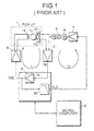
- Fig. 1 is a view for explaining an example of pick-up driving device in a conventional optical disk system.
- Fig. 2 is a view for explaining relationship between an optical disk and a pick-up.
- Fig. 3 is a view for explaining relationship between a free center and a working center of a pick-up.
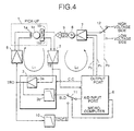
- Fig. 4 is a block diagram showing a construction of an optical disk system embodying the present invention.
- Fig. 5 shows a correlation between pick-up error signal output and a displacement of pick-up from its free center in the embodiment of Fig. 4.
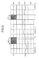
- Fig. 6 shows a correlation between a tracking error signal TE and a tracking drive signal TRD in the embodiment of Fig. 4.
- Fig. 1 is illustrative of an exemplified pick-up drive device used in a conventional optical system.
- the conventional optical system comprises a pick-up 1, a differential amplifier 2, a tracking control circuit 3, a pick-up driving circuit 5, a microcomputer 6, slide motor driving circuit 7 and a slide feeding motor 8.
- a loop L 1 is a tracking servo system and a loop L 2 is a slide servo system.
- a slide feeding servo of a conventional optical disk system uses generally a brush motor as a slide feeding motor 8 which moves the pick-up is fed across an optical disk 20 by means of a rack-and-pinion mechanism 9.
- Fig. 2 shows a relationship between the pick-up 1 of Fig. 1 and an optical disk.
- numeral 20 designates the optical disk that has a spiral information track 21 and rotates about a rotation center O 1 .
- the pick-up 1 is provided with a laser emitting light which is focused through an objective lens 1c as a small spot on the optical disk 20 for recording information into a track 21 thereof or is reflected from the track 21 through the objective lens 1c for reading the recorded information therefrom.
- the reflected light from the optical disk 20 through the objective lens 1c is also detected by paired photodiodes 1b 1 and 1b 2 shown in Fig. 1.
- the differential amplifier 2 shown in Fig. 1 detects a difference between two outputs of the paired photodiodes, which is used as a tracking error signal TE.
- the pick-up 1 may be considered to be supported by two springs 1d 1 and 1d 2 in the radial detection of the optical disk 20.
- the center axis of the pick-up 1 supported by the springs 1d 1 and 1d 2 in the balanced state is termed as "free center” that is denoted by O 2 in the shown case.
- an actuator coil la in cooperation with a magnet le is used for driving the pick-up 1. Namely, the pick-up 1 is driven in the radial direction of the optical disk 20 by the electromagnetic effect of the magnet le produced when current is applied to the actuator coil 1a. The free center of the pick-up is obtained when no current is applied to the actuator coil 1a.
- photocurrent outputs of the paired photodiodes 1b 1 and 1b 2 are converted to voltage signals by the differential amplifier 2 that outputs a differential voltage as a tracking error signal.
- a loop filter 3a provided in the tracking control circuit 3 performs proportional, integral and differential operations on the tracking error signal TE to produce a tracking drive signal TRD.
- the pick-up driving circuit 5 amplifies the tracking drive signal TRD by which an actuator 1a engaging with the pick-up 1 is energized to force a spot of laser light through the objective lens 1c to follow the information track 21 on the optical disk 20.
- the photodiodes 1b 1 , 1b 2 , the differential amplifier 2, the tracking control circuit 3a, the pick-up driving circuit 5 and the tracking actuator la constitute a tracking servo loop L1 for making the objective lens 1c to follow the information track 21.
- the output TRD of the tracking control circuit 3a passes a first low-pass filter (LPF) 3b whereby it is cleaned from noise and offset components and used for determining a deviation of the pick-up (the objective lens 1c) from its working center to produce a slide drive signal SLD.
- the cut-off frequency of the first low-pass filter 3b is within the range of 1 to 5 Hz.
- the filter produces a signal representing a mean center position of the pick-up 1 by attenuating an offset component signal (3 to 20 Hz) derived from an eccentricity of the optical disk 20.
- the slide drive signal SLD through the slide motor driving circuit 7 is fed to the slide motor 8 that drives the feeding mechanism 9 to move the entire pick-up system 1 in the radial direction of the optical disk 20.
- the photodiodes 1b 1 , 1b 2 , the differential amplifier 2, the tracking control circuit 3a, the first low-pass filter 3b, the slide motor driving circuit 7 and the slide feeding motor 8 constitute a slide servo loop L 2 that keeps the pick-up accurately centralized on the track of the optical disk.
- Fig. 3 is a diagram for explaining a relationship between the working center and the free center of the pick-up.
- a curve S 1 describes a change of radial displacement of the pick-up 1 including its eccentricity while a curve S 2 describes the working center (a change of the mean center) of the pick-up.
- the radial displacement S 1 and the working center (change of the mean center) S 2 of the pick-up 1 are defined relative to the free center O 2 of the pick-up 1, which is attainable when no current is fed to the tracking actuator coil 1a for controlling the pick-up in the radial direction.
- a mean displacement for one cycle of the eccentricity of the pick-up 1 is called “mean center” and a time-varying mean center is called "working center”.
- the first problem is that the slide feeding servo uses the low-pass filter 3b having a large time constant in its servo loop that causes a delay of several hundred milliseconds to one second in tracking a low-domain component of tracing error signal TE that is a radial displacement of the tracking actuator of the pick-up 1 from its free center through the slide feeding motor 8.
- the effect of delay of the slide feeding servo may be negligible at ordinary reproduction of the recorded data from the optical disk. But, in adjusting circuits of the optical disk system, for example, to attain tracking balance or tracking gain, there may arise such a trouble that the tracking servo loop is closed with the pick-up being out of its free center. This problem is further studied in detail for the system which is so designed that the slide is fed by 50 - 100 microns when the pick-up is displaced from its free center position by 100 microns across a compact optical disk (CD).
- CD compact optical disk
- the CD has such parameters that the width of its information track on the CD is 1.6 microns, the number of frames to be advanced for 1 second is 75, the number of frames included in one track is 8 to 9 in the center portion of the CD where the track most frequently spirals, a 1-second delay may increase the radial displacement of the pick-up on the CD by 15 microns.
- This displacement is small but enough to cause the tracking servo loop to close at a position where the pick-up is in out of its free center position if the disk has an eccentricity as shown in Fig. 3 or is secured with an eccentricity to a spindle.
- the tracking balance adjustment must be carried out on the condition that the pick-up 1 is in standstill state or with no vibration after switching OFF the tracking servo loop and the tracking gain adjustment must be conducted after the pick-up has positioned close to its free center in the radial direction for which it takes 2 to 3 seconds after switching the tracking ON.
- Fig. 4 is a block diagram for explaining an optical disk system embodying the present invention.
- numeral 10 designates a second low-pass filter and numerals 11 and 12 designate change-over switches.
- the other components are the same as those of the conventional optical disk system of Fig. 1 and are, therefore, omitted from the scope of explanation.
- a tracking drive signal TRD passes the second low-pass filter 10 having a cut-off frequency of about 300 - 600 Hz.
- the filter does not attenuate an offset component signal (3 to 20 Hz) derived from an eccentricity of the optical disk, and therefore produces a signal TRDFS that indicates an actual relative position of the pick-up.
- a slide servo loop L 2 is provided with a microcomputer 6.
- An output of a first low-pass filter 3b or an output of the second low-pass filter 10 through an input selector switch 11 of an A/D (analog-to-digital) converter is inputted to an A/D input port incorporated in the microcomputer 6.
- the microcomputer 6 recognizes the current state of the pick-up 1 according to the signals SLD (a mean center position) and TRDFS (an actual position including an offset component), which have been received through the A/D input port.
- a slide motor 8 is a three-phase direct-current motor and a slide motor driving circuit 7 is a three-phase full-wave driver.
- the slide motor driving circuit 7 receives a control signal P 1 for starting or stopping the slide motor and a direction changing signal P 2 for changing the rotating direction of the slide motor, which is outputted from an output port of the microcomputer 6.
- the switch 12 selects a torque command - either one of two (high and low) control voltages.
- the low voltage signal is selected to apply micro-feed a slide for reproducing the recorded information and the high voltage signal is selected to apply fast feeding for searching the record.
- the microcomputer 6 contains a software that is a control means for controlling feeding a slide according to the signals SLD and TRDFS. It also contains (not shown in the figure ) routines for determining a tracking-OFF time, disk rotation frequency T, time of 1/2T and time of 3/4T, a table of values for determining a relative value of displacement of the pick-up 1 from its free center position according to the signal TRDFS and a timer.
- the first case is that the free center of the pick-up in the radial direction of an optical disk is controlled by finely feeding the slide when the switch 12 is set in the low voltage position.
- the A/D input selector switch 11 is switched to the A/D input port of the microcomputer 6 to feed thereto the slide drive signal SLD.
- the microcomputer receives the signal SLD at a specified interval.
- the A/D input selector switch 11 is switched to the position for selecting a signal TRDFS indicating an actual position of the pick-up 1, in which an eccentricity of the optical disk is included.
- the microcomputer 6 When the pick-up positions above the center portion of the optical disk, the microcomputer 6 receives the signal TRDFS from the A/D input port at intervals of several seconds for one rotation period of the optical disk which corresponds to a period of about 120 milliseconds from point A to point B shown in Fig. 3. Consequently, an eccentricity of the optical disk is roughly estimated from a maximal value and a minimal value of the A/D inputs and an average center position of the pick-up 1 is also roughly estimated from an average of the A/D inputs.
- Fig. 5 is illustrative of why a rough eccentricity of the optical disk and a mean center portion of the pick-up 1 can be estimated.
- the output level of a radial error signal of the pick-up 1 decreases as the displacement of the pick-up 1 from its free center increases.
- Variation of two photodiodes 1b 1 and 1b 2 ( Fig. 1 ) engaging with the pick-up 1 causes a change of the error-signal output level by 3 - 4 dB. Therefore, an output level of the tracking error signal TE does not always correspond accurately to a displacement of the pick-up from its free center.
- the tracking error signal TE appears only in the positive direction but there may be a zero-crossing point on the tracking error signal if an eccentric component of the optical disk is added. Consequently, the displacement of the pick-up 1 from its free center can be calculated at the above-mentioned error of 3 - 4 dB if the pick-up 1 is relatively close to its free center.
- the second case is that the free center of the pick-up 1 is controlled in the radial direction by switching ON and OFF the tracking control.
- the tracking error signal from the pick-up 1 is amplified by the differential amplifier 2 and enters into the tracking control circuit 3 that produces a tracking drive signal TRD and produces a slide driving signal SLD through the low-pass filter 3b.
- the signal TRD is applied to the driving circuit 5 that drives a tracking actuator 1a in the pick-up 1.
- the signal TRD through a low-pass filter 10 appears as a signal TRDFS that is applied by the selector switch 11 to the A/D input port of the microcomputer 6.
- the microcomputer 6 can monitor the state of the signal TRD through its A/D input port and can control the tracking control circuit 3 by applying thereto a control command.
- the microcomputer 6 samples signals TRD for one period from the A/D input port and determines therefrom an eccentricity of the optical disk currently chucked.
- Sampling is repeated if the mean center of the pick-up is apart from the free center.
- the microcomputer 6 turns OFF the tracking control and waits for the time of 1/2T- ⁇ (T is a rotation frequency and ⁇ is a desired offset time).
- T is a rotation frequency and ⁇ is a desired offset time.
- the microcomputer 6 judges whether the tracking actuator 1a exists at its free center or not.
- the aligning operation is finished when the pick-up 1 locates at the free center.
- Fig. 6 shows data obtained in the experiments made by using 4-channel digital storage oscilloscope. Channels CH 1 and CH 3 show the observed data and channels CH 2 and CH 4 has no input.
- the microcomputer 6 turns OFF the tracking control at the time T1 when the pick-up is shifted close to its free center position, then it waits for the time of 3/4T- ⁇ and turns ON the tracking control and judges whether the pick-up 1 exists at the free center position.
- the microcomputer 6 After making sure of the tracking actuator la being in its free center position, the microcomputer 6 sends exciting current to the tracking actuator 1a to move by kick the pick-up 1 in the radial direction.
- the microcomputer 6 operates the slide motor 8 to slightly rotate to bring the pick-up 1 close to the free center (otherwise the kick operation causes the pick-up to move over the preset value). In this case, the microcomputer 6 maintains the slide motor being excited during the kick operation in order to assure fast execution of the next kick of the pick-up.
- the system according to the present invention can detect a linear velocity with an increased accuracy owing to that kicking from the bottom or the top of the eccentricity across the pick-up free center can attain a rather increased accuracy as compared with kicking from the pick-up free center.
- the linear velocity is ordinary determined in such manner that the pick-up is first kicked by a specified number of tracks from a current address and then a linear velocity is determined by calculation from an address after the kick.
- the above-described embodiment of the present invention is capable of bringing the pick-up quick and accurately to the free center by using the tracking actuator la engaging the pick-up 1.
- Application of this system assures saving the initial operation time of a CD player or a CD drive which performs self-alignment in the initial operation stage.
Landscapes
- Optical Recording Or Reproduction (AREA)
- Moving Of The Head For Recording And Reproducing By Optical Means (AREA)
Claims (4)
- Optisches Plattensystem, umfassend:gekennzeichnet durcheinen Pickup, der gegenüber einer optischen Platte angeordnet ist, die eine Spiralspur (21) mit darauf gespeicherten optisch reproduzierbaren Informationen aufweist, und der zum Wiedergeben der auf der Spur (21) der optischen Platte gespeicherten Informationen und zum Erfassen der Informationen an der Spurposition verwendet wird;eine Bewegungseinrichtung (8) zum Bewegen des Pickups in einer radialen Richtung der optischen Platte (20);eine erste Erfassungseinrichtung (1b1, 1b2, 2), um aus dem Spurpositionsinformationssignal einen relativen Lagefehler des Pickups (1) relativ zur Spur (21) zu erfassen;eine Pickup-Antriebssignal-Erzeugungseinrichtung (3) zum Erzeugen eines Pickup-Antriebssignals TRD zum Antreiben des Pickups, indem die Ausgabe der ersten Erfassungseinrichtung (1b1, 1b2, 2) mit einem Filter (3a) verarbeitet wird;eine zweite Erfassungseinrichtung zum Erfassen einer mittleren Mittellage des Pickups (1), indem das Pickup-Antriebssignal mit einem Tiefpassfilter (3b) verarbeitet wird,eine dritte Erfassungseinrichtung (10) zum Erfassen einer gegenwärtigen Lage des Pickups (1) relativ zur Spur (21), indem das Pickup-Antriebssignal TRD verarbeitet wird, während die erste Erfassungseinrichtung (1b1, 1b2, 2) den relativen Lagefehler des Pickups relativ zu der Spur (21) erfasst;eine Einrichtung (11) zum Auswählen zwischen einer Ausgabe der zweiten Erfassungseinrichtung und einer Ausgabe der dritten Erfassungseinrichtung (10); undeine Steuereinrichtung (6) zum Steuern der Bewegungseinrichtung (8), um den Pickup (1) in der radialen Richtung der optischen Platte (20) gemäß einer Ausgabe der dritten Erfassungseinrichtung (10) zu verschieben.
- Optisches Plattensystem nach Anspruch 1, dadurch gekennzeichnet, dass die Steuereinrichtung (6) aus den Ausgaben der dritten Erfassungseinrichtung einen Maximalwert, einen Minimalwert und einen Durchschnittswert eines relativen Lagefehlers des Pickups relativ zur optischen Platte für eine Umdrehung der Platte, aus dem Maximalwert und dem Minimalwert eine Größenordnung der Exzentrizität der Platte (20), und einen Betriebsmittelpunkt des Pickups (1) bestimmt, und die Verschiebungseinrichtung veranlasst, den Pickup (1) zu dem Betriebsmittelpunkt zu bewegen.
- Optisches Plattensystem nach Anspruch 1, dadurch gekennzeichnet, dass die Pickup-Antriebssignal-Erzeugungseinrichtung (3) gesteuert wird, gemäß externer Befehle ein- und ausgeschaltet zu werden, wobei die Steuereinrichtung (6) die Pickup-Antriebssignal-Erzeugungseinrichtung nach Ablauf der Zeit 1/2 T-α oder 3/4 T-α einschaltet, wobei T eine Umdrehungszeit und α eine Ausgleichszeit ist.
- Optisches Plattensystem nach Anspruch 1, dadurch gekennzeichnet, dass die Steuereinrichtung (6) eine vierte Erfassungseinrichtung (5) zum Erfassen einer Lineargeschwindigkeit einer optischen Platte (20) und eine Stoßschaltkreiseinrichtung (1a, 1e) zum zwangsweisen Antreiben des Pickups in der Radialrichtung der Platte (20) aufweist, um eine vorbestimmte Verschiebung zu gewährleisten.
Applications Claiming Priority (3)
| Application Number | Priority Date | Filing Date | Title |
|---|---|---|---|
| JP7771895 | 1995-04-03 | ||
| JP77718/95 | 1995-04-03 | ||
| JP07077718A JP3129629B2 (ja) | 1995-04-03 | 1995-04-03 | 光ディスク装置 |
Publications (2)
| Publication Number | Publication Date |
|---|---|
| EP0736862A1 EP0736862A1 (de) | 1996-10-09 |
| EP0736862B1 true EP0736862B1 (de) | 2001-08-16 |
Family
ID=13641677
Family Applications (1)
| Application Number | Title | Priority Date | Filing Date |
|---|---|---|---|
| EP96102111A Expired - Lifetime EP0736862B1 (de) | 1995-04-03 | 1996-02-13 | System für optische Platten |
Country Status (4)
| Country | Link |
|---|---|
| US (1) | US5751673A (de) |
| EP (1) | EP0736862B1 (de) |
| JP (1) | JP3129629B2 (de) |
| DE (1) | DE69614430T2 (de) |
Families Citing this family (3)
| Publication number | Priority date | Publication date | Assignee | Title |
|---|---|---|---|---|
| US6549492B1 (en) | 1999-06-30 | 2003-04-15 | Oak Technology, Inc. | Method and apparatus for run-out correction in a disk drive |
| JP4551597B2 (ja) * | 2000-11-08 | 2010-09-29 | 株式会社ソニー・コンピュータエンタテインメント | 光ディスク装置、その制御方法、およびこの制御方法をコンピュータに実行させるプログラム |
| WO2011104756A1 (ja) | 2010-02-25 | 2011-09-01 | 三菱電機株式会社 | ディスク装置 |
Family Cites Families (8)
| Publication number | Priority date | Publication date | Assignee | Title |
|---|---|---|---|---|
| JPS6226644A (ja) * | 1985-07-29 | 1987-02-04 | Hitachi Ltd | 光学式情報記録再生装置 |
| US4907214A (en) * | 1985-12-18 | 1990-03-06 | Kabushiki Kaisha Toshiba | Eccentricity correction apparatus for an optical disk device |
| US5208792A (en) * | 1987-05-29 | 1993-05-04 | Matsushita Electric Industrial Co., Ltd. | Recording and reproducing apparatus using opto-magneto media |
| JPH01173324A (ja) * | 1987-12-28 | 1989-07-10 | Toshiba Corp | 情報処理装置 |
| EP0325434B1 (de) * | 1988-01-19 | 1994-10-12 | Fujitsu Limited | Spurzugangsregelsystem |
| JPH0460974A (ja) * | 1990-06-26 | 1992-02-26 | Pioneer Electron Corp | トラッキングサーボ装置 |
| EP0565751A1 (de) * | 1992-04-14 | 1993-10-20 | Pioneer Electronic Corporation | Optisches Aufzeichnungsverfahren und Gerät dafür |
| JPH05325210A (ja) * | 1992-05-26 | 1993-12-10 | Pioneer Electron Corp | トラックジャンプ制御装置 |
-
1995
- 1995-04-03 JP JP07077718A patent/JP3129629B2/ja not_active Expired - Fee Related
-
1996
- 1996-01-17 US US08/587,929 patent/US5751673A/en not_active Expired - Lifetime
- 1996-02-13 DE DE69614430T patent/DE69614430T2/de not_active Expired - Lifetime
- 1996-02-13 EP EP96102111A patent/EP0736862B1/de not_active Expired - Lifetime
Also Published As
| Publication number | Publication date |
|---|---|
| JPH08279169A (ja) | 1996-10-22 |
| JP3129629B2 (ja) | 2001-01-31 |
| US5751673A (en) | 1998-05-12 |
| DE69614430T2 (de) | 2002-05-02 |
| EP0736862A1 (de) | 1996-10-09 |
| DE69614430D1 (de) | 2001-09-20 |
Similar Documents
| Publication | Publication Date | Title |
|---|---|---|
| JP3546549B2 (ja) | 光学式ディスク駆動装置および方法 | |
| JP2656371B2 (ja) | 光ディスク装置 | |
| US20080037390A1 (en) | Read/write position controller for optical pickup | |
| US6633522B2 (en) | Focus pull-in method and optical disk device | |
| EP0367094B1 (de) | Optischer Plattenspieler | |
| US6252835B1 (en) | Apparatus for automatically adjusting focus offset and method thereof in a disc player | |
| US5621709A (en) | Tracking servo apparatus | |
| US5218453A (en) | Optical disc access control apparatus | |
| EP0736862B1 (de) | System für optische Platten | |
| JP2947095B2 (ja) | 光ディスク装置及びアクセス制御方法 | |
| US4979048A (en) | Apparatus for and method of stop control for a spindle motor in a disk player | |
| JPH076372A (ja) | 光ピックアップ装置およびそのフォーカス制御方法 | |
| JPS6120715Y2 (de) | ||
| JPH0510277Y2 (de) | ||
| US6801480B2 (en) | Optical disk drive apparatus capable of braking the optical head at half track short of target track | |
| JPH02289925A (ja) | コンパチブルディスクプレーヤにおけるディスクサイズ判定装置 | |
| JP3663780B2 (ja) | 対物レンズ駆動装置及び光ピックアップ装置及び光ディスク装置 | |
| KR100200344B1 (ko) | 광학 시스템에서의 포커스 풀-인 방법 | |
| JP2002015423A (ja) | 光ディスク装置 | |
| CN100440328C (zh) | 光盘装置 | |
| JP2600782B2 (ja) | 光ビームの傾き補正装置 | |
| JP2003045045A (ja) | 光ディスク装置 | |
| KR100223214B1 (ko) | 광디스크재생장치에서 광디스크의 종류를 판단하는 방법 | |
| JPH02281432A (ja) | 光学的情報再生装置の光ディスク検出装置 | |
| JPH06290467A (ja) | 光ディスクドライブシステム |
Legal Events
| Date | Code | Title | Description |
|---|---|---|---|
| PUAI | Public reference made under article 153(3) epc to a published international application that has entered the european phase |
Free format text: ORIGINAL CODE: 0009012 |
|
| AK | Designated contracting states |
Kind code of ref document: A1 Designated state(s): DE GB |
|
| 17P | Request for examination filed |
Effective date: 19970207 |
|
| 17Q | First examination report despatched |
Effective date: 19991117 |
|
| GRAG | Despatch of communication of intention to grant |
Free format text: ORIGINAL CODE: EPIDOS AGRA |
|
| GRAG | Despatch of communication of intention to grant |
Free format text: ORIGINAL CODE: EPIDOS AGRA |
|
| GRAH | Despatch of communication of intention to grant a patent |
Free format text: ORIGINAL CODE: EPIDOS IGRA |
|
| GRAH | Despatch of communication of intention to grant a patent |
Free format text: ORIGINAL CODE: EPIDOS IGRA |
|
| GRAA | (expected) grant |
Free format text: ORIGINAL CODE: 0009210 |
|
| AK | Designated contracting states |
Kind code of ref document: B1 Designated state(s): DE GB |
|
| REF | Corresponds to: |
Ref document number: 69614430 Country of ref document: DE Date of ref document: 20010920 |
|
| REG | Reference to a national code |
Ref country code: GB Ref legal event code: IF02 |
|
| PLBE | No opposition filed within time limit |
Free format text: ORIGINAL CODE: 0009261 |
|
| STAA | Information on the status of an ep patent application or granted ep patent |
Free format text: STATUS: NO OPPOSITION FILED WITHIN TIME LIMIT |
|
| 26N | No opposition filed | ||
| PGFP | Annual fee paid to national office [announced via postgrant information from national office to epo] |
Ref country code: GB Payment date: 20100202 Year of fee payment: 15 Ref country code: DE Payment date: 20100226 Year of fee payment: 15 |
|
| GBPC | Gb: european patent ceased through non-payment of renewal fee |
Effective date: 20110213 |
|
| REG | Reference to a national code |
Ref country code: DE Ref legal event code: R119 Ref document number: 69614430 Country of ref document: DE Effective date: 20110901 |
|
| PG25 | Lapsed in a contracting state [announced via postgrant information from national office to epo] |
Ref country code: GB Free format text: LAPSE BECAUSE OF NON-PAYMENT OF DUE FEES Effective date: 20110213 |
|
| PG25 | Lapsed in a contracting state [announced via postgrant information from national office to epo] |
Ref country code: DE Free format text: LAPSE BECAUSE OF NON-PAYMENT OF DUE FEES Effective date: 20110901 |