EP0736848A2 - Vorrichtungen zur Scheidung von Münzen, Wertmarken und dergleichen und automatische Zahlungsgeräte - Google Patents
Vorrichtungen zur Scheidung von Münzen, Wertmarken und dergleichen und automatische Zahlungsgeräte Download PDFInfo
- Publication number
- EP0736848A2 EP0736848A2 EP96107719A EP96107719A EP0736848A2 EP 0736848 A2 EP0736848 A2 EP 0736848A2 EP 96107719 A EP96107719 A EP 96107719A EP 96107719 A EP96107719 A EP 96107719A EP 0736848 A2 EP0736848 A2 EP 0736848A2
- Authority
- EP
- European Patent Office
- Prior art keywords
- disc
- coins
- tokens
- cells
- frame
- Prior art date
- Legal status (The legal status is an assumption and is not a legal conclusion. Google has not performed a legal analysis and makes no representation as to the accuracy of the status listed.)
- Withdrawn
Links
Images


Classifications
-
- G—PHYSICS
- G07—CHECKING-DEVICES
- G07B—TICKET-ISSUING APPARATUS; FARE-REGISTERING APPARATUS; FRANKING APPARATUS
- G07B15/00—Arrangements or apparatus for collecting fares, tolls or entrance fees at one or more control points
- G07B15/06—Arrangements for road pricing or congestion charging of vehicles or vehicle users, e.g. automatic toll systems
- G07B15/066—Arrangements for road pricing or congestion charging of vehicles or vehicle users, e.g. automatic toll systems being coin-operated
-
- G—PHYSICS
- G07—CHECKING-DEVICES
- G07D—HANDLING OF COINS OR VALUABLE PAPERS, e.g. TESTING, SORTING BY DENOMINATIONS, COUNTING, DISPENSING, CHANGING OR DEPOSITING
- G07D3/00—Sorting a mixed bulk of coins into denominations
- G07D3/02—Sorting coins by means of graded apertures
- G07D3/06—Sorting coins by means of graded apertures arranged along a circular path
-
- G—PHYSICS
- G07—CHECKING-DEVICES
- G07D—HANDLING OF COINS OR VALUABLE PAPERS, e.g. TESTING, SORTING BY DENOMINATIONS, COUNTING, DISPENSING, CHANGING OR DEPOSITING
- G07D3/00—Sorting a mixed bulk of coins into denominations
- G07D3/12—Sorting coins by means of stepped deflectors
- G07D3/128—Rotary devices
-
- G—PHYSICS
- G07—CHECKING-DEVICES
- G07D—HANDLING OF COINS OR VALUABLE PAPERS, e.g. TESTING, SORTING BY DENOMINATIONS, COUNTING, DISPENSING, CHANGING OR DEPOSITING
- G07D3/00—Sorting a mixed bulk of coins into denominations
- G07D3/14—Apparatus driven under control of coin-sensing elements
-
- G—PHYSICS
- G07—CHECKING-DEVICES
- G07D—HANDLING OF COINS OR VALUABLE PAPERS, e.g. TESTING, SORTING BY DENOMINATIONS, COUNTING, DISPENSING, CHANGING OR DEPOSITING
- G07D9/00—Counting coins; Handling of coins not provided for in the other groups of this subclass
- G07D9/008—Feeding coins from bulk
Definitions
- the present invention relates to devices for the separation of coins, tokens and the like, intended to be integrated, for example, into an automatic payment device.
- the present invention also relates to such devices.
- EP-A-0 420 921 discloses an automatic payment device in which a separating disc receives on its upper face the coins or tokens to be separated and comprises at its periphery cells intended to each receive a coin or token.
- the cells open through the upper face of the disc. They also open opposite a fixed peripheral wall forming a lateral guide wall for the coins or tokens driven in rotation by the cells.
- the pieces slide on a fixed supporting surface. They pass within the field of action of a detector. They then reach a passage opening towards a circular display located next to the rotating disc.
- the passage opening is configured according to one or the other of two different configurations leading the coins or tokens either to a peripheral compartment of the display or to a central compartment.
- a presentation region comprising a central compartment and a peripheral compartment is in a position to receive the coins or tokens coming from the separating disc at through the passage opening
- another presentation region comprising another peripheral compartment and another central compartment is in a presentation position, in which the coins or tokens corresponding to a previous payment are visible to the users
- a third presentation region, comprising the third peripheral compartment and the third central compartment is in a position for transmitting the coins or tokens to a later station, for example a coin or token storage chest, a return device for the coins or tokens not accepted, etc.
- a delivery bar is intended to prevent the superimposed parts from reaching the detector. But as the delivery bar must be placed at a sufficient distance from the bearing surface to allow the passage of the thickest parts, this bar is in some cases incapable of preventing the simultaneous passage of two thin parts which would have lodged in the same cell. In any case, if the second part protrudes from the upper surface of the disc, it is dangerous to try to dislodge it by the delivery bar as this may cause blockage and damage. This problem cannot be solved by thinning the disc as this would allow a thin piece to pass between the upper surface of the disc and the delivery bar.
- the presentation device is quite bulky since its diameter is greater than that of the separation device and it therefore more than doubles the surface necessary to accommodate the two devices side by side, compared to that which 'would require the separation device alone.
- the object of the present invention is to remedy these drawbacks.
- a device for the separation of coins, tokens or the like comprising a rotary disc provided with successive peripheral cells, for receiving the coins, tokens or the like, means for sending the pieces, tokens or the like on the upper surface of the disc so that they are distributed in the cells when the disc is in a service position in which said disc is generally located in a plane forming a first angle with the vertical direction, and a motor having an output shaft connected to the disc for driving the rotating disc, in which the disc is supported in rotation by a mount to which is fixed, at least indirectly, the motor housing, and said mount is articulated to a frame of the device to be movable between a service position in which the disc is in the service position, and a purge position in which the disc is generally located in a plane forming with the vertical direction a second angle smaller than the first angle.
- the disc When the mount is in the purge position, the disc is in a plane close to the vertical, and it easily gets rid, by gravity, of foreign bodies which may be on it.
- the mobility of the frame does not involve any particular complication of the structure.
- an actuator is provided to move the frame in at least one direction of its movement between the service and purge positions, the other direction of movement being able for example to be ensured by gravity, it is possible to shake the frame and the disc using the actuator to promote the fall of foreign bodies.
- the successive cells open opposite a fixed lateral guide wall and through the upper face of the disc mobile, the lateral guide wall comprising a notch for splitting the coins, tokens or the like, this notch being open towards the mobile member and comprising an inclined bottom which, when it is traversed in the direction of travel of the cells opposite the notch goes from a lower region situated higher than a bearing face of the coins, tokens or the like, but lower than the upper face of the movable member, to an upper region further from the bearing face.
- the upper region of the inclined bottom of the notch is at a distance at least equal, or even greater than that of the upper surface of the movable member relative to the load-bearing surface on which the parts slide.
- the speed at which the coins or tokens are driven is high, the upper region of the bottom of the notch can be relatively close to the bearing surface, the bottom of the notch then having the role of a springboard intended to blow the piece to a height greater than that of the upper region of the bottom of the notch.
- an automatic payment device comprising a separator comprising a separation device as described above, the disc being provided with cells, for receiving coins or tokens and being movable in rotation for scroll the coins or tokens in the field of action of a detector then next to at least one passage opening towards a display unit which comprises partitions to define several regions of presentation of the coins or tokens, and means of partitioning drive to cyclically pass these regions through a position for receiving coins or tokens from the separator and a position for transmitting coins or tokens to a next station, such as a collection chest, in which the display is a annular display arranged around the disc, the drive means causing the cyclic displacement of the presentation regions tion around the disc.
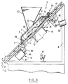
- the payment apparatus comprises a separator 1 in turn comprising a disc 2 which, in the service position shown in Figures 1 to 3, is in a plane P ( Figure 3) forming an angle A of approximately 45 ° with the vertical direction.
- the disc 2 has on its periphery cells 3 which open through an upper face 4 of the disc 2 and through its peripheral edge 6, opposite a lateral guide wall 7 which is integral with a frame 8 of the device.
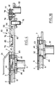
- the bottom of the cells 3 is closed by a support face 9 for the coins or tokens, constituted by the upper face of a bottom plate 11 (FIG. 3).
- the disc 2 is connected in rotation to the output shaft 12 of an electric motor 13, the casing 14 of which is fixed to the underside of the plate 11.
- the plate 11 belongs to a frame 16 which is connected to the frame 8 of the apparatus by a hinge 17 which is adjacent to an upper region of the disc.
- the axis 18 of the articulation 17 is substantially horizontal and parallel to the plane P.
- the mount 16 is locked by a locking device 19 diametrically opposite the articulation 17, and which secures the frame 16 with the frame 8 of the device.
- the separator 1 further comprises a cover 21 crossed by the outlet orifice 22 of a hopper 23 into which the users throw coins, tokens or the like.
- the cover 21 is connected to the frame 8 of the device by a hinge 24 which is close to the hinge 17 and the upper region of the disc to allow the cover 21 and the hopper 23 to be raised when it is necessary to access disc 2, especially for maintenance.
- the coins 26 (figure 1) which are thrown into the hopper 23 meet a central conical reinforcement 27 (figures 2 and 3) of the disc 2 then move towards the lower region 28 of the disc 2, being prevented from falling lower by the cover 21.
- Some parts are housed in the cells 3 which are in the lower region 28 of the disc and these parts are driven upwards in the direction of the arrow F in FIG. 2 by the rotation of the disc 2. This rotation also brings in the lower position new cells in which other parts are housed and so on until all the parts corresponding to the payment made are driven upwards by the cells 3 in the direction of the arrow F .
- the pieces pass through a splitting station 29 (FIG. 2) then into the field of action of a detector 31 which is only shown in dashed lines in FIG. 2 and which is for example of the type described in EP-A-0 420 921, in which case it is placed above of the path of the coins or tokens and eccentrically with respect to this path, then finally by a station 32 for distributing the coins or tokens to a display stand 33 which will be described in detail below.
- the splitting station 29 comprises (FIGS. 5, 6, 7) a notch 34 which is formed in the inner peripheral face and in the upper face of the lateral guide wall 7.
- the notch 34 is therefore open towards the disc 2 whose only the upper face 4 is represented by a dashed line in FIGS. 5 and 6.
- the notch 34 has a substantially flat inclined bottom 36.
- the low region 37 of the bottom 34 is located higher than the carrier face 9 of the carrier surface 11 and lower than the upper face 4 of the disc 2.
- the upper region 38 is further from the carrier face 9 than the lower region 37. In the example shown, the upper region 38 is even much further from the carrier face 9 than the upper face 4 of the disc.
- the lower region 37 of the notch widens radially and then the upper region 38 shrinks radially.
- the notch 34 is located opposite an ascending region of the path of the cells, and more particularly in the first half of the upward path of the cells, so that the carrier face 9 and the upper face of the disc lean towards lateral guide wall 7 where the notch 34 is located.
- a discharge blade 39 is fixed to the cover 21 (see FIG. 2 and also FIGS. 14 and 15) so as to be in contact or almost in contact with the upper face 4 of the disc 2 at a location which is located after the notch 34 relative to the direction of movement of the cells, symbolized by the arrow F.
- the relative situation of the notch 34 and the discharge blade 39 is visible in FIG. 2 and in FIG. 13.
- the discharge blade 39 is intended for prevent the passage of objects which would significantly protrude with respect to the upper face 4 of the disc 2.
- the delivery blade 39 is made elastic to avoid mechanical impact with said objects.
- the main purpose of this station is to prevent two causes of malfunction: the presence of two superimposed parts in the same cell 3 of the disc 2 ( Figure 8); and the presence of a part 41 or other object resting on the upper face 4 of the disc 2 as shown in FIG. 13.
- the distance between the delivery blade 39 and the carrying face 9 must be sufficient to allow the passage of the thickest parts under the blade 39.
- the distance between the blade 39 and the upper face 4 of the disc 2 must be small enough to prevent the passage of the thinnest parts likely to be received by the device.
- the disc 2 must have a certain minimum thickness that cannot be reduced and this minimum thickness allows two thin pieces to be driven in superposition in the same cell 3 ( Figure 8).
- the superimposed part 41 traverses the bottom of the notch 34 and thus reaches the upper region 38 of this bottom, which takes it off from the underlying part 42 and raises it until the point 43 of the superimposed part 41 on which the edge of the cell 3 rests to push the part 41 in the direction F, passes above the upper surface 4 of the disc ( Figures 10 and 11). Therefore, the superimposed part 41 escapes from the cell 3 ( Figure 12). As this happens in an ascending region of the path of the cells, the superimposed part 41 tends to go back relative to the disc and go to be housed in the next cell if it is free.
- the discharge blade 39 (FIG. 13) avoids this risk and stops the part 41 before it reaches the detector.
- the blade 39 has a shape of deflector which deflects the part 41 towards the center of the disc, as a result of which the part 41 can fall towards the lower region of the disc and occupy a new cell.
- the detector 31 recognizes the coin, or on the contrary detects that the coin or other token which has been introduced does not correspond to any known type, unless it gives an answer of doubt, a situation which will be studied later.
- the detector 31 is placed above the end of the upward path of the cells.
- the distribution station 32 which follows is mainly placed in the first half of the path down from the cells.
- the distribution station 32 (FIG. 2) includes a passage opening 43 for the parts which, according to the result of the detection operated by the detector 31, are considered to be good, and, after the opening 43 relative to the direction of rotation F of the disc 2, a passage opening 44 for the parts which have been recognized as not valid by the detector 31.
- the openings 43 and 44 are made through the lateral guide wall 7 opposite a recess 46 or respectively 47 formed in the carrying face 9. Each recess 46 or 47 communicates with the passage opening 43 or 44 associated by a respective tunnel 48 (FIG. 4) formed in the plate 11.
- a hatch 49 fixed to the core plunger of an electromagnet 51 for actuating this flap is movable so as to be able to assume a release position (FIGS.
- the tunnel 48 has an orientation oblique to the local radial direction so that the path of the parts from the recess 46 to the display is generally descending due to the inclination of the plane P.
- the flap 49 closes the recess 46 so that the upper face 53 of the flap 49 completes without significant discontinuity the carrying face 9 of the plate 11.
- the electromagnet 51 is controlled to place the hatch 49 in the closed position for the passage of a cell 3 of the disc 2 when the detection operated by the detector 31 has revealed that the part 52 is not of a model accepted by the device or that Exhibit 52 has not been identified with certainty.
- a part such as 52 continues its path along the lateral guide wall 7 until it meets the second recess 47, which is equipped, in the same way as the first recess with a hatch 50 ( in the closed position in Figure 2) controlled by an electromagnet.
- this second hatch 50 is open and the room falls there to leave towards the display 33 through the passage opening 44 after having passed through a tunnel similar to the tunnel 48 of FIG. 4. If the room is doubtful, the hatch 50 of the second recess 47 is closed and the part is again driven by the disc 2 towards the detection means.
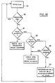
- the step 94 "detection” includes detection by the detector 31.
- the test 96 checks whether the display 33 is ready or if, on the contrary, it is moving. In the second case, the part is returned to detection (step 94), that is to say that the two doors 49, 50 are kept closed. If the display unit 33 is ready, the result of the detection is subjected to a test 97. If the part is recognized as acceptable, the flap 49 opens and the part can pass through the opening 43 towards the display 33. Otherwise, the result of the detection is subjected to a second test "part refused ? " 98.
- the flap 49 is kept closed and the flap 50 is open to allow the piece to exit through the opening 44 towards the display 33. If the piece is not not recognized with certainty as a different part from the accepted parts, we carry out a test "first pass?" 99. During this test, it is checked whether a questionable part, that is to say neither accepted nor refused, has already passed into the field of action of the detector 31 by occupying the same cell 3 of the disk 2. This is achievable by knowing the number of disc cells and counting the cyclic disturbances created by the passage of the cells in the detector field.
- step 101 If the answer is no, in other words if the questionable coin has just made its first pass in the detector field, its position in the cycle is memorized (step 101), and it is returned to the detector's field of action (step 94) to give it a new chance of identification. It is precisely the memorization step 101 which then makes it possible to count the passages of cells under the detector 31 until the second passage of the part. If the piece is positively accepted or refused on the second pass, this memorization is then erased. If, on the second pass, the part is again dubious, it is sent to the passage opening 44 ("NO" output in test 99).
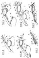
- the display 33 is an annular display surrounding the separator 1 and it comprises three presentation regions 54a, 54b and 54c distributed angularly around the axis of the disc 2 (FIG. 2).
- Each presentation region 54a, 54b, 54c includes two compartments 56 and 57 for the accepted coins and respectively for the rejected coins.
- the compartments have shapes in a circle sector.
- a central rib 58 of generally circular shape, separates the compartments 56 located radially outside and the compartments 57 located radially inside.
- Two other ribs of generally circular shape 59 and 61 limit the compartments radially outwards, and respectively radially inward the compartments 57.
- the ribs 58, 59 and 61 are integral with the frame 8 of the device, likewise a plate 62 on which the parts rest and can slide.
- the inner peripheral 61 and central 58 ribs have two passages 63 and 64 aligned for the passage of the accepted pieces, aligned opposite the opening 43 along the desired oblique path relative to the local radial direction from the recess 46 to the radially external compartments. 57 intended for accepted parts.
- the radially inner rib 61 has, after passage 63 relative to the direction of travel F of the cells, a second passage 64 opposite the passage opening 44 for the passage of the parts from the recess 47 in the radially compartments 57 interiors intended for rejected parts.
- the presentation regions 54a, 54b and 54c are separated by partitions.
- partitions There are in particular three external partitions 68 which separate the radially external compartments 56 from one another and extend between the central rib 58 and the external peripheral rib 59.
- the partitions also comprise three internal partitions 69 which separate one from the other, the radially inner compartments 57 and extend between the central rib 58 and the inner peripheral rib 61.
- the partitions 69 are of relatively great circumferential length and are each crossed by a passage 71.
- the partitions 68 and 69 are fixed to the underside of a transparent cover 72 which is of annular shape and of which, for reasons of clarity, only a portion of the radially outer edge has been shown (by small crosses).
- 73 located radially beyond the outer peripheral rib 59, and part of the edge radially inner 74 which is roughly adjacent to the inner peripheral rib 61.
- the cover 72 rests on three support rollers 76 with a radial axis, supported in rotation by the frame 8, and it is centered between three centering rollers 77 resting on the outer peripheral edge 73 of the cover 72.
- the three carrier rollers 76 are free to rotate, as are two of the centering rollers 77, which are supported by the frame 8 of the device.
- the third centering roller 77 (top right of FIG. 2) is supported in rotation by a yoke 78 which is pushed by a spring 79 so that the roller 77 tends to bear elastically both against the peripheral edge 73 of the cover 72 and against the output shaft 81 of an electric motor 82 (FIG. 4) for rotating the cover 72 around the axis of the disc.
- the motor 82 is excited to rotate the cover 72 by a third of a turn in the direction of the arrow F each time a payment has been made.
- the cover 72 is stopped, as shown in FIG. 2, there is a partition 68 which is located just before the passage 64 provided in the central rib 58, and a partition 69 which is stopped just before the passage 67 through the inner peripheral rib 61, while the passage 71 of the same partition 69 extends obliquely downward, relative to the local radial direction, from the passage 63 through the inner peripheral rib to the passage 64 through the central rib 58.
- the presentation region (54a in FIG. 2) which is limited at the rear by the two partitions 68 and 69 located in the position which we have just spoken of, that is to say just before passage 64 and respectively the passage 67 is in a position known as receiving the parts. Indeed, if a part is authorized to leave the separator through the passage opening 43, it will reach by gravity the radially outer compartment 56 of the region 54a after having crossed the passage 63, the corridor 71 and the passage 64. more, a part authorized to leave the separator through the opening 44 as described above reaches the radially inner compartment 57 after having crossed the passage 67.
- another presentation region, 54b is in the presentation position, in which one can observe the coins contained in the two compartments 56 and 57 of this region, coins which correspond to the previous payment.
- the third presentation region 54c is in the transmission position: the partitions 68 and 69 which delimit the rear of this region (top left of FIG. 2) have pushed the pieces corresponding to an even previous payment.
- orifices 83 and 84 respectively leading to a collection chest and to a means for returning the pieces refused to the user.
- the orifice 83 can be closed, for example if the corresponding trunk is full, in which case the parts will be evacuated through a second orifice 86 leading for example to another trunk.
- the motor 82 is controlled to rotate the cover 72 a third of a turn, so that the region of the presentation which was in the reception position changes to the presentation position, the one which was in the presentation position changes to the transmission position and the one which was in the transmission position returns to the reception position. It is during this last movement that the parts pass through the orifice 86 if the orifice 83 was closed.
- each presentation region are, at least during the upward phase of the journey, pushed by the partitions 68 and 69 located at the rear of the compartment, the downward phase being effected by gravity .
- the plate 62 extends in a plane Q parallel to the plane P of the disc 2, although slightly lowered relative to the latter, by a distance h, (see in particular FIG. 3) for that the parts which have fallen into the recess 46 or the recess 47 can then slide on the plate 62 without encountering any obstacle.
- the locking device 19 (FIG. 3) comprises an electromagnet 87 for unlocking control, capable of retracting a lock 88 of the locking device 19 against a return spring 89.
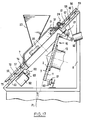
- the lock 88 When the lock 88 is retracted, the frame 16 and with it the motor 13 and the disc 2 can pivot down around the articulation 17 to the position shown in FIG. 17, called the purge position, in which the disc 2 has moved away from the cover 21, of the detector 31, of the lateral guide wall 7 and of the discharge blade 39.
- the disc 2 is then in a plane P 1 forming with the vertical direction an angle B less than the angle A of FIG. 3. This position is defined by pressing the mount 16 against a stop 91.
- the fall of foreign bodies likely to be on the disc 2 is favored, especially if these bodies were initially held captive by friction between the disc 2 and by example the cover 21, the discharge blade 39 secured to the cover 21 or the detector 31 fixed to the frame 8 of the device.
- the motor 13 it is possible to cause the motor 13 to rotate in alternating directions or in only one direction. This is possible because the pivoting of the mount 16 towards the purge position in no way affects the coupling between the motor 13 and the disc 2.
- An actuator 92 for example an electromagnet, is provided to bring the mount 16 back into the service position. This actuator 92 can also be used to shake the frame 16 and further promote the fall of foreign bodies.
- a so-called “conical” disc can be used, the cells of which are arranged in a truncated cone having an axis which may be vertical. There is thus at all points of the periphery a slope by which the parts tend to move radially towards the outside of the disc.
- the annular display itself has, advantageously a frustoconical shape.
- the hatches 49 and 50 can be replaced by pivoting flaps, or even by gates formed in the lateral guide wall.
Applications Claiming Priority (3)
| Application Number | Priority Date | Filing Date | Title |
|---|---|---|---|
| US07/849,564 US5232399A (en) | 1992-03-11 | 1992-03-11 | Devices for the separation of coins, token and the like |
| US849564 | 1992-03-11 | ||
| EP93918738A EP0587883B1 (de) | 1992-03-11 | 1993-03-10 | Vorrichtung zur trennung von münzen, automatenmünzen oder dergleichen und selbsttätige bezahlapparate |
Related Parent Applications (2)
| Application Number | Title | Priority Date | Filing Date |
|---|---|---|---|
| EP93918738.1 Division | 1993-03-10 | ||
| EP93918738A Division EP0587883B1 (de) | 1992-03-11 | 1993-03-10 | Vorrichtung zur trennung von münzen, automatenmünzen oder dergleichen und selbsttätige bezahlapparate |
Publications (2)
| Publication Number | Publication Date |
|---|---|
| EP0736848A2 true EP0736848A2 (de) | 1996-10-09 |
| EP0736848A3 EP0736848A3 (de) | 1998-12-23 |
Family
ID=25306007
Family Applications (4)
| Application Number | Title | Priority Date | Filing Date |
|---|---|---|---|
| EP96107719A Withdrawn EP0736848A3 (de) | 1992-03-11 | 1993-03-10 | Vorrichtungen zur Scheidung von Münzen, Wertmarken und dergleichen und automatische Zahlungsgeräte |
| EP96107720A Withdrawn EP0731428A3 (de) | 1992-03-11 | 1993-03-10 | Automatisches Zahlungsgerät |
| EP93918738A Expired - Lifetime EP0587883B1 (de) | 1992-03-11 | 1993-03-10 | Vorrichtung zur trennung von münzen, automatenmünzen oder dergleichen und selbsttätige bezahlapparate |
| EP96107718A Withdrawn EP0731427A3 (de) | 1992-03-11 | 1993-03-10 | Verfahren zur Erkennung von Objekten, wie zum Beispiel Münzen |
Family Applications After (3)
| Application Number | Title | Priority Date | Filing Date |
|---|---|---|---|
| EP96107720A Withdrawn EP0731428A3 (de) | 1992-03-11 | 1993-03-10 | Automatisches Zahlungsgerät |
| EP93918738A Expired - Lifetime EP0587883B1 (de) | 1992-03-11 | 1993-03-10 | Vorrichtung zur trennung von münzen, automatenmünzen oder dergleichen und selbsttätige bezahlapparate |
| EP96107718A Withdrawn EP0731427A3 (de) | 1992-03-11 | 1993-03-10 | Verfahren zur Erkennung von Objekten, wie zum Beispiel Münzen |
Country Status (5)
| Country | Link |
|---|---|
| US (3) | US5232399A (de) |
| EP (4) | EP0736848A3 (de) |
| AT (1) | ATE157473T1 (de) |
| DE (1) | DE69313389D1 (de) |
| WO (1) | WO1993018487A2 (de) |
Families Citing this family (51)
| Publication number | Priority date | Publication date | Assignee | Title |
|---|---|---|---|---|
| US5474496A (en) * | 1993-10-28 | 1995-12-12 | Perkitny; Jerzy | Coin bank |
| USRE36966E (en) * | 1992-10-30 | 2000-11-21 | Perkitny; Jerzy | Coin bank |
| FR2719143B1 (fr) * | 1994-04-22 | 1996-06-14 | Csee Peage | Contrôleur de pièces métalliques, notamment de pièces de monnaie. |
| WO1997025692A1 (en) * | 1996-01-11 | 1997-07-17 | Brandt, Inc. | Coin sorter with coin recognition |
| US5902178A (en) * | 1996-03-27 | 1999-05-11 | Mag-Nif Incorporated | Coin sorting apparatus |
| US5827117A (en) * | 1996-05-13 | 1998-10-27 | Mag-Nif Incorporated | Coin sorter and packager |
| US6520308B1 (en) * | 1996-06-28 | 2003-02-18 | Coinstar, Inc. | Coin discrimination apparatus and method |
| DE19633503C1 (de) * | 1996-08-08 | 1998-04-02 | Zimmermann Gmbh & Co Kg F | Verfahren zum Entladen des Tellerraumes von flachlaufenden Münzzähl- und Münzsortiermaschinen |
| DE19638285C2 (de) * | 1996-09-19 | 1998-07-02 | Farmont Technik | Spender für scheibenförmige Parktickets |
| US6168001B1 (en) * | 1997-06-27 | 2001-01-02 | Coinstar, Inc. | Positive drive coin discrimination apparatus and method |
| JPH11120401A (ja) * | 1997-10-16 | 1999-04-30 | Universal Hanbai Kk | コイン送出装置 |
| AU764752B2 (en) * | 1997-10-16 | 2003-08-28 | Universal Entertainment Corporation | Coin-sending device |
| JP4136179B2 (ja) * | 1999-04-22 | 2008-08-20 | アルゼ株式会社 | コイン送出装置 |
| FR2796628B1 (fr) | 1999-07-21 | 2001-09-21 | Snef Cote D Azur Sa | Tremie de traitement de pieces telles des pieces de monnaie |
| KR100600420B1 (ko) * | 1999-08-06 | 2006-07-13 | 아사히 세이코 가부시키가이샤 | 코인 호퍼 장치 |
| EP1330793B1 (de) * | 2000-09-05 | 2008-12-10 | Talaris Inc. | Verfahren und vorrichtung zum erkennen von münzwertigkeiten und anderen parametern |
| US7048623B2 (en) | 2001-02-09 | 2006-05-23 | Mag-Nif Incorporated | Coin separator and sorter assembly |
| US6592445B2 (en) * | 2001-03-21 | 2003-07-15 | Royal Sovereign, Inc. | Method and apparatus for sorting coins |
| US7152727B2 (en) * | 2001-09-21 | 2006-12-26 | Coinstar, Inc. | Method and apparatus for coin or object sensing using adaptive operating point control |
| US7822679B1 (en) * | 2001-10-29 | 2010-10-26 | Visa U.S.A. Inc. | Method and system for conducting a commercial transaction between a buyer and a seller |
| US20030154153A1 (en) * | 2002-01-31 | 2003-08-14 | Steidlmayer J. Peter | Composite commodity financial product |
| US6798353B2 (en) * | 2002-04-24 | 2004-09-28 | Itron Electricity Metering, Inc. | Method of using flash memory for storing metering data |
| DE10310894A1 (de) * | 2003-03-11 | 2004-09-30 | Scan Coin Industries Ab | Umlenkelement für Münzen |
| SE526494C2 (sv) * | 2003-07-02 | 2005-09-27 | Cashguard Ab | Matarenhet för separering av mynt |
| US7169035B2 (en) * | 2003-07-17 | 2007-01-30 | Aruze Corp. | Coin payout device utilizable in various devices |
| US8571978B2 (en) | 2004-06-17 | 2013-10-29 | Visa International Service Association | Method and system for providing assurance and financing services |
| GB2415692A (en) * | 2004-06-29 | 2006-01-04 | Money Controls Ltd | Coin dispensing apparatus for large coins |
| WO2006070606A1 (ja) * | 2004-12-28 | 2006-07-06 | Glory Kogyo Kabushiki Kaisha | 硬貨入出金機 |
| US7711639B2 (en) * | 2005-01-12 | 2010-05-04 | Visa International | Pre-funding system and method |
| CN101273387B (zh) * | 2005-09-30 | 2011-07-13 | 光荣株式会社 | 硬币分选系统 |
| US20090325475A1 (en) * | 2005-09-30 | 2009-12-31 | Yushi Hino | Coin Feeding Device |
| CA2694252C (en) * | 2006-08-08 | 2012-11-13 | Gregory F. String | Coin machine with self-cleaning intake hopper and related method |
| JP5066673B2 (ja) * | 2006-10-12 | 2012-11-07 | 旭精工株式会社 | コインホッパ |
| US7532111B2 (en) * | 2006-11-27 | 2009-05-12 | Larue Daniel V | System and method for graphically displaying a coin toss |
| US8031066B2 (en) * | 2006-11-27 | 2011-10-04 | Larue Daniel V | System and method for playing a game based on a coin toss |
| DE102007057427A1 (de) | 2007-11-29 | 2009-06-04 | Giesecke & Devrient Gmbh | Vorrichtung zum Vereinzeln von Münzen vorgegebener Typen und Verfahren zur Entfernung von Fremdkörpern bei einer Vereinzelung von Münzen vorgegebener Typen |
| JP5148703B2 (ja) * | 2008-07-23 | 2013-02-20 | グローリー株式会社 | 硬貨繰出装置および硬貨処理機 |
| EP2242029B1 (de) * | 2009-04-17 | 2012-12-19 | Crane Payment Solutions GmbH | Vorrichtung zum Vereinzeln und Prüfen von Münzen |
| JP5441256B2 (ja) * | 2009-12-28 | 2014-03-12 | グローリー株式会社 | 硬貨繰出装置および硬貨処理装置 |
| US8475242B2 (en) * | 2010-08-13 | 2013-07-02 | Gregory F. String | Coin sorting plate with recessed coin slots |
| DE102011005375A1 (de) * | 2011-03-10 | 2012-09-13 | Crane Payment Solutions Gmbh | Versorgungseinrichtung zur Befüllung eines Münzmoduls mit Münzen |
| US9036890B2 (en) | 2012-06-05 | 2015-05-19 | Outerwall Inc. | Optical coin discrimination systems and methods for use with consumer-operated kiosks and the like |
| JP5945773B2 (ja) * | 2012-12-18 | 2016-07-05 | 旭精工株式会社 | コインホッパ |
| US8967361B2 (en) | 2013-02-27 | 2015-03-03 | Outerwall Inc. | Coin counting and sorting machines |
| US9022841B2 (en) | 2013-05-08 | 2015-05-05 | Outerwall Inc. | Coin counting and/or sorting machines and associated systems and methods |
| GB2515516B (en) * | 2013-06-26 | 2017-10-11 | Innovative Tech Ltd | A coin transport mechanism |
| US9443367B2 (en) | 2014-01-17 | 2016-09-13 | Outerwall Inc. | Digital image coin discrimination for use with consumer-operated kiosks and the like |
| CN105788057A (zh) * | 2016-03-02 | 2016-07-20 | 同济大学 | 一种便携式钱币分拣装置 |
| US20180336752A1 (en) * | 2017-03-30 | 2018-11-22 | Tidel Engineering L.P. | Systems and methods for coin recycling |
| DK179422B1 (en) * | 2017-09-27 | 2018-06-18 | Ctcoin As | A coin separation mechanism and a coin processing apparatus comprising such a coin separation mechanism |
| GB202017594D0 (en) * | 2020-11-06 | 2020-12-23 | Crane Payment Innovations Ltd | Automated money item handling system and method of operation |
Citations (5)
| Publication number | Priority date | Publication date | Assignee | Title |
|---|---|---|---|---|
| GB2045502A (en) * | 1979-03-21 | 1980-10-29 | Mayfair Cigarette Co Ltd | Coin-separating apparatus |
| US4234003A (en) * | 1978-06-30 | 1980-11-18 | Ristvedt Victor G | Coin handling machine |
| US4561457A (en) * | 1984-03-01 | 1985-12-31 | Billcon Co., Ltd. | Coin sorter and counter |
| EP0345868A2 (de) * | 1988-06-04 | 1989-12-13 | Asahi Seiko Kabushiki Kaisha | Münzausgabevorrichtung |
| FR2633079A1 (fr) * | 1988-06-21 | 1989-12-22 | Lehong Son | Dispositif de controle automatique de pieces metalliques, notamment de pieces de monnaie |
Family Cites Families (24)
| Publication number | Priority date | Publication date | Assignee | Title |
|---|---|---|---|---|
| US788585A (en) * | 1902-09-22 | 1905-05-02 | Coin Counting Machine Company | Coin-counter. |
| US1210732A (en) * | 1913-11-06 | 1917-01-02 | American Coin Register Company | Coin separator and counter. |
| US2080389A (en) * | 1931-12-21 | 1937-05-11 | Rasmusen | Coin sorting machine |
| US2348936A (en) * | 1940-10-11 | 1944-05-16 | Brandt Automatic Cashier Co | Coin sorting and counting machine |
| US3396737A (en) * | 1966-03-17 | 1968-08-13 | Picollo Giacomo | Counting machine adjustable for coins of different diameters |
| US3696968A (en) * | 1970-12-10 | 1972-10-10 | Morton Norwich Products Inc | Article depositing machine improvement |
| US3783885A (en) * | 1972-06-27 | 1974-01-08 | P Griffiths | Disc dispensing apparatus |
| FR2288358A1 (fr) * | 1974-10-15 | 1976-05-14 | Vandeputte Fils & Cie | Machine pour trier les pieces de monnaie et similaires |
| FR2408183A1 (fr) * | 1977-11-03 | 1979-06-01 | Signaux Entr Electriques | Controleur de pieces metalliques, et notamment de pieces de monnaie |
| US4444212A (en) * | 1978-06-30 | 1984-04-24 | Ristvedt-Johnson, Inc. | Coin handling machine |
| GB2128795B (en) * | 1982-10-15 | 1986-03-19 | Mach & Systems Limited | Coin sorting apparatus |
| GB2137793B (en) * | 1983-02-08 | 1986-06-04 | Mars Inc | Coin handling apparatus |
| FR2542475B1 (fr) * | 1983-03-09 | 1985-08-09 | Signaux Entr Electriques | Controleur de pieces metalliques, en particulier de pieces de monnaie |
| US4793511A (en) * | 1984-03-26 | 1988-12-27 | Deere & Company | Seed meter having seed disk aperture cleaning wiper and brush arrangement |
| JPS61281385A (ja) * | 1985-06-07 | 1986-12-11 | 旭精工株式会社 | 硬貨投出装置 |
| CH667337A5 (de) * | 1985-06-21 | 1988-09-30 | Stoeckli Rudolf | Muenzsortiermaschine. |
| US4775353A (en) * | 1985-10-17 | 1988-10-04 | Childers Corporation | Spiral coin-queueing head for high-speed coin-sorting and counting apparatus |
| JPH0642291Y2 (ja) * | 1988-02-17 | 1994-11-02 | 三菱重工業株式会社 | 自動料金収受装置 |
| DE3811905A1 (de) * | 1988-04-09 | 1989-10-19 | Ewald Rollnik | Anordnung zum erkennen und sichern von gegenstaenden sowie deren verwendung |
| US4898564A (en) * | 1988-08-16 | 1990-02-06 | Brink's Incorporated | Apparatus for coin sorting and counting |
| DE3907354A1 (de) * | 1989-03-08 | 1990-09-13 | Reis Standardwerk | Sortiereinrichtung fuer muenzen oder dergleichen scheibenfoermige gegenstaende |
| US4987990A (en) * | 1989-07-25 | 1991-01-29 | Mag-Nif, Inc. | Coin Bank |
| AT401436B (de) * | 1989-10-16 | 1996-09-25 | Pohanka Christian Ing | Vorrichtung zum sortieren von chips an spieltischen |
| US5122093A (en) * | 1990-12-28 | 1992-06-16 | Mag-Nif, Inc. | Coin bank |
-
1992
- 1992-03-11 US US07/849,564 patent/US5232399A/en not_active Expired - Lifetime
-
1993
- 1993-01-21 US US08/006,994 patent/US5238446A/en not_active Expired - Lifetime
- 1993-01-21 US US08/006,993 patent/US5285883A/en not_active Expired - Lifetime
- 1993-03-10 AT AT93918738T patent/ATE157473T1/de active
- 1993-03-10 DE DE69313389T patent/DE69313389D1/de not_active Expired - Lifetime
- 1993-03-10 EP EP96107719A patent/EP0736848A3/de not_active Withdrawn
- 1993-03-10 EP EP96107720A patent/EP0731428A3/de not_active Withdrawn
- 1993-03-10 EP EP93918738A patent/EP0587883B1/de not_active Expired - Lifetime
- 1993-03-10 WO PCT/FR1993/000235 patent/WO1993018487A2/fr active IP Right Grant
- 1993-03-10 EP EP96107718A patent/EP0731427A3/de not_active Withdrawn
Patent Citations (5)
| Publication number | Priority date | Publication date | Assignee | Title |
|---|---|---|---|---|
| US4234003A (en) * | 1978-06-30 | 1980-11-18 | Ristvedt Victor G | Coin handling machine |
| GB2045502A (en) * | 1979-03-21 | 1980-10-29 | Mayfair Cigarette Co Ltd | Coin-separating apparatus |
| US4561457A (en) * | 1984-03-01 | 1985-12-31 | Billcon Co., Ltd. | Coin sorter and counter |
| EP0345868A2 (de) * | 1988-06-04 | 1989-12-13 | Asahi Seiko Kabushiki Kaisha | Münzausgabevorrichtung |
| FR2633079A1 (fr) * | 1988-06-21 | 1989-12-22 | Lehong Son | Dispositif de controle automatique de pieces metalliques, notamment de pieces de monnaie |
Also Published As
| Publication number | Publication date |
|---|---|
| EP0731428A3 (de) | 1998-09-30 |
| WO1993018487A3 (fr) | 1994-02-17 |
| EP0731428A2 (de) | 1996-09-11 |
| US5232399A (en) | 1993-08-03 |
| EP0736848A3 (de) | 1998-12-23 |
| EP0587883B1 (de) | 1997-08-27 |
| ATE157473T1 (de) | 1997-09-15 |
| EP0731427A2 (de) | 1996-09-11 |
| EP0587883A1 (de) | 1994-03-23 |
| US5285883A (en) | 1994-02-15 |
| WO1993018487A2 (fr) | 1993-09-16 |
| DE69313389D1 (de) | 1997-10-02 |
| US5238446A (en) | 1993-08-24 |
| EP0731427A3 (de) | 1998-09-30 |
Similar Documents
| Publication | Publication Date | Title |
|---|---|---|
| EP0587883B1 (de) | Vorrichtung zur trennung von münzen, automatenmünzen oder dergleichen und selbsttätige bezahlapparate | |
| CA1318610C (fr) | Dispositif de stockage et de distribution d'objets | |
| BE1005489A5 (fr) | Systeme a tube pneumatique pour transfert d'objets. | |
| FR2849519A1 (fr) | Porte automatisee pour permettre ou interdire l'acces a un espace ou un vehicule de transport, en particulier a une salle d'embarquement ou a un avion | |
| JPH10124727A (ja) | 水平に走行するコイン計数・コイン分類機械のトレイ空間を空にするための方法 | |
| WO2002045036A1 (fr) | Appareil securise a pieces de monnaie | |
| EP0627712B1 (de) | Vorrichtung zum Sortieren und Speichern von zur Bezahlung in eine Ausgabevorrichtung eingeführten Gegenständen | |
| EP1268091A2 (de) | Vorrichtung zum automatischen selektiven sortieren | |
| FR2804529A1 (fr) | Dispositif de dechargement d'articles | |
| EP0678835B1 (de) | Münzprüfer | |
| FR2614609A1 (fr) | Tour magasin de stockage d'objets | |
| FR2667421A1 (fr) | Distributeur de gobelets empiles en position inversee. | |
| BE1008100A5 (fr) | Procede et dispositif de recolte selective d'objets en verre et de stockage temporaire de leur matiere. | |
| FR2634636A1 (fr) | Dispositif de distribution automatique de bouteilles de gaz liquefie a section circulaire | |
| EP1107925B1 (de) | Automatische vorrichtung zur abgabe von gegenständen auf gleitschienen | |
| EP0281716A1 (de) | Maschine zur Pfandrückgabe für von Supermärkten zurückgenommene leere Flaschen | |
| FR2587012A1 (fr) | Distributeur automatique de billets de banque | |
| EP1408461B1 (de) | Fördersystem für Becher in einem Getränkeautomat | |
| EP0322269A1 (de) | Automatische Ausgabevorrichtung für Beutel | |
| WO2004051368A1 (fr) | Dispositif pour le stockage et la distribution d'objets | |
| FR2587134A1 (fr) | Compartiment caisse en particulier pour appareils a monnaie tels que les publiphones | |
| BE879828R (fr) | Appareil pour mettre automatiquement en boite des objets cylindriques et boite, notamment pour un tel appareil | |
| FR2611670A2 (fr) | Dispositif de stockage et de distribution d'objets | |
| EP0668574A1 (de) | Fahrkartenausgabevorrichtung für eine Fahrkartenherstellungs- und Ausgabemaschine | |
| FR2722529A1 (fr) | Paroi de securite pour la communication entre deuxutilisateurs et installation comprenant une telle paroi |
Legal Events
| Date | Code | Title | Description |
|---|---|---|---|
| PUAI | Public reference made under article 153(3) epc to a published international application that has entered the european phase |
Free format text: ORIGINAL CODE: 0009012 |
|
| AC | Divisional application: reference to earlier application |
Ref document number: 587883 Country of ref document: EP |
|
| AK | Designated contracting states |
Kind code of ref document: A2 Designated state(s): AT DE ES FR GB |
|
| PUAL | Search report despatched |
Free format text: ORIGINAL CODE: 0009013 |
|
| AK | Designated contracting states |
Kind code of ref document: A3 Designated state(s): AT DE ES FR GB |
|
| 17P | Request for examination filed |
Effective date: 19990315 |
|
| 17Q | First examination report despatched |
Effective date: 20010420 |
|
| GRAG | Despatch of communication of intention to grant |
Free format text: ORIGINAL CODE: EPIDOS AGRA |
|
| GRAG | Despatch of communication of intention to grant |
Free format text: ORIGINAL CODE: EPIDOS AGRA |
|
| GRAH | Despatch of communication of intention to grant a patent |
Free format text: ORIGINAL CODE: EPIDOS IGRA |
|
| STAA | Information on the status of an ep patent application or granted ep patent |
Free format text: STATUS: THE APPLICATION IS DEEMED TO BE WITHDRAWN |
|
| 18D | Application deemed to be withdrawn |
Effective date: 20020430 |