EP0734945A1 - Fahrrad mit elektromotorischem Hilfsantrieb - Google Patents
Fahrrad mit elektromotorischem Hilfsantrieb Download PDFInfo
- Publication number
- EP0734945A1 EP0734945A1 EP96301372A EP96301372A EP0734945A1 EP 0734945 A1 EP0734945 A1 EP 0734945A1 EP 96301372 A EP96301372 A EP 96301372A EP 96301372 A EP96301372 A EP 96301372A EP 0734945 A1 EP0734945 A1 EP 0734945A1
- Authority
- EP
- European Patent Office
- Prior art keywords
- motor
- electrically powered
- driving force
- powered bicycle
- acceleration
- Prior art date
- Legal status (The legal status is an assumption and is not a legal conclusion. Google has not performed a legal analysis and makes no representation as to the accuracy of the status listed.)
- Granted
Links
- 230000001133 acceleration Effects 0.000 claims abstract description 39
- 230000009347 mechanical transmission Effects 0.000 claims description 4
- 238000013016 damping Methods 0.000 claims description 2
- 238000010276 construction Methods 0.000 description 3
- 230000002411 adverse Effects 0.000 description 2
- 230000005540 biological transmission Effects 0.000 description 2
- OJIJEKBXJYRIBZ-UHFFFAOYSA-N cadmium nickel Chemical compound [Ni].[Cd] OJIJEKBXJYRIBZ-UHFFFAOYSA-N 0.000 description 2
- 229910052748 manganese Inorganic materials 0.000 description 2
- 239000011572 manganese Substances 0.000 description 2
- PWHULOQIROXLJO-UHFFFAOYSA-N Manganese Chemical compound [Mn] PWHULOQIROXLJO-UHFFFAOYSA-N 0.000 description 1
- QMRWLXUKPFCDML-UHFFFAOYSA-N [O].[Ag].[Cd] Chemical compound [O].[Ag].[Cd] QMRWLXUKPFCDML-UHFFFAOYSA-N 0.000 description 1
- 239000003513 alkali Substances 0.000 description 1
- 239000003638 chemical reducing agent Substances 0.000 description 1
- QSHDDOUJBYECFT-UHFFFAOYSA-N mercury Chemical compound [Hg] QSHDDOUJBYECFT-UHFFFAOYSA-N 0.000 description 1
- 229910052753 mercury Inorganic materials 0.000 description 1
- 238000012986 modification Methods 0.000 description 1
- 230000004048 modification Effects 0.000 description 1
- HTQOEHYNHFXMJJ-UHFFFAOYSA-N oxosilver zinc Chemical compound [Zn].[Ag]=O HTQOEHYNHFXMJJ-UHFFFAOYSA-N 0.000 description 1
Images


Classifications
-
- B—PERFORMING OPERATIONS; TRANSPORTING
- B62—LAND VEHICLES FOR TRAVELLING OTHERWISE THAN ON RAILS
- B62M—RIDER PROPULSION OF WHEELED VEHICLES OR SLEDGES; POWERED PROPULSION OF SLEDGES OR SINGLE-TRACK CYCLES; TRANSMISSIONS SPECIALLY ADAPTED FOR SUCH VEHICLES
- B62M6/00—Rider propulsion of wheeled vehicles with additional source of power, e.g. combustion engine or electric motor
- B62M6/40—Rider propelled cycles with auxiliary electric motor
- B62M6/45—Control or actuating devices therefor
-
- B—PERFORMING OPERATIONS; TRANSPORTING
- B60—VEHICLES IN GENERAL
- B60L—PROPULSION OF ELECTRICALLY-PROPELLED VEHICLES; SUPPLYING ELECTRIC POWER FOR AUXILIARY EQUIPMENT OF ELECTRICALLY-PROPELLED VEHICLES; ELECTRODYNAMIC BRAKE SYSTEMS FOR VEHICLES IN GENERAL; MAGNETIC SUSPENSION OR LEVITATION FOR VEHICLES; MONITORING OPERATING VARIABLES OF ELECTRICALLY-PROPELLED VEHICLES; ELECTRIC SAFETY DEVICES FOR ELECTRICALLY-PROPELLED VEHICLES
- B60L15/00—Methods, circuits, or devices for controlling the traction-motor speed of electrically-propelled vehicles
- B60L15/20—Methods, circuits, or devices for controlling the traction-motor speed of electrically-propelled vehicles for control of the vehicle or its driving motor to achieve a desired performance, e.g. speed, torque, programmed variation of speed
-
- B—PERFORMING OPERATIONS; TRANSPORTING
- B62—LAND VEHICLES FOR TRAVELLING OTHERWISE THAN ON RAILS
- B62M—RIDER PROPULSION OF WHEELED VEHICLES OR SLEDGES; POWERED PROPULSION OF SLEDGES OR SINGLE-TRACK CYCLES; TRANSMISSIONS SPECIALLY ADAPTED FOR SUCH VEHICLES
- B62M6/00—Rider propulsion of wheeled vehicles with additional source of power, e.g. combustion engine or electric motor
- B62M6/40—Rider propelled cycles with auxiliary electric motor
- B62M6/60—Rider propelled cycles with auxiliary electric motor power-driven at axle parts
Definitions
- the present invention relates to electrically powered bicycles and, more particularly, to an electrically powered bicycle with a motor used as an auxiliary driving force for assisting pedaling.
- Conventional electrically powered bicycles include a bicycle comprising a pedaling sensor for detecting a main driving force generated by pedaling and a battery current sensor for detecting motor torque based on a battery current supplied from a battery to a motor, in which an auxiliary driving force is generated by a motor and controlled based on an output from the sensor (see, for example, Japanese Unexamined Patent Publication No. HEI 4(1992)-100790), and a bicycle with a motor for outputting an auxiliary driving force only when a main driving force exceeds a predetermined value (see, for example, Japanese Unexamined Patent Publication No. HEI 5(1993)-246378).
- the present invention has been made in view of the above circumstances, and provides an electrically powered bicycle with a motor for outputting a required auxiliary driving force in accordance with running acceleration of the electrically powered bicycle to properly assist running with a main driving force.
- the present invention provides an electrically powered bicycle that is driven by a main driving force generated by pedaling and an auxiliary driving force, comprising a motor for generating the auxiliary driving force, a battery for supplying electric power to the motor, an acceleration sensor for detecting running acceleration of the electrically powered bicycle, and control means for controlling the electric power to be supplied to the motor so that the motor outputs the auxiliary driving force in accordance with the running acceleration thus detected.
- the motor outputs the auxiliary driving force in accordance with the acceleration of the bicycle, thereby reducing the main driving force required at the time of the acceleration to facilitate driving.
- the main driving force referred to in the present invention is, as seen in conventional bicycles, a force transmitted to a driving wheel by a rider's pushing on pedals, and a mechanical transmission system for transmitting the main driving force from the pedals to the driving wheel can be any means known in conventional bicycles.
- the auxiliary driving force is a driving force auxiliarily provided from the motor to the driving wheel.
- the bicycle further comprises a pedaling sensor for detecting the main driving force and a stopping means for stopping the output of the auxiliary driving force of the motor when the pedaling sensor does not detect the main driving force.
- a pedaling sensor for detecting the main driving force
- a stopping means for stopping the output of the auxiliary driving force of the motor when the pedaling sensor does not detect the main driving force.
- the pedaling sensor may comprise a combination of an element for generating a mechanical strain or deformation and a sensor for converting the strain or deformation into an electric signal.
- the element is disposed in the mechanical transmission system for the main driving force to generate a mechanical strain or deformation caused by the main driving force.
- the sensor may be, for example, a strain gauge, a potentiometer or a differential transformer.
- auxiliary driving force from the motor to the driving wheel of the bicycle there are employed means for transmitting the output from the motor to the rotary axle of the driving wheel via a gear of several stages, a belt or a chain, means for transmitting the output from the motor to a tire or a rim of the driving wheel after the rotation speed of an output shaft of the motor is reduced by a gear, and the like.
- the motor and the driving wheel are connected together via a one way clutch to prevent supply of damping force from the motor to the driving wheel when the driving wheel has a higher rotation speed than is given by the motor.
- the motor may be, for example, a brushless motor or a brush motor, among which a DC brush motor is preferably used because of the facility in control.
- the battery may be, for example, a dry battery such as a manganese battery, a mercury battery or an alkali-manganese battery or a rechargeable battery such as a lead storage battery, an alkali storage battery, a silver oxide-zinc storage battery, a silver oxide-cadmium battery or a nickel-cadmium battery.
- the battery may be detachably housed in a casing provided above the driving wheel or detachably housed inside a tubular pipe that constitutes the body frame of the bicycle.
- the running acceleration sensor can be a piezoelectric acceleration sensor (manufactured by, for example, YAMCO CO., LTD. in Japan, 201S type), a servo acceleration meter (manufactured by TOKIMEC INC. in Japan, TA25 type) and a linear acceleration meter (manufactured by TOKYO AIRCRAFT INSTRUMENT CO., LTD. in Japan, 4311 type).
- the running acceleration sensor may be a combination of a speed sensor with a circuit for differentiating an output of the speed sensor to give acceleration.
- the control means may be constituted of a switching element (e.g., switching transistor and thyristor) for supplying electric power from the battery to the motor and of a duty control circuit for controlling a duty factor of the switching element in accordance with the running acceleration.
- a switching element e.g., switching transistor and thyristor
- the duty control circuit turns the switching element on and off by outputting a pulse signal with a predetermined frequency of, for example, on the order of 100 to 1000 Hz or 1 to 10 ms to vary its duty factor for placing the motor under PWM control.
- a pulse signal with a predetermined frequency for example, on the order of 100 to 1000 Hz or 1 to 10 ms to vary its duty factor for placing the motor under PWM control.
- the duty factor of the switching element is a ratio of the time for "on" relative to a predetermined frequency when the switching element is turned on and off at the frequency.
- the speed sensor is a sensor for detecting the running speed of the electrically powered bicycle.
- Examples of the speed sensor are a rotary encoder and a tachogenerator for measuring the rotation speed of the driving wheel.
- the controlling means controls the electric power to be supplied to the motor such that the motor outputs the auxiliary driving force in accordance with the detected running acceleration.
- the auxiliary driving force is outputted at the time of acceleration when an increased driving force is required, thereby facilitating acceleration of the electrically powered bicycle with less pedaling effort.
- Fig. 1 is a side view of an electrically powered bicycle in accordance with one embodiment of the present invention.
- Fig. 2 is an explanatory view for the construction of the driving system of the electrically powered bicycle.
- a body 1 of the electrically powered bicycle has a driving wheel 2 that is driven by pedaling means 9 and motor means 12, and a front wheel 3 for determining a running direction.
- the body 1 has a frame constituted of a seat tube 4, a top tube 5 and a down tube 6, and on the upper end of the seat tube 4 is mounted a saddle 7. Upper from an intersection of the top tube 5 and the down tube 6 is provided a handle 8 for determining a direction of the front wheel 3.
- the pedaling means 9 for driving the driving wheel 2 is provided with, like conventional bicycles, pedals 10 so that a rider pushes and rotates the pedals 10 by his feet to transmit driving force (referred to also as pedaling force) to a chain 11 and then to the driving wheel 2 via a sprocket lla and a one way clutch 11b, thereby driving the driving wheel 2.
- driving force referred to also as pedaling force
- the one way clutch 11b is such that, when the driving wheel 2 has a higher rotation speed than the pedaling force intends to give to the driving wheel 2, the one way clutch 11b prevents adverse transmission of the driving force from the driving wheel 2 to the chain 11.
- the motor means 12 that drives the driving wheel 2 in association with the pedaling means 9 is powered by a rechargeable battery 13 disposed over the driving wheel 2, and supplies electric power from the battery 13 to a motor 14 provided on a hub of the driving wheel 2.
- an output from the motor 14 is reduced by a speed reducer mechanism 14a including a gear and a belt, and is transmitted to the driving wheel 2 via a one way clutch 14b and a speed sensor 14c.
- the one way clutch 14b is such that, when the driving wheel 2 has a higher rotation speed than the motor 14 intends to give to the driving wheel 2, the one way clutch 14b prevents adverse transmission of the driving force from the driving wheel 2 to the motor 14.
- the speed sensor 14c disposed on the rotary axle of the driving wheel 2, is a rotary encoder that outputs pulses with a frequency proportional to the rotation speed of the driving wheel 2.
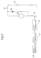
- FIG. 3 a control circuit of the electrically powered bicycle will be detailed.
- a voltage from the battery 13 is applied to the motor 14 via a switching element 21 and a power supply switch 19.
- a flywheel diode 20 In parallel to the motor 14 is arranged and connected thereto a flywheel diode 20, as shown in Fig. 3.
- Reference numeral 17 denotes a microcomputer including a CPU, a ROM and a RAM, which carries out a signal processing on receipt of an output signal from the speed sensor 14c and sends a duty control signal to a pulse generator 18.
- the pulse generator 18, on receipt of the duty control signal from the microcomputer 17, controls a duty factor of the switching element 21.
- a DC brush motor of the permanent magnetic type (maximum output: 300W) is employed as the motor 14 and a nickel-cadmium battery of 24V and 5Ah as the battery 13.
- the microcomputer 17 turns the switching element 21 on and off with a frequency of 244Hz to place the motor 14 under PWM control.
- Such a construction of the electrically powered bicycle allows the pedaling force generated by the rider's pushing on the pedals 10 to be transmitted to the driving wheel 2 via the chain 11.
- the microcomputer 17 senses a speed v from the output signal of the speed sensor 14c (step S1), differentiates the speed v to give acceleration ⁇ (steps S2 and S3), determines a duty factory ⁇ based on a function or table which is preestablished such that, with the increase of the acceleration ⁇ , the duty factor becomes higher (step S4), and drives the switching element 21 with the duty factor ⁇ thus obtained (step S5).
- Fig. 5 is a time chart illustrating the change in accordance with time of the speed v, the acceleration ⁇ and the duty factor ⁇ for the above control.
- the speed v starts to increase to give acceleration ⁇ 1.
- duty factor ⁇ 1 which is determined based on the acceleration ⁇ 1, electric power is supplied from the battery 13 to the motor 14, thus giving auxiliary power to the bicycle (time T1).
- auxiliary driving force is given to the electrically powered bicycle with duty factory ⁇ 2 determined based on the acceleration ⁇ 2. It should be noted that at time T3 for speed reduction with ⁇ ⁇ 0, the auxiliary driving force is not outputted.
- the auxiliary driving force is provided in accordance with acceleration, thereby reducing main driving force required at the time of acceleration of the electrically powered bicycle for facilitated driving.
- the motor outputs the auxiliary driving force in accordance with acceleration of the electrically powered bicycle, thereby reducing the pedaling force required at the time of acceleration of the electrically powered bicycle for facilitated driving.
Landscapes
- Engineering & Computer Science (AREA)
- Chemical & Material Sciences (AREA)
- Combustion & Propulsion (AREA)
- Transportation (AREA)
- Mechanical Engineering (AREA)
- Power Engineering (AREA)
- Electric Propulsion And Braking For Vehicles (AREA)
- Automatic Cycles, And Cycles In General (AREA)
Applications Claiming Priority (3)
| Application Number | Priority Date | Filing Date | Title |
|---|---|---|---|
| JP7068083A JPH08258782A (ja) | 1995-03-27 | 1995-03-27 | 電動自転車 |
| JP68083/95 | 1995-03-27 | ||
| JP6808395 | 1995-03-27 |
Publications (2)
| Publication Number | Publication Date |
|---|---|
| EP0734945A1 true EP0734945A1 (de) | 1996-10-02 |
| EP0734945B1 EP0734945B1 (de) | 1999-07-28 |
Family
ID=13363509
Family Applications (1)
| Application Number | Title | Priority Date | Filing Date |
|---|---|---|---|
| EP96301372A Expired - Lifetime EP0734945B1 (de) | 1995-03-27 | 1996-02-28 | Fahrrad mit elektromotorischem Hilfsantrieb |
Country Status (7)
| Country | Link |
|---|---|
| US (1) | US5819867A (de) |
| EP (1) | EP0734945B1 (de) |
| JP (1) | JPH08258782A (de) |
| KR (1) | KR960034000A (de) |
| CN (1) | CN1078153C (de) |
| AT (1) | ATE182537T1 (de) |
| DE (1) | DE69603397T2 (de) |
Cited By (8)
| Publication number | Priority date | Publication date | Assignee | Title |
|---|---|---|---|---|
| WO1998003392A1 (de) * | 1996-07-18 | 1998-01-29 | Luna Gmbh Leichte Umweltfreundliche Nahverkehrsalternativen | Verfahren und vorrichtung zur steuerung von elektromotoren |
| WO1999030959A1 (de) * | 1997-12-12 | 1999-06-24 | Rolf Strothmann | Steuerung für auf muskel- und motorkraft gestützte antriebe |
| EP0926059A3 (de) * | 1997-12-24 | 2001-03-21 | Matsushita Electric Industrial Co., Ltd. | Fahrzeug mit Hilfsmotor und Verfahren zu dessen Regelung |
| WO2002024520A1 (en) * | 2000-09-21 | 2002-03-28 | Dube Jean Yves | Method and apparatus for proportionally assisted propulsion |
| EP1129934A3 (de) * | 2000-03-01 | 2004-05-19 | Honda Giken Kogyo Kabushiki Kaisha | Antriebseinheit für Fahrräder |
| CN103339026A (zh) * | 2011-01-31 | 2013-10-02 | 三洋电机株式会社 | 电动自行车 |
| CN105966537A (zh) * | 2015-11-26 | 2016-09-28 | 衡阳市利美电瓶车制造有限责任公司 | 一种驱动装置 |
| CN106585849A (zh) * | 2016-11-21 | 2017-04-26 | 天津逍悦达科技有限公司 | 一种通过三轴加速度传感器实现自行车智能助力方法 |
Families Citing this family (22)
| Publication number | Priority date | Publication date | Assignee | Title |
|---|---|---|---|---|
| EP1236640B1 (de) * | 2001-02-28 | 2007-11-07 | Honda Giken Kogyo Kabushiki Kaisha | Steuerungseinrichtung für Fahrrad mit Hilfsmotor |
| US6619416B2 (en) * | 2001-03-23 | 2003-09-16 | Mey-Chu Lan | Brake lever-controlled power scooter control system |
| GB2446229B (en) * | 2007-02-05 | 2010-12-29 | Akhter Group Plc | Battery system for electrical vehicle |
| AU2009100700B4 (en) * | 2009-07-02 | 2009-11-12 | Nanocycle Pty Ltd | Improvements to power assisted vehicles |
| JP5564389B2 (ja) * | 2010-09-30 | 2014-07-30 | 本田技研工業株式会社 | 電動補助自転車の制御装置 |
| DE102011005520A1 (de) | 2011-03-14 | 2012-09-20 | Grace Gmbh & Co.Kg | Zweiradrahmen, insbesondere für Elektrofahrräder, mit eine Aufnahme aufspannendes Profilelement |
| DE102012201881A1 (de) * | 2012-02-09 | 2013-01-17 | Robert Bosch Gmbh | Steuerungsanordnung für ein Elektrofahrrad |
| TW201345780A (zh) * | 2012-05-08 | 2013-11-16 | Univ Nat Chiao Tung | 具自行車架外形之嵌入式工業控制器 |
| KR20140038043A (ko) * | 2012-09-19 | 2014-03-28 | 주식회사 만도 | 전기 자전거 구동 장치 |
| TWI558613B (zh) | 2013-05-13 | 2016-11-21 | 達方電子股份有限公司 | 電動助力車之自動調整方法 |
| JP2015044526A (ja) * | 2013-08-29 | 2015-03-12 | 太陽誘電株式会社 | モータ駆動制御装置及び電動アシスト車 |
| WO2015125430A1 (ja) * | 2014-02-18 | 2015-08-27 | パナソニックIpマネジメント株式会社 | 蓄電装置の制御方法、蓄電装置及びプログラム |
| JP5986150B2 (ja) * | 2014-07-17 | 2016-09-06 | 株式会社シマノ | 自転車用制御装置、自転車用制御装置を備える電動アシスト自転車、及び電動アシスト自転車のモータ制御方法 |
| DE102015010817A1 (de) | 2015-08-23 | 2017-02-23 | Karlheinz Nicolai | Halterung mit klappbarer Schutzabdeckung für Energiespeicher mit schneller werkzeugloser Wechselmöglichkeit von einem oder mehreren Energiespeichern für den Einsatz an Geräten und Fahrzeugen |
| US9925999B2 (en) | 2015-09-29 | 2018-03-27 | Radio Flyer Inc. | Power assist wagon |
| CN105644695A (zh) * | 2016-03-23 | 2016-06-08 | 黄学禹 | 一种电动自行车及控制方法 |
| US10583852B2 (en) | 2016-11-02 | 2020-03-10 | Radio Flyer Inc. | Foldable wagon |
| USD866676S1 (en) | 2017-11-02 | 2019-11-12 | Radio Flyer Inc. | Foldable wagon |
| CN109895929B (zh) * | 2017-12-07 | 2022-03-29 | 弗莱克斯有限公司 | 用于电动助力自行车的电子离合器 |
| WO2019188042A1 (ja) * | 2018-03-29 | 2019-10-03 | パナソニックIpマネジメント株式会社 | 自転車電動化装置、及び、車輪 |
| CN109606529A (zh) * | 2019-01-22 | 2019-04-12 | 任海军 | 一种电动车自动档动力控制系统 |
| DE102024206388A1 (de) * | 2024-07-08 | 2026-01-08 | Zf Friedrichshafen Ag | Verfahren zur Ansteuerung eines Elektromotors eines Antriebssystems |
Citations (4)
| Publication number | Priority date | Publication date | Assignee | Title |
|---|---|---|---|---|
| JPH04100790A (ja) * | 1990-08-16 | 1992-04-02 | Yamaha Motor Co Ltd | 電動モータ付き人力駆動装置 |
| JPH0550977A (ja) * | 1991-08-19 | 1993-03-02 | Yasushi Sakano | 自転車 |
| JPH05246378A (ja) * | 1992-03-09 | 1993-09-24 | Yamaha Motor Co Ltd | 電動モータ付き自転車 |
| EP0635423A1 (de) * | 1993-07-23 | 1995-01-25 | Yamaha Hatsudoki Kabushiki Kaisha | Muskelgetriebenes Fahrzeug |
Family Cites Families (8)
| Publication number | Priority date | Publication date | Assignee | Title |
|---|---|---|---|---|
| US3921745A (en) * | 1973-07-23 | 1975-11-25 | Mcculloch Corp | Electric bicycle |
| US3939932A (en) * | 1974-07-22 | 1976-02-24 | Rosen Henri E | Exercise apparatus |
| DE2929505A1 (de) * | 1978-07-20 | 1980-01-31 | Yamaha Motor Co Ltd | Vorrichtung zur regelung der geschwindigkeit eines radfahrzeuges |
| JPS55977A (en) * | 1979-02-07 | 1980-01-07 | Tokyo Electric Co Ltd | Paper cutting device in print paper issue section |
| GB8806042D0 (en) * | 1988-03-14 | 1988-04-13 | Lean G D | Proportional control system for engine assisted bicycle |
| JP2634121B2 (ja) * | 1992-03-06 | 1997-07-23 | ヤマハ発動機株式会社 | 電動モータ付き自転車およびそのモータ制御方法 |
| CN1050576C (zh) * | 1993-09-14 | 2000-03-22 | 株式会社利肯 | 电动自行车 |
| JPH07212904A (ja) * | 1994-01-18 | 1995-08-11 | Yamaha Motor Co Ltd | 電気自動車用電源スイッチ |
-
1995
- 1995-03-27 JP JP7068083A patent/JPH08258782A/ja active Pending
-
1996
- 1996-02-23 KR KR1019960004249A patent/KR960034000A/ko not_active Ceased
- 1996-02-27 US US08/607,357 patent/US5819867A/en not_active Expired - Fee Related
- 1996-02-28 EP EP96301372A patent/EP0734945B1/de not_active Expired - Lifetime
- 1996-02-28 AT AT96301372T patent/ATE182537T1/de not_active IP Right Cessation
- 1996-02-28 DE DE69603397T patent/DE69603397T2/de not_active Expired - Fee Related
- 1996-03-26 CN CN96103741A patent/CN1078153C/zh not_active Expired - Fee Related
Patent Citations (4)
| Publication number | Priority date | Publication date | Assignee | Title |
|---|---|---|---|---|
| JPH04100790A (ja) * | 1990-08-16 | 1992-04-02 | Yamaha Motor Co Ltd | 電動モータ付き人力駆動装置 |
| JPH0550977A (ja) * | 1991-08-19 | 1993-03-02 | Yasushi Sakano | 自転車 |
| JPH05246378A (ja) * | 1992-03-09 | 1993-09-24 | Yamaha Motor Co Ltd | 電動モータ付き自転車 |
| EP0635423A1 (de) * | 1993-07-23 | 1995-01-25 | Yamaha Hatsudoki Kabushiki Kaisha | Muskelgetriebenes Fahrzeug |
Non-Patent Citations (3)
| Title |
|---|
| PATENT ABSTRACTS OF JAPAN vol. 16, no. 339 (M - 1284) 22 July 1992 (1992-07-22) * |
| PATENT ABSTRACTS OF JAPAN vol. 17, no. 358 (M - 1440) 7 July 1993 (1993-07-07) * |
| PATENT ABSTRACTS OF JAPAN vol. 17, no. 709 (M - 1535) 24 December 1993 (1993-12-24) * |
Cited By (11)
| Publication number | Priority date | Publication date | Assignee | Title |
|---|---|---|---|---|
| WO1998003392A1 (de) * | 1996-07-18 | 1998-01-29 | Luna Gmbh Leichte Umweltfreundliche Nahverkehrsalternativen | Verfahren und vorrichtung zur steuerung von elektromotoren |
| WO1999030959A1 (de) * | 1997-12-12 | 1999-06-24 | Rolf Strothmann | Steuerung für auf muskel- und motorkraft gestützte antriebe |
| US6545437B1 (en) | 1997-12-12 | 2003-04-08 | Rolf Strothmann | Control for a muscle or motor-powered drive |
| EP0926059A3 (de) * | 1997-12-24 | 2001-03-21 | Matsushita Electric Industrial Co., Ltd. | Fahrzeug mit Hilfsmotor und Verfahren zu dessen Regelung |
| EP1129934A3 (de) * | 2000-03-01 | 2004-05-19 | Honda Giken Kogyo Kabushiki Kaisha | Antriebseinheit für Fahrräder |
| WO2002024520A1 (en) * | 2000-09-21 | 2002-03-28 | Dube Jean Yves | Method and apparatus for proportionally assisted propulsion |
| US6866111B2 (en) | 2000-09-21 | 2005-03-15 | Jean-Yves Dubé | Method and apparatus for proportionally assisted propulsion |
| CN103339026A (zh) * | 2011-01-31 | 2013-10-02 | 三洋电机株式会社 | 电动自行车 |
| EP2671788A4 (de) * | 2011-01-31 | 2014-10-29 | Sanyo Electric Co | Elektrisches fahrrad |
| CN105966537A (zh) * | 2015-11-26 | 2016-09-28 | 衡阳市利美电瓶车制造有限责任公司 | 一种驱动装置 |
| CN106585849A (zh) * | 2016-11-21 | 2017-04-26 | 天津逍悦达科技有限公司 | 一种通过三轴加速度传感器实现自行车智能助力方法 |
Also Published As
| Publication number | Publication date |
|---|---|
| EP0734945B1 (de) | 1999-07-28 |
| KR960034000A (ko) | 1996-10-22 |
| ATE182537T1 (de) | 1999-08-15 |
| US5819867A (en) | 1998-10-13 |
| CN1078153C (zh) | 2002-01-23 |
| DE69603397D1 (de) | 1999-09-02 |
| CN1137996A (zh) | 1996-12-18 |
| DE69603397T2 (de) | 1999-11-18 |
| JPH08258782A (ja) | 1996-10-08 |
Similar Documents
| Publication | Publication Date | Title |
|---|---|---|
| US5819867A (en) | Electrically powered bicycle | |
| US6015021A (en) | Electrically assisted vehicle | |
| CN100453400C (zh) | 电动自行车 | |
| EP0825102A2 (de) | Drehmoment-Begrenzungseinrichtung für Motoren in elektrisch angetriebenen Fahrzeugen | |
| EP0771721B1 (de) | Elektrischer Fahrrad-Hilfsantrieb | |
| EP2535254A1 (de) | Fahrradketten-Spannvorrichtung | |
| WO2003057554A1 (en) | Electrically powered assist bicycle | |
| EP0743238B1 (de) | Pedalkraftdetektor für Fahrrad mit Hilfsmotor | |
| US11772740B2 (en) | Power train for a pedal vehicle | |
| JP3054234B2 (ja) | 電動モータ付き自転車 | |
| CN1057054C (zh) | 电动助力自行车 | |
| JP2005132275A (ja) | 電動補助自転車のトルクセンサ異常判別方法 | |
| JP2000118481A (ja) | 電動アシスト自転車 | |
| JPH0976982A (ja) | パワーアシスト車両 | |
| JP3054399B2 (ja) | 電動モータ付き自転車 | |
| JP3377242B2 (ja) | 電動モータ付き自転車 | |
| JPH06211179A (ja) | パワーアシスト自転車 | |
| JP3499948B2 (ja) | 電動自転車 | |
| JP2000095177A (ja) | 電動駆動力補助装置 | |
| JPH1191675A (ja) | 電動車両 | |
| JP3048826B2 (ja) | 電動自転車 | |
| JPH092369A (ja) | 補助駆動力付き自転車 | |
| JPH08244671A (ja) | 電動自転車 | |
| JPH0524575A (ja) | 自動自転車 | |
| JP3530252B2 (ja) | 電動自転車 |
Legal Events
| Date | Code | Title | Description |
|---|---|---|---|
| PUAI | Public reference made under article 153(3) epc to a published international application that has entered the european phase |
Free format text: ORIGINAL CODE: 0009012 |
|
| AK | Designated contracting states |
Kind code of ref document: A1 Designated state(s): AT BE CH DE ES FR GB IT LI NL SE |
|
| 17P | Request for examination filed |
Effective date: 19970109 |
|
| 17Q | First examination report despatched |
Effective date: 19980223 |
|
| GRAG | Despatch of communication of intention to grant |
Free format text: ORIGINAL CODE: EPIDOS AGRA |
|
| GRAG | Despatch of communication of intention to grant |
Free format text: ORIGINAL CODE: EPIDOS AGRA |
|
| GRAH | Despatch of communication of intention to grant a patent |
Free format text: ORIGINAL CODE: EPIDOS IGRA |
|
| GRAH | Despatch of communication of intention to grant a patent |
Free format text: ORIGINAL CODE: EPIDOS IGRA |
|
| GRAA | (expected) grant |
Free format text: ORIGINAL CODE: 0009210 |
|
| AK | Designated contracting states |
Kind code of ref document: B1 Designated state(s): AT BE CH DE ES FR GB IT LI NL SE |
|
| PG25 | Lapsed in a contracting state [announced via postgrant information from national office to epo] |
Ref country code: SE Free format text: THE PATENT HAS BEEN ANNULLED BY A DECISION OF A NATIONAL AUTHORITY Effective date: 19990728 Ref country code: NL Free format text: LAPSE BECAUSE OF FAILURE TO SUBMIT A TRANSLATION OF THE DESCRIPTION OR TO PAY THE FEE WITHIN THE PRESCRIBED TIME-LIMIT Effective date: 19990728 Ref country code: LI Free format text: LAPSE BECAUSE OF FAILURE TO SUBMIT A TRANSLATION OF THE DESCRIPTION OR TO PAY THE FEE WITHIN THE PRESCRIBED TIME-LIMIT Effective date: 19990728 Ref country code: IT Free format text: LAPSE BECAUSE OF FAILURE TO SUBMIT A TRANSLATION OF THE DESCRIPTION OR TO PAY THE FEE WITHIN THE PRESCRIBED TIME-LIMIT;WARNING: LAPSES OF ITALIAN PATENTS WITH EFFECTIVE DATE BEFORE 2007 MAY HAVE OCCURRED AT ANY TIME BEFORE 2007. THE CORRECT EFFECTIVE DATE MAY BE DIFFERENT FROM THE ONE RECORDED. Effective date: 19990728 Ref country code: FR Free format text: LAPSE BECAUSE OF FAILURE TO SUBMIT A TRANSLATION OF THE DESCRIPTION OR TO PAY THE FEE WITHIN THE PRESCRIBED TIME-LIMIT Effective date: 19990728 Ref country code: ES Free format text: THE PATENT HAS BEEN ANNULLED BY A DECISION OF A NATIONAL AUTHORITY Effective date: 19990728 Ref country code: CH Free format text: LAPSE BECAUSE OF FAILURE TO SUBMIT A TRANSLATION OF THE DESCRIPTION OR TO PAY THE FEE WITHIN THE PRESCRIBED TIME-LIMIT Effective date: 19990728 Ref country code: BE Free format text: LAPSE BECAUSE OF FAILURE TO SUBMIT A TRANSLATION OF THE DESCRIPTION OR TO PAY THE FEE WITHIN THE PRESCRIBED TIME-LIMIT Effective date: 19990728 Ref country code: AT Free format text: LAPSE BECAUSE OF FAILURE TO SUBMIT A TRANSLATION OF THE DESCRIPTION OR TO PAY THE FEE WITHIN THE PRESCRIBED TIME-LIMIT Effective date: 19990728 |
|
| REF | Corresponds to: |
Ref document number: 182537 Country of ref document: AT Date of ref document: 19990815 Kind code of ref document: T |
|
| REG | Reference to a national code |
Ref country code: CH Ref legal event code: EP |
|
| REF | Corresponds to: |
Ref document number: 69603397 Country of ref document: DE Date of ref document: 19990902 |
|
| APAC | Appeal dossier modified |
Free format text: ORIGINAL CODE: EPIDOS NOAPO |
|
| APAE | Appeal reference modified |
Free format text: ORIGINAL CODE: EPIDOS REFNO |
|
| APAC | Appeal dossier modified |
Free format text: ORIGINAL CODE: EPIDOS NOAPO |
|
| EN | Fr: translation not filed | ||
| NLV1 | Nl: lapsed or annulled due to failure to fulfill the requirements of art. 29p and 29m of the patents act | ||
| REG | Reference to a national code |
Ref country code: CH Ref legal event code: PL |
|
| PLBE | No opposition filed within time limit |
Free format text: ORIGINAL CODE: 0009261 |
|
| STAA | Information on the status of an ep patent application or granted ep patent |
Free format text: STATUS: NO OPPOSITION FILED WITHIN TIME LIMIT |
|
| 26N | No opposition filed | ||
| REG | Reference to a national code |
Ref country code: GB Ref legal event code: IF02 |
|
| APAH | Appeal reference modified |
Free format text: ORIGINAL CODE: EPIDOSCREFNO |
|
| PGFP | Annual fee paid to national office [announced via postgrant information from national office to epo] |
Ref country code: DE Payment date: 20070222 Year of fee payment: 12 |
|
| PGFP | Annual fee paid to national office [announced via postgrant information from national office to epo] |
Ref country code: GB Payment date: 20070228 Year of fee payment: 12 |
|
| GBPC | Gb: european patent ceased through non-payment of renewal fee |
Effective date: 20080228 |
|
| PG25 | Lapsed in a contracting state [announced via postgrant information from national office to epo] |
Ref country code: DE Free format text: LAPSE BECAUSE OF NON-PAYMENT OF DUE FEES Effective date: 20080902 |
|
| PG25 | Lapsed in a contracting state [announced via postgrant information from national office to epo] |
Ref country code: GB Free format text: LAPSE BECAUSE OF NON-PAYMENT OF DUE FEES Effective date: 20080228 |