EP0731732B1 - Miniaturisierter fluss-thermocycler - Google Patents
Miniaturisierter fluss-thermocycler Download PDFInfo
- Publication number
- EP0731732B1 EP0731732B1 EP95932718A EP95932718A EP0731732B1 EP 0731732 B1 EP0731732 B1 EP 0731732B1 EP 95932718 A EP95932718 A EP 95932718A EP 95932718 A EP95932718 A EP 95932718A EP 0731732 B1 EP0731732 B1 EP 0731732B1
- Authority
- EP
- European Patent Office
- Prior art keywords
- region
- cooling
- duct
- heating
- cover
- Prior art date
- Legal status (The legal status is an assumption and is not a legal conclusion. Google has not performed a legal analysis and makes no representation as to the accuracy of the status listed.)
- Expired - Lifetime
Links
- 238000010438 heat treatment Methods 0.000 claims abstract description 30
- 238000001816 cooling Methods 0.000 claims abstract description 22
- 239000007788 liquid Substances 0.000 claims description 16
- 229910052710 silicon Inorganic materials 0.000 claims description 9
- 239000010703 silicon Substances 0.000 claims description 9
- XUIMIQQOPSSXEZ-UHFFFAOYSA-N Silicon Chemical compound [Si] XUIMIQQOPSSXEZ-UHFFFAOYSA-N 0.000 claims description 7
- 239000011521 glass Substances 0.000 claims description 4
- 238000005070 sampling Methods 0.000 claims description 3
- 238000005496 tempering Methods 0.000 claims 2
- 230000005540 biological transmission Effects 0.000 claims 1
- 230000003993 interaction Effects 0.000 claims 1
- 238000003752 polymerase chain reaction Methods 0.000 abstract description 10
- 230000031018 biological processes and functions Effects 0.000 abstract description 4
- 230000003071 parasitic effect Effects 0.000 abstract description 4
- 238000006243 chemical reaction Methods 0.000 abstract description 3
- 238000004804 winding Methods 0.000 abstract description 2
- 239000006096 absorbing agent Substances 0.000 abstract 1
- 238000000034 method Methods 0.000 description 11
- 108091028043 Nucleic acid sequence Proteins 0.000 description 7
- 239000000203 mixture Substances 0.000 description 4
- 230000003321 amplification Effects 0.000 description 3
- 238000009413 insulation Methods 0.000 description 3
- 238000003199 nucleic acid amplification method Methods 0.000 description 3
- 230000000712 assembly Effects 0.000 description 2
- 238000000429 assembly Methods 0.000 description 2
- 238000005516 engineering process Methods 0.000 description 2
- 238000004519 manufacturing process Methods 0.000 description 2
- 239000000463 material Substances 0.000 description 2
- 239000000126 substance Substances 0.000 description 2
- 239000010409 thin film Substances 0.000 description 2
- 230000004544 DNA amplification Effects 0.000 description 1
- 108010006785 Taq Polymerase Proteins 0.000 description 1
- 230000033228 biological regulation Effects 0.000 description 1
- 239000000872 buffer Substances 0.000 description 1
- 239000007853 buffer solution Substances 0.000 description 1
- 238000012512 characterization method Methods 0.000 description 1
- 238000004587 chromatography analysis Methods 0.000 description 1
- 238000010924 continuous production Methods 0.000 description 1
- 230000008030 elimination Effects 0.000 description 1
- 238000003379 elimination reaction Methods 0.000 description 1
- 238000001502 gel electrophoresis Methods 0.000 description 1
- 230000002452 interceptive effect Effects 0.000 description 1
- 239000012528 membrane Substances 0.000 description 1
- 238000001393 microlithography Methods 0.000 description 1
- 239000002777 nucleoside Substances 0.000 description 1
- -1 nucleoside triphosphates Chemical class 0.000 description 1
- 230000001105 regulatory effect Effects 0.000 description 1
- 238000000926 separation method Methods 0.000 description 1
- 239000007787 solid Substances 0.000 description 1
- 238000005382 thermal cycling Methods 0.000 description 1
- 239000001226 triphosphate Substances 0.000 description 1
- 235000011178 triphosphate Nutrition 0.000 description 1
- 238000003631 wet chemical etching Methods 0.000 description 1
Images
Classifications
-
- B—PERFORMING OPERATIONS; TRANSPORTING
- B01—PHYSICAL OR CHEMICAL PROCESSES OR APPARATUS IN GENERAL
- B01L—CHEMICAL OR PHYSICAL LABORATORY APPARATUS FOR GENERAL USE
- B01L3/00—Containers or dishes for laboratory use, e.g. laboratory glassware; Droppers
- B01L3/50—Containers for the purpose of retaining a material to be analysed, e.g. test tubes
- B01L3/502—Containers for the purpose of retaining a material to be analysed, e.g. test tubes with fluid transport, e.g. in multi-compartment structures
- B01L3/5027—Containers for the purpose of retaining a material to be analysed, e.g. test tubes with fluid transport, e.g. in multi-compartment structures by integrated microfluidic structures, i.e. dimensions of channels and chambers are such that surface tension forces are important, e.g. lab-on-a-chip
-
- B—PERFORMING OPERATIONS; TRANSPORTING
- B01—PHYSICAL OR CHEMICAL PROCESSES OR APPARATUS IN GENERAL
- B01J—CHEMICAL OR PHYSICAL PROCESSES, e.g. CATALYSIS OR COLLOID CHEMISTRY; THEIR RELEVANT APPARATUS
- B01J19/00—Chemical, physical or physico-chemical processes in general; Their relevant apparatus
- B01J19/0093—Microreactors, e.g. miniaturised or microfabricated reactors
-
- B—PERFORMING OPERATIONS; TRANSPORTING
- B01—PHYSICAL OR CHEMICAL PROCESSES OR APPARATUS IN GENERAL
- B01L—CHEMICAL OR PHYSICAL LABORATORY APPARATUS FOR GENERAL USE
- B01L7/00—Heating or cooling apparatus; Heat insulating devices
- B01L7/52—Heating or cooling apparatus; Heat insulating devices with provision for submitting samples to a predetermined sequence of different temperatures, e.g. for treating nucleic acid samples
-
- B—PERFORMING OPERATIONS; TRANSPORTING
- B01—PHYSICAL OR CHEMICAL PROCESSES OR APPARATUS IN GENERAL
- B01L—CHEMICAL OR PHYSICAL LABORATORY APPARATUS FOR GENERAL USE
- B01L7/00—Heating or cooling apparatus; Heat insulating devices
- B01L7/52—Heating or cooling apparatus; Heat insulating devices with provision for submitting samples to a predetermined sequence of different temperatures, e.g. for treating nucleic acid samples
- B01L7/525—Heating or cooling apparatus; Heat insulating devices with provision for submitting samples to a predetermined sequence of different temperatures, e.g. for treating nucleic acid samples with physical movement of samples between temperature zones
-
- B—PERFORMING OPERATIONS; TRANSPORTING
- B01—PHYSICAL OR CHEMICAL PROCESSES OR APPARATUS IN GENERAL
- B01J—CHEMICAL OR PHYSICAL PROCESSES, e.g. CATALYSIS OR COLLOID CHEMISTRY; THEIR RELEVANT APPARATUS
- B01J2219/00—Chemical, physical or physico-chemical processes in general; Their relevant apparatus
- B01J2219/00781—Aspects relating to microreactors
- B01J2219/00783—Laminate assemblies, i.e. the reactor comprising a stack of plates
-
- B—PERFORMING OPERATIONS; TRANSPORTING
- B01—PHYSICAL OR CHEMICAL PROCESSES OR APPARATUS IN GENERAL
- B01J—CHEMICAL OR PHYSICAL PROCESSES, e.g. CATALYSIS OR COLLOID CHEMISTRY; THEIR RELEVANT APPARATUS
- B01J2219/00—Chemical, physical or physico-chemical processes in general; Their relevant apparatus
- B01J2219/00781—Aspects relating to microreactors
- B01J2219/00873—Heat exchange
-
- B—PERFORMING OPERATIONS; TRANSPORTING
- B01—PHYSICAL OR CHEMICAL PROCESSES OR APPARATUS IN GENERAL
- B01L—CHEMICAL OR PHYSICAL LABORATORY APPARATUS FOR GENERAL USE
- B01L2200/00—Solutions for specific problems relating to chemical or physical laboratory apparatus
- B01L2200/06—Fluid handling related problems
- B01L2200/0673—Handling of plugs of fluid surrounded by immiscible fluid
-
- B—PERFORMING OPERATIONS; TRANSPORTING
- B01—PHYSICAL OR CHEMICAL PROCESSES OR APPARATUS IN GENERAL
- B01L—CHEMICAL OR PHYSICAL LABORATORY APPARATUS FOR GENERAL USE
- B01L2300/00—Additional constructional details
- B01L2300/08—Geometry, shape and general structure
- B01L2300/0809—Geometry, shape and general structure rectangular shaped
- B01L2300/0816—Cards, e.g. flat sample carriers usually with flow in two horizontal directions
-
- B—PERFORMING OPERATIONS; TRANSPORTING
- B01—PHYSICAL OR CHEMICAL PROCESSES OR APPARATUS IN GENERAL
- B01L—CHEMICAL OR PHYSICAL LABORATORY APPARATUS FOR GENERAL USE
- B01L2300/00—Additional constructional details
- B01L2300/08—Geometry, shape and general structure
- B01L2300/0861—Configuration of multiple channels and/or chambers in a single devices
- B01L2300/087—Multiple sequential chambers
-
- B—PERFORMING OPERATIONS; TRANSPORTING
- B01—PHYSICAL OR CHEMICAL PROCESSES OR APPARATUS IN GENERAL
- B01L—CHEMICAL OR PHYSICAL LABORATORY APPARATUS FOR GENERAL USE
- B01L2300/00—Additional constructional details
- B01L2300/08—Geometry, shape and general structure
- B01L2300/0861—Configuration of multiple channels and/or chambers in a single devices
- B01L2300/0883—Serpentine channels
-
- B—PERFORMING OPERATIONS; TRANSPORTING
- B01—PHYSICAL OR CHEMICAL PROCESSES OR APPARATUS IN GENERAL
- B01L—CHEMICAL OR PHYSICAL LABORATORY APPARATUS FOR GENERAL USE
- B01L2300/00—Additional constructional details
- B01L2300/18—Means for temperature control
- B01L2300/1883—Means for temperature control using thermal insulation
Definitions
- the invention relates to a miniaturized flow thermal cycler which thermally controlled, biochemical or molecular biological Processes, especially in the process of the so-called Polymerase chain reaction in which a mixture of DNA sequences, certain sequences can be multiplied, application finds.
- Stationary sample treatment apparatuses are used for this purpose, in which the corresponding samples are entered into sample chambers and periodically subjected to a warm-cold temperature cycle, the desired DNA sequences multiplying depending on the defined primers.
- the effectiveness of previously known sample chambers is considered insufficient.
- a miniaturized sample chamber has recently been proposed (Northrup et al, DNA Amplification with Microfabricated reaction chamber, 7th International Conference on Solid State Sensors and Actuators, Proc. Transducers 1993, pp. 924-26), which is four times faster Multiplication of desired DNA sequences compared to known arrangements.
- This sample chamber which holds up to 50 ⁇ l of sample liquid, consists of a structured silicon cell with a longitudinal expansion of the order of 10 mm, which is closed in a sample attack direction by a thin membrane, via which the corresponding temperature is applied by means of miniaturized heating elements.
- the DNA sequence to be multiplied is introduced into the chamber via microchannels, subjected to a polymerase chain reaction and then withdrawn again.
- a device for the amplification is certain DNA sequences known from the polymerase chain reaction.
- This The device includes an elongated, channel-like area extending from the Liquid in which the reaction is to occur is flowed through.
- This Channel is around three essentially cylindrical temperature control devices so wound that the liquid moving along the channel cycles through areas of different temperature so that the Different stages of the polymerase chain reaction can occur.
- WO-A-91/16966 discloses a micro-flow structure consisting of several plate-like elements is composed and one example meandering winding channel with several parallel to each other Has channel sections.
- the invention has for its object a miniaturized Specify thermal cycler that is thermally controlled, biochemical or molecular biological processes, especially the process of the polymerase chain reaction, more effective than according to the prior art carried out, which bypasses the problem of parasitic heat capacities and which can be manufactured inexpensively.
- the object is achieved by the miniaturized flow thermal cycler specified in claim 1.
- the invention is based on the idea of using structuring technologies known from so-called microsystem technology in order to create a sample receiving chamber which enables dynamic sample treatment even of very small quantities, in some cases very expensive, materials.
- the design of the sample receiving area according to the invention further ensures that the sample sub-volumes just subjected to treatment in each of the heating and cooling areas provided, hereinafter referred to as heating and cooling zones, experience a homogeneous temperature throughput, which likewise brings about an increase in the yield of the substance to be amplified.
- the thermal cycler design according to the invention enables not only continuous process control, but also serial operation, in that different substances can be fed to the thermal cycler in succession without interfering mixing with the sample still in the arrangement, which can easily be done by introducing a small gas buffer volume can be accomplished. All the advantages mentioned also ensure that the polymerase chain reaction process can be carried out automatically. Furthermore, it can be easily combined with other methods, such as, for example, micro-gel electrophoresis, micro-capillary chromatography and other micro-separation and characterization methods.
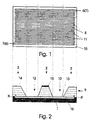
- FIG. 1 shows a sample chamber according to the invention, in which a channel or sample liquid path is formed by microstructured flow paths.
- Figure 2 shows this representation not to scale in the lateral section.
- trenches 8 which provide respective channel sections and are executed in parallel in the example, are introduced into an approximately 10 ⁇ 15 cm 2 and 500 ⁇ m thick plate 10, consisting of silicon or glass, by wet chemical etching.
- complete openings can also be provided instead of the aforementioned trenches 8, the remaining frame then being to be closed over the entire surface with a closed plate.
- the exposed trench areas are further closed by a cover 9, which comprises the assemblies above an axis XX, as shown in FIG. 4.
- the cover 9 is formed in the manner according to the invention from a silicon plate into which two thermally insulating grooves 12 are introduced in the example. At their base, these throats 12 form a membrane-like closure 13, which covers the trench regions which form the dwell zones of the sample liquid between the heating and cooling zones and is approximately 1 ⁇ m thick.
- the middle silicon web is provided with a thin-film heating element 15, by means of which the sample is heated on the opposite web base.
- a thermostated cooling not shown in more detail, is carried out via the two outer silicon webs remaining in the example.
- a continuous sample flow is ensured in the example by bridging channels 11 which are introduced into the cover 9 and which mutually connect individual trench starts to the respectively adjacent individual trench ends.
- required inlets and outlets can either be inserted in the plate 10 (as indicated in FIG. 1) or the cover 9.
- the overall device described is provided in the example with a carrier 16 which is made of a glass with low thermal conductivity.
- the individual trenches are given 8 trench widths of 500 ⁇ m and trench lengths of slightly less than 100 mm at trench depths of 400 ⁇ m, which, including the paths for the bridging channels, results in a total trench length of 0.4 m. It makes sense to add sample volumes of approx. 10 to 200 ⁇ l to the flow thermal cycler, which corresponds to the usual sample quantities.
- the heating zone can be designed within the scope of the invention in such a way that it is divided into two partial areas in such a way that a first heating zone of, for example, 4 mm width is formed in the flow direction, to which there is a thermal insulation zone (not shown) of 1 mm and thereon a second heating zone with a 2 mm expansion connects.
- said first heating zone can be acted upon by setting a corresponding heating output with a temperature of 72 ° C. and the second heating zone with a temperature of 92 ° C.
- a second thermal insulation zone of, for example, 1 mm extension could follow the second heating zone, followed by a cooling zone of, for example, 3 mm extension, which is kept at 55 ° C. by secondary cooling.
- a miniaturized thermal cycler designed in this way is particularly suitable for carrying out a polymerase chain reaction.
- a mixture of template, nucleoside triphosphates, primers and taq polymerase in buffer solution is applied to the feed, the respective composition of which is determined analogously to the known prior art.
- the flow rate is set to approximately 8 ⁇ l / min, so that the residence time per period is approximately 1 minute. Of these, 20 sec apply to the first heating zone, 10 sec to the second heating zone, 15 sec to the cooling zone and 5 sec each to the thermal insulation zones. It takes about 40 minutes to run through the entire miniaturized thermal cycler. During this time, forty amplification cycles take place in a volume element of 2 ⁇ l. When extended to 44 minutes (10% time extension), 34 ⁇ l are amplified.
- sample chamber according to the invention can be easily one Series production and is inexpensive, while large A variety of different sample chamber geometries can be produced, so that an adjustment for varying applications no further Brings difficulties.
Landscapes
- Chemical & Material Sciences (AREA)
- Health & Medical Sciences (AREA)
- Chemical Kinetics & Catalysis (AREA)
- General Health & Medical Sciences (AREA)
- Clinical Laboratory Science (AREA)
- Life Sciences & Earth Sciences (AREA)
- Biochemistry (AREA)
- Molecular Biology (AREA)
- Organic Chemistry (AREA)
- Dispersion Chemistry (AREA)
- Analytical Chemistry (AREA)
- Hematology (AREA)
- Apparatus Associated With Microorganisms And Enzymes (AREA)
- Measuring Or Testing Involving Enzymes Or Micro-Organisms (AREA)
Abstract
Description
Das Verfahren der Polymerase-Ketten-Reaktion ist in den letzten Jahren zur Vervielfachung bestimmter DNA-Sequenzen entwickelt worden und in seinen Grundsätzen von Darnell, J.; Lodish, H.; Baltimore, D. in "Molekulare Zellbiologie, Walter de Gruyter, Berlin-New York 1994, S. 256/257" ausgeführt. Unter anderem ist bei diesem Verfahren wesentlich, daß Gemische aus DNA-Sequenzen einer definierten Temperaturwechselbehandlung unterworfen werden. Dazu finden stationäre Probenbehandlungsapparaturen Verwendung, bei denen die entsprechenden Proben in Probenkammern eingegeben und periodisch einem Warm-Kalt-Temperaturzyklus unterworfen werden, wobei sich je nach definiert vorgegebenen Primern die jeweils gewünschten DNA-Sequenzen vervielfachen. Die Effektivität bislang bekannter Probenkammern wird dabei als nicht ausreichend angesehen. Aus diesem Grund ist in jüngster Zeit eine miniaturisierte Probenkammer vorgeschlagen worden (Northrup et al, DNA Amplification with Microfabricated reaction chamber, 7th International Conference on Solid State Sensors and Actuators, Proc. Transducers 1993, S. 924-26), die eine vierfach schnellere Vervielfachung gewünschter DNA-Sequenzen gegenüber bekannten Anordnungen ermöglicht. Diese bis zu 50 µl Probenflüssigkeit aufnehmende Probenkammer besteht aus einer strukturierten Siliziumzelle mit einer Längsausdehnung in der Größenordnung von 10 mm, welche in einer Probenangriffsrichtung von einer dünnen Membran abgeschlossen ist, über die die entsprechende Temperaturbeaufschlagung mittels miniaturisierter Heizelemente erfolgt. Auch bei dieser Vorrichtung wird die zu vervielfachende DNA-Sequenz über Mikrokanäle in die Kammer eingebracht, einer Polymerase-Ketten-Reaktion unterworfen und anschließend wieder abgezogen. Trotz der mit dieser Vorrichtung erzielten Vorteile haftet ihr im wesentlichen der Nachteil an, daß auch diese Probenkammer als Ganzes beheizt und gekühlt werden muß, womit sich nur begrenzte Temperaturwechselraten erreichen lassen. Insbesondere bei weiterer Reduzierung der Probengröße fällt dabei die parasitäre Wärmekapazität der Probenkammer und ggf. eines notwendigen Temperierblocks gegenüber der Probenflüssigkeit immer stärker ins Gewicht, so daß die prinzipiell bei kleinen Flüssigkeitsvolumina denkbaren hohen Temperaturwechselraten nicht erreicht werden können, wodurch die Effektivität des Verfahrens relativ gering bleibt. Darüber hinaus ist zwecks Erreichung jeweils konstanter Temperaturregimes für die Probenflüssigkeit ein relativ aufwendiger Steuer- und Regelaufwand erforderlich, wobei die erbrachte Heiz- bzw. Kühlleistung im wesentlichen nicht in der Probenfiüssigkeit, sondern in den sie umgebenden Baugruppen verbraucht wird.
Desweiteren ist aus US-PS 5,270,183 ein im Durchflußprinzip arbeitender Thermocycler bekannt geworden, bei dem die zu amplifizierende Probenflüssigkeit durch eine Rohrleitung geschickt wird, welche nacheinander um mehrere, auf unterschiedlichen Temperaturen gehaltene Zylinder ein oder mehrfach aufgewickelt ist. Grundsätzlich sind mit einer solchen Ausbildung auch relabiv kleine Probenmengen, bis herunter zu ca. 25 µl, amplifizierbar. Eine derartige Vorrichtung ist in ihrer Handhabung jedoch recht unpraktikabel und erfordert eine hohe Kunstfertigkeit vom Gerätehersteller, so daß sie für eine Serienfertigung gänzlich ungeeignet ist.
Durch die erfindungsgemäße Gestaltung des Probenaufnahmebereiches ist weiterhin gewährleistet, daß die in jeweils vorgesehenen Heiz- und kühlbereichen, im Folgenden genannt Heiz- und Kühlzonen, gerade einer Behandlung unterworfenen Probenteilvolumina einen homogenen Temperaturdurchsatz erfahren, was ebenfalls eine Ausbeuteerhöhung der zu amplifizierenden Substanz bewirkt. Weiterhin wird durch den anordnungsbedingten Wegfall von Heiz- und Kühlprozessen der Wandungsmaterialien und die drastische Minimierung parasitärer Wärmekapazitäten und Wärmeeinflüsse nicht nur ein erheblich geringerer Steuer- und Regelaufwand erforderlich, sondern der Gesamtprozeßdurchlauf erfährt auch eine wesentliche Zeitverkürzung. Dabei braucht jeweils nur soviel Heiz- und Kühlleistung eingespeist zu werden, wie im Probenflüssigkeitsstrom transportiert wird. Darüber hinaus ermöglicht die erfindungsgemäße Thermocyclerausbildung nicht nur eine kontinuierliche Prozeßführung, sondern auch einen seriellen Betrieb, indem unterschiedliche Substanzen nacheinander dem Thermocycler zuführbar sind, ohne daß es zu störenden Vermischungen mit der noch in der Anordnung befindlichen Probe kommen würde, was sich problemlos durch Einbringung eines kleinen Gaspuffervolumens bewerkstelligen läßt. Alle genannten Vorteile gewährleisten ebenso, daß das Verfahren der Polymerase-Ketten-Reaktion automatisiert durchgeführt werden kann. Weiterhin ergibt sich eine leichte Kombinierbarkeit mit anderen Verfahren, wie z.B. der Mikro-Gel-Elektrophorese, Mikro-Kapillar-Chromatografie und anderen Mikro-Trenn- und Charakterisierungsverfahren.
- Fig. 1
- eine Draufsicht auf eine erfindungsgemäße Probenkammer, bei der ein Probenflüssigkeitsweg durch mikrostrukturierte Flußwege gebildet ist und
- Fig. 2
- einen seitlichen Schnitt durch eine Probenkammer gemäß Fig. 1.
Mit dem zu Figur 1 und 2 gehörigen Ausführungsbeispiel sind bei möglichen Flußraten von ca. 0,1 µl/s, bei Probenverweilzeiten in den Heiz- zonenbereichen von ca. 20 sec, in den Kühlzonenbereichen von 30 sec und in den dazwischenliegenden Zonen von 10 sec, bei einer Einzelgrabenanzahl von 40, Gesamtdurchlaufzeiten zur Amplifizierung mit maximal möglicher Ausbeute von 40 min erreichbar, was eine deutliche Reduzierung unter die bisher bekannt gewordenen geringsten Zeiten bei gleichzeitig erhöhter Ausbeute bedeutet.
In diesem Beispiel kann die Heizzone im Rahmen der Erfindung so ausgebildet sein, daß sie in zwei Teilbereiche derart aufgeteilt ist, daß in Flußrichtung eine erste Heizzone von bspw. 4 mm Breite entsteht, an die sich eine nicht dargestellte thermische Isolationszone von 1 mm und daran eine zweite Heizzone mit 2 mm Ausdehnung anschließt. Auf diese Weise ist genannte erste Heizzone über Einstellung einer entsprechenden Heizleistung mit einer Temperatur von 72°C und die zweite Heizzone mit einer Temperatur von 92°C beaufschlagbar. An genannte zweite Heizzone könnte eine zweite thermische Isolationszone von bspw. 1 mm Ausdehnung folgen, an die sich eine Kühlzone von bspw. 3 mm Ausdehnung anschließt, die durch sekundäre Kühlung auf 55°C gehalten wird. Ein derart ausgebildeter miniaturisierter Thermocycler ist besonders zur Durchführung einer Polymerase-Kettenreaktion geeignet. Dabei wird am Zulauf ein Gemisch aus Template, Nukleosidtriphosphaten, Primern und taq-Polymerase in Pufferlösung appliziert, deren jeweilige Zusammensetzung analog zum bekannten Stand der Technik festgelegt wird. Die Flußrate wird auf ca. 8 µl/min eingestellt, so daß die Verweilzeit je Periode etwa 1 Minute beträgt. Davon entfallen auf genannte erste Heizzone 20 sec, 10 sec auf die zweite Heizzone, 15 sec auf die Kühlzone und jeweils 5 sec auf die thermischen Isolationszonen. Zum Durchlauf des gesamten miniaturisierten Thermocyclers werden damit ca. 40 Minuten benötigt. In dieser Zeit finden in einem Volumenelement von 2 µl vierzig Amplifikationszyklen statt. Bei einer Verlängerung auf 44 Minuten (10% Zeitverlängerung) werden 34 µl amplifiziert.
- 1 -
- Probenaufnahmebereich
- 2 -
- Heizzone
- 3 -
- Kühlzone
- 6 -
- Zulauf
- 7 -
- Ablauf
- 8 -
- Graben
- 9 -
- Abdeckung
- 10 -
- Silizium- oder Glasplättchen
- 11 -
- Überbrückungskanäle
- 12 -
- isolierende Kehlung
- 13 -
- membranartiger Abschluß
- 14 -
- Siliziumsteg
- 15 -
- Dünnschichtheizelement
- 16 -
- Träger
- X-X -
- Achse
Claims (8)
- Miniaturisierter Fluss-Thermocycler, umfassend einen zum Durchfluss flüssigen Mediums ausgebildeten Probenaufnahmebereich (1) mit einem Eintrittsbereich (6) und einem Austrittsbereich (7) für das flüssige Medium, wobei der Probenaufnahmebereich einen in einer Platte (10) gebildeten, durch eine Abdeckung (9) abgedeckten Kanal umfasst, welcher zwischen dem Eintrittsbereich (6) und dem Austrittsbereich (7) zum Bilden nebeneinander verlaufender Kanalabschnitte mehrfach mäanderartig gewunden ist, sowie eine Mehrzahl von Temperierbereichen, mit welchen das flüssige Medium in Wärmeübertragungs-Wechselwirkung tritt, umfassend an der Abdeckung (9) wenigstens einen Heizbereich und wenigstens einen von diesem durch eine in der Abdeckung (9) gebildete Kehlung (12) thermisch isolierten Kühlbereich, wobei vergleichbare Kanalabschnittsbereiche von dem wenigstens einen Heizbereich und dem wenigstens einen Kühlbereich derart erfasst sind, dass entlang des Kanals sich bewegendes flüssiges Medium alternierend von dem wenigstens einen Heizbereich und dem wenigstens einen Kühlbereich erfasste Kanalabschnittsbereiche durchströmt, und wobei in den Heiz- bzw. Kühlbereichen jeweilige Temperiereinrichtungen zur Erzeugung der erforderlichen Heiz- bzw. Kühltemperaturen vorgesehen sind.
- Miniaturisierter Fluss-Thermocycler nach Anspruch 1, dadurch gekennzeichnet, dass die Kanalabschnitte durch in eine Wandung eingebrachte Gräben gebildet sind, wobei die Wandung durch ein Silizium- bzw. Glasplättchen (10) gebildet ist, in welches die Gräben (8) parallel eingeätzt sind, dass die Gräben (8) an ihren Enden untereinander durch Überbrückungskanäle (11) in eine durchgehende Verbindung gebracht sind und dass der durch die Gräben und die Überbrückungskanäle gebildete Kanal von wenigstens je einem Heizbereich (2) und einem Kühlbereich (3) erfasst ist.
- Miniaturisierter Fluss-Thermocycler nach Anspruch 2, dadurch gekennzeichnet, dass die Überbrückungskanäle (11) in der Abdeckung (9) vorgesehen sind.
- Miniaturisierter Fluss-Thermocycler nach einem der Ansprüche 1 bis 3, dadurch gekennzeichnet, dass die zwischen dem wenigstens einen Heizbereich (2) und dem wenigstens einen Kühlbereich (3) vorgesehene Kehlung (12) an der von dem Kanal abgewandten Seite der Abdeckung (9) ausgebildet ist.
- Miniaturisierter Fluss-Thermocycler nach einem der Ansprüche 1 bis 4, dadurch gekennzeichnet, dass die Kehlung (12) einen membranartigen Abschluss (13) bildet.
- Miniaturisierter Fluss-Thermocycler nach einem der Ansprüche 1 bis 5, dadurch gekennzeichnet, dass die Abdeckung (12) aus einem Silizium-Plättchen gebildet ist.
- Miniaturisierter Fluss-Thermocycler nach einem der Ansprüche 1 bis 6, dadurch gekennzeichnet, dass der wenigstens eine Heizbereich (2) oder/und der wenigstens eine Kühlbereich (3) in Probendurchflussrichtung größenordnungsmäßig jeweils gleichlange Kanalabschnittsbereiche erfassen.
- Miniaturisierter Fluss-Thermocycler nach einem der Ansprüche 1 bis 7, dadurch gekennzeichnet, dass der wenigstens eine Heizbereich 2 oder/und der wenigstens eine Kühlbereich (3) in voneinander beabstandete Bereiche zur Bereitstellung unterschiedlicher Temperaturen aufteilbar ist.
Priority Applications (1)
| Application Number | Priority Date | Filing Date | Title |
|---|---|---|---|
| EP00108592A EP1022059B1 (de) | 1994-09-30 | 1995-09-12 | Miniaturisierter Fluss-Thermocycler |
Applications Claiming Priority (3)
| Application Number | Priority Date | Filing Date | Title |
|---|---|---|---|
| DE4435107 | 1994-09-30 | ||
| DE4435107A DE4435107C1 (de) | 1994-09-30 | 1994-09-30 | Miniaturisierter Fluß-Thermocycler |
| PCT/EP1995/003580 WO1996010456A1 (de) | 1994-09-30 | 1995-09-12 | Miniaturisierter fluss-thermocycler |
Related Child Applications (1)
| Application Number | Title | Priority Date | Filing Date |
|---|---|---|---|
| EP00108592A Division EP1022059B1 (de) | 1994-09-30 | 1995-09-12 | Miniaturisierter Fluss-Thermocycler |
Publications (2)
| Publication Number | Publication Date |
|---|---|
| EP0731732A1 EP0731732A1 (de) | 1996-09-18 |
| EP0731732B1 true EP0731732B1 (de) | 2001-12-05 |
Family
ID=6529703
Family Applications (2)
| Application Number | Title | Priority Date | Filing Date |
|---|---|---|---|
| EP00108592A Expired - Lifetime EP1022059B1 (de) | 1994-09-30 | 1995-09-12 | Miniaturisierter Fluss-Thermocycler |
| EP95932718A Expired - Lifetime EP0731732B1 (de) | 1994-09-30 | 1995-09-12 | Miniaturisierter fluss-thermocycler |
Family Applications Before (1)
| Application Number | Title | Priority Date | Filing Date |
|---|---|---|---|
| EP00108592A Expired - Lifetime EP1022059B1 (de) | 1994-09-30 | 1995-09-12 | Miniaturisierter Fluss-Thermocycler |
Country Status (4)
| Country | Link |
|---|---|
| US (1) | US5716842A (de) |
| EP (2) | EP1022059B1 (de) |
| DE (1) | DE4435107C1 (de) |
| WO (1) | WO1996010456A1 (de) |
Families Citing this family (85)
| Publication number | Priority date | Publication date | Assignee | Title |
|---|---|---|---|---|
| DE19519015C1 (de) * | 1995-05-24 | 1996-09-05 | Inst Physikalische Hochtech Ev | Miniaturisierter Mehrkammer-Thermocycler |
| DE19646116A1 (de) * | 1996-11-08 | 1998-05-14 | Eppendorf Geraetebau Netheler | Temperierblock mit Aufnahmen |
| DE19655282B4 (de) * | 1996-11-08 | 2005-04-07 | Eppendorf Ag | Temperierblock mit Temperiereinrichtungen |
| DE29623597U1 (de) | 1996-11-08 | 1999-01-07 | Eppendorf - Netheler - Hinz Gmbh, 22339 Hamburg | Temperierblock mit Temperiereinrichtungen |
| DE19646115C2 (de) * | 1996-11-08 | 2000-05-25 | Eppendorf Geraetebau Netheler | Verwendung von Temperiereinrichtungen zur Temperierung eines Temperierblockes |
| DE19655141C5 (de) * | 1996-11-08 | 2013-12-05 | Eppendorf Ag | Gradienten-Temperierblock für Laborthermostaten |
| DE19646114B4 (de) * | 1996-11-08 | 2004-09-16 | Eppendorf Ag | Laborthermostat mit Temperierblöcken |
| US6143496A (en) | 1997-04-17 | 2000-11-07 | Cytonix Corporation | Method of sampling, amplifying and quantifying segment of nucleic acid, polymerase chain reaction assembly having nanoliter-sized sample chambers, and method of filling assembly |
| US6896855B1 (en) | 1998-02-11 | 2005-05-24 | Institut Fuer Physikalische Hochtechnologie E.V. | Miniaturized temperature-zone flow reactor |
| US6200531B1 (en) * | 1998-05-11 | 2001-03-13 | Igen International, Inc. | Apparatus for carrying out electrochemiluminescence test measurements |
| GB9826237D0 (en) | 1998-11-30 | 1999-01-20 | Hybaid Ltd | Thermal cycler |
| EP1045038A1 (de) | 1999-04-08 | 2000-10-18 | Hans-Knöll-Institut Für Naturstoff-Forschung E.V. | Thermisches Kreisprozessgerät mit Wärmeblock |
| AU782726B2 (en) * | 1999-07-28 | 2005-08-25 | Commissariat A L'energie Atomique | Integration of biochemical protocols in a continuous flow microfluidic device |
| FR2796863B1 (fr) * | 1999-07-28 | 2001-09-07 | Commissariat Energie Atomique | Procede et dispositif permettant de realiser en flux continu un protocole de traitement thermique sur une substance |
| DE19943187B4 (de) * | 1999-09-09 | 2006-05-04 | Kendro Laboratory Products Gmbh | Verfahren zur Behandlung von Probenmaterial in einem Probengefäß sowie Vorrichtung |
| DE29917313U1 (de) * | 1999-10-01 | 2001-02-15 | MWG-BIOTECH AG, 85560 Ebersberg | Vorrichtung zur Durchführung chemischer oder biologischer Reaktionen |
| DE60032113T2 (de) * | 2000-02-11 | 2007-06-28 | Stmicroelectronics S.R.L., Agrate Brianza | Integrierte Vorrichtung zur mikrofluidischen Temperaturregelung und dessen Herstellungsverfahren |
| EP1269171B1 (de) * | 2000-03-07 | 2006-05-31 | Northeastern University | Paralleles array unabhängiger thermostaten für säulentrennungen |
| US20010048900A1 (en) * | 2000-05-24 | 2001-12-06 | Bardell Ronald L. | Jet vortex mixer |
| US7025120B2 (en) * | 2000-09-05 | 2006-04-11 | Oldenburg Kevin R | Rapid thermal cycling device |
| US6640891B1 (en) | 2000-09-05 | 2003-11-04 | Kevin R. Oldenburg | Rapid thermal cycling device |
| DE60032772T2 (de) | 2000-09-27 | 2007-11-08 | Stmicroelectronics S.R.L., Agrate Brianza | Integrierter chemischer Mikroreaktor mit thermisch isolierten Messelektroden und Verfahren zu dessen Herstellung |
| US7727479B2 (en) * | 2000-09-29 | 2010-06-01 | Applied Biosystems, Llc | Device for the carrying out of chemical or biological reactions |
| US6509186B1 (en) | 2001-02-16 | 2003-01-21 | Institute Of Microelectronics | Miniaturized thermal cycler |
| US6432695B1 (en) | 2001-02-16 | 2002-08-13 | Institute Of Microelectronics | Miniaturized thermal cycler |
| US6586233B2 (en) * | 2001-03-09 | 2003-07-01 | The Regents Of The University Of California | Convectively driven PCR thermal-cycling |
| US20030032172A1 (en) * | 2001-07-06 | 2003-02-13 | The Regents Of The University Of California | Automated nucleic acid assay system |
| DE10149684B4 (de) * | 2001-10-09 | 2005-02-17 | Clondiag Chip Technologies Gmbh | Vorrichtung zur Halterung eines Substanzbibliothekenträgers |
| US20030116552A1 (en) * | 2001-12-20 | 2003-06-26 | Stmicroelectronics Inc. | Heating element for microfluidic and micromechanical applications |
| US7614444B2 (en) | 2002-01-08 | 2009-11-10 | Oldenburg Kevin R | Rapid thermal cycling device |
| US7373968B2 (en) * | 2002-01-08 | 2008-05-20 | Kevin R. Oldenburg | Method and apparatus for manipulating an organic liquid sample |
| US7179639B2 (en) * | 2002-03-05 | 2007-02-20 | Raveendran Pottathil | Thermal strip thermocycler |
| JP3891131B2 (ja) * | 2002-03-29 | 2007-03-14 | カシオ計算機株式会社 | 化学反応装置及び電源システム |
| TW592830B (en) * | 2002-03-29 | 2004-06-21 | Casio Computer Co Ltd | Chemical reaction apparatus and power supply system |
| AU2003249350A1 (en) * | 2002-06-20 | 2004-01-06 | Igen International, Inc | Electrochemiluminescence flow cell and flow cell components |
| JP4048864B2 (ja) * | 2002-07-29 | 2008-02-20 | カシオ計算機株式会社 | 小型化学反応装置およびその製造方法 |
| JP3979219B2 (ja) | 2002-08-07 | 2007-09-19 | カシオ計算機株式会社 | 小型化学反応装置 |
| US20040038385A1 (en) * | 2002-08-26 | 2004-02-26 | Langlois Richard G. | System for autonomous monitoring of bioagents |
| KR100452946B1 (ko) * | 2002-11-26 | 2004-10-14 | 한국전자통신연구원 | 저전력형 미세 열순환 소자 및 그 제조 방법 |
| DE10258398A1 (de) * | 2002-12-11 | 2004-08-12 | Hans-Knöll-Institut für Naturstoff-Forschung e.V. | Verfahren zur Amplifikation von DNA |
| EP1579203A1 (de) * | 2002-12-20 | 2005-09-28 | Northeastern University | Präzisionsgesteuerter thermostat |
| US8676383B2 (en) * | 2002-12-23 | 2014-03-18 | Applied Biosystems, Llc | Device for carrying out chemical or biological reactions |
| US20070184548A1 (en) * | 2002-12-23 | 2007-08-09 | Lim Hi Tan | Device for carrying out chemical or biological reactions |
| US8043849B2 (en) * | 2004-02-24 | 2011-10-25 | Thermal Gradient | Thermal cycling device |
| EP2354256B1 (de) * | 2004-02-24 | 2019-04-10 | Thermal Gradient | Vorrichtung für thermisches cycling |
| US20080118955A1 (en) * | 2004-04-28 | 2008-05-22 | International Business Machines Corporation | Method for precise temperature cycling in chemical / biochemical processes |
| US20050244933A1 (en) * | 2004-04-28 | 2005-11-03 | International Business Machines Corporation | Method and apparatus for precise temperature cycling in chemical/biochemical processes |
| US7622296B2 (en) * | 2004-05-28 | 2009-11-24 | Wafergen, Inc. | Apparatus and method for multiplex analysis |
| US20060024204A1 (en) * | 2004-08-02 | 2006-02-02 | Oldenburg Kevin R | Well plate sealing apparatus and method |
| US20060246493A1 (en) | 2005-04-04 | 2006-11-02 | Caliper Life Sciences, Inc. | Method and apparatus for use in temperature controlled processing of microfluidic samples |
| JP5590796B2 (ja) | 2005-06-03 | 2014-09-17 | ボード・オブ・リージェンツ・オブ・ザ・ユニバーシティ・オブ・テキサス・システム | 電気化学および単一ファラデー電極による電気化学発光 |
| US8721161B2 (en) * | 2005-09-15 | 2014-05-13 | Alcatel Lucent | Fluid oscillations on structured surfaces |
| US8734003B2 (en) | 2005-09-15 | 2014-05-27 | Alcatel Lucent | Micro-chemical mixing |
| US20070059213A1 (en) * | 2005-09-15 | 2007-03-15 | Lucent Technologies Inc. | Heat-induced transitions on a structured surface |
| KR100768089B1 (ko) * | 2005-11-30 | 2007-10-18 | 한국전자통신연구원 | 친화 크로마토그래피 미세장치, 이의 제조방법. |
| JP5254949B2 (ja) | 2006-03-15 | 2013-08-07 | マイクロニクス, インコーポレイテッド | 一体型の核酸アッセイ |
| TWI296608B (en) * | 2006-04-14 | 2008-05-11 | Ind Tech Res Inst | Microscale heating module |
| WO2008147382A1 (en) * | 2006-09-27 | 2008-12-04 | Micronics, Inc. | Integrated microfluidic assay devices and methods |
| EP2548647B1 (de) | 2006-10-20 | 2018-08-15 | CLONDIAG GmbH | Testvorrichtungen und-Verfahren zum Nachweis von Analyten |
| DE102006053451B4 (de) * | 2006-11-11 | 2008-11-27 | Microfluidic Chipshop Gmbh | Mikrofluidische Plattform zur Temperierung von Substanzen und/oder zur Durchführung von zu temperierenden Reaktionen |
| DE102006053452A1 (de) * | 2006-11-11 | 2008-05-15 | Microfluidic Chipshop Gmbh | Geräte zur Temperierung und Steuerung von fluidischen Plattformen |
| EP2109627A4 (de) | 2007-01-22 | 2014-07-23 | Wafergen Inc | Vorrichtung für chemische reaktionen mit hohem durchsatz |
| JP5282088B2 (ja) | 2007-06-21 | 2013-09-04 | ジェン−プロウブ インコーポレイテッド | 処理実行に使用する機器および容器 |
| WO2009049268A1 (en) | 2007-10-12 | 2009-04-16 | Rheonix, Inc. | Integrated microfluidic device and methods |
| JP5514807B2 (ja) * | 2009-04-24 | 2014-06-04 | 株式会社 メドレックス | 薬液担持用治具とそれを用いたマイクロニードルへの薬剤塗布方法 |
| US9599407B2 (en) * | 2009-07-29 | 2017-03-21 | Tokitae Llc | System and structure for heating or sterilizing a liquid stream |
| US9132423B2 (en) | 2010-01-29 | 2015-09-15 | Micronics, Inc. | Sample-to-answer microfluidic cartridge |
| JP6117694B2 (ja) | 2010-04-09 | 2017-04-19 | ライフ テクノロジーズ コーポレーション | 動的制御を用いた熱サイクラ器具に対する熱均一性改良 |
| JP5644187B2 (ja) * | 2010-05-31 | 2014-12-24 | 株式会社島津製作所 | カラムオーブン |
| JP5892709B2 (ja) * | 2010-11-08 | 2016-03-23 | ビージー リサーチ エルティーディーBg Research Ltd | 低容量生物学的反応容器の加熱及び冷却 |
| US9057687B2 (en) | 2012-04-20 | 2015-06-16 | Mocon, Inc. | Calibration vial and technique for calibrating a fiber optic oxygen sensing needle |
| EP2935908B1 (de) | 2012-12-21 | 2019-08-14 | PerkinElmer Health Sciences, Inc. | Fluidkreisläufe und zugehörige herstellungsverfahren |
| WO2014100743A2 (en) | 2012-12-21 | 2014-06-26 | Micronics, Inc. | Low elasticity films for microfluidic use |
| EP2935559B1 (de) | 2012-12-21 | 2020-09-16 | PerkinElmer Health Sciences, Inc. | Fluoreszenznachweissystem |
| EP2994543B1 (de) | 2013-05-07 | 2018-08-15 | Micronics, Inc. | Vorrichtung zur herstellung und analyse von nukleinsäuren |
| US10386377B2 (en) | 2013-05-07 | 2019-08-20 | Micronics, Inc. | Microfluidic devices and methods for performing serum separation and blood cross-matching |
| EP2994532B1 (de) | 2013-05-07 | 2017-11-15 | Micronics, Inc. | Verfahren zur herstellung von nukleinsäurehaltigen proben mittels tonmineralien und alkalischen lösungen |
| SG11201601275UA (en) | 2013-09-16 | 2016-04-28 | Life Technologies Corp | Apparatuses, systems and methods for providing thermocycler thermal uniformity |
| WO2015126621A1 (en) | 2014-02-18 | 2015-08-27 | Life Technologies Corporation | Apparatuses, systems and methods for providing scalable thermal cyclers and isolating thermoelectric devices |
| WO2016134342A1 (en) | 2015-02-20 | 2016-08-25 | Wafergen, Inc. | Method for rapid accurate dispensing, visualization and analysis of single cells |
| CA3162752A1 (en) * | 2015-04-09 | 2016-10-13 | Angle Europe Limited | Method for performing a biological assay |
| KR102415232B1 (ko) | 2015-04-20 | 2022-07-04 | 한국전자통신연구원 | 마이크로 가열 장치 |
| US11460405B2 (en) | 2016-07-21 | 2022-10-04 | Takara Bio Usa, Inc. | Multi-Z imaging and dispensing with multi-well devices |
| CN113771333A (zh) * | 2021-09-03 | 2021-12-10 | 深圳市安和达塑胶制品有限公司 | 一种具有隔离槽结构且便于成型的双层出料模具 |
| EP4630582A1 (de) | 2022-12-08 | 2025-10-15 | Becton, Dickinson and Company | Vollautomatische dpcr-systeme und verfahren zur verwendung davon |
Family Cites Families (7)
| Publication number | Priority date | Publication date | Assignee | Title |
|---|---|---|---|---|
| GB8917963D0 (en) * | 1989-08-05 | 1989-09-20 | Scras | Apparatus for repeated automatic execution of a thermal cycle for treatment of biological samples |
| SE470347B (sv) * | 1990-05-10 | 1994-01-31 | Pharmacia Lkb Biotech | Mikrostruktur för vätskeflödessystem och förfarande för tillverkning av ett sådant system |
| US5270183A (en) * | 1991-02-08 | 1993-12-14 | Beckman Research Institute Of The City Of Hope | Device and method for the automated cycling of solutions between two or more temperatures |
| US5498392A (en) * | 1992-05-01 | 1996-03-12 | Trustees Of The University Of Pennsylvania | Mesoscale polynucleotide amplification device and method |
| DE69319427T2 (de) * | 1992-05-01 | 1998-12-10 | Univ Pennsylvania | Analyse bei messung des durchflusswiderstandes |
| US5587128A (en) * | 1992-05-01 | 1996-12-24 | The Trustees Of The University Of Pennsylvania | Mesoscale polynucleotide amplification devices |
| US5639423A (en) * | 1992-08-31 | 1997-06-17 | The Regents Of The University Of Calfornia | Microfabricated reactor |
-
1994
- 1994-09-30 DE DE4435107A patent/DE4435107C1/de not_active Expired - Fee Related
-
1995
- 1995-09-12 WO PCT/EP1995/003580 patent/WO1996010456A1/de not_active Ceased
- 1995-09-12 EP EP00108592A patent/EP1022059B1/de not_active Expired - Lifetime
- 1995-09-12 US US08/649,632 patent/US5716842A/en not_active Expired - Lifetime
- 1995-09-12 EP EP95932718A patent/EP0731732B1/de not_active Expired - Lifetime
Also Published As
| Publication number | Publication date |
|---|---|
| DE4435107C1 (de) | 1996-04-04 |
| EP1022059A2 (de) | 2000-07-26 |
| EP0731732A1 (de) | 1996-09-18 |
| US5716842A (en) | 1998-02-10 |
| WO1996010456A1 (de) | 1996-04-11 |
| EP1022059B1 (de) | 2002-08-28 |
| EP1022059A3 (de) | 2000-12-27 |
Similar Documents
| Publication | Publication Date | Title |
|---|---|---|
| EP1022059B1 (de) | Miniaturisierter Fluss-Thermocycler | |
| EP1054735B1 (de) | Miniaturisierter temperaturzonen flussreaktor | |
| DE19519015C1 (de) | Miniaturisierter Mehrkammer-Thermocycler | |
| DE69322774T2 (de) | Polynukleotide amplifikationsanalyse mit einer mikrofabrizierten vorrichtung | |
| EP1216098B1 (de) | Vorrichtung zur durchführung chemischer oder biologischer reaktionen | |
| DE69219566T2 (de) | Verfahren und Gerät zur Temperaturregelung von Vielfachproben | |
| DE10227593B4 (de) | Strömungsschaltungs-Mikrobauelemente | |
| DE69525036T2 (de) | Gerät zur amplifikation von polynukleotiden im mesomassstab | |
| DE60018733T2 (de) | Vorrichtung und verfahren zur probenanalyse | |
| DE60021077T2 (de) | Vorrichtung und verfahren zur probenabgabe | |
| DE60217375T2 (de) | Verfahren und vorrichtung zur amplifikation von nukleinsäuresequenzen mittels thermischer konvektion | |
| DE10106008A1 (de) | PCR-Mikroreaktor zum Vermehren von DNA unter Verwendung von Mikromengen eines Probenfluids | |
| DE19717085C2 (de) | Verfahren und Geräte für extrem schnelle DNA-Vervielfachung durch Polymerase-Kettenreaktionen (PCR) | |
| US20010046701A1 (en) | Nucleic acid amplification and detection using microfluidic diffusion based structures | |
| DE102009035270A1 (de) | Ein Einweg-Multiplex-Polymerase-Kettenreaktions(PCR)-Chip und Gerät | |
| DE10309583A1 (de) | Mikroplatte mit einem integrierten mikrofluidischen System zum parallelen Verarbeiten winziger Fluidvolumen | |
| DE19534632A1 (de) | System zur Temperaturwechselbehandlung von Probenflüssigkeiten | |
| DE102010041579A1 (de) | Mikrofluideinheit mit Trennsäulen | |
| WO1995025592A1 (de) | Verfahren zur bearbeitung von nukleinsaüren | |
| EP2331260B1 (de) | Vorrichtung zum temperieren eines rotationssymmetrischen behältnisses | |
| WO2010040758A1 (de) | Vorrichtung und verfahren zur ausführung mehrerer paralleler pcr-reaktionen im durchflussverfahren | |
| DE19943187B4 (de) | Verfahren zur Behandlung von Probenmaterial in einem Probengefäß sowie Vorrichtung | |
| DE3927467C2 (de) | Vorrichtung und Verwendung einer Vorrichtung zur Trennung und und Detektion von Komponenten eines Stoffgemisches durch Temperaturgradienten-Gelelektrophorese | |
| WO2004103564A1 (de) | Vorrichtung und verfahren zum positionieren und ausschleusen von in separationsmedium eingebetteten fluidkompartimenten | |
| DE102017011226B3 (de) | Automatisiertes, integriertes mikrofluidisches System für die Hochdurchsatz-Klonierung |
Legal Events
| Date | Code | Title | Description |
|---|---|---|---|
| PUAI | Public reference made under article 153(3) epc to a published international application that has entered the european phase |
Free format text: ORIGINAL CODE: 0009012 |
|
| 17P | Request for examination filed |
Effective date: 19960607 |
|
| AK | Designated contracting states |
Kind code of ref document: A1 Designated state(s): FR GB IT |
|
| 17Q | First examination report despatched |
Effective date: 19990616 |
|
| GRAG | Despatch of communication of intention to grant |
Free format text: ORIGINAL CODE: EPIDOS AGRA |
|
| GRAG | Despatch of communication of intention to grant |
Free format text: ORIGINAL CODE: EPIDOS AGRA |
|
| GRAG | Despatch of communication of intention to grant |
Free format text: ORIGINAL CODE: EPIDOS AGRA |
|
| GRAH | Despatch of communication of intention to grant a patent |
Free format text: ORIGINAL CODE: EPIDOS IGRA |
|
| GRAH | Despatch of communication of intention to grant a patent |
Free format text: ORIGINAL CODE: EPIDOS IGRA |
|
| GRAA | (expected) grant |
Free format text: ORIGINAL CODE: 0009210 |
|
| AK | Designated contracting states |
Kind code of ref document: B1 Designated state(s): FR GB IT |
|
| REG | Reference to a national code |
Ref country code: GB Ref legal event code: IF02 |
|
| GBT | Gb: translation of ep patent filed (gb section 77(6)(a)/1977) |
Effective date: 20011206 |
|
| ET | Fr: translation filed | ||
| PLBE | No opposition filed within time limit |
Free format text: ORIGINAL CODE: 0009261 |
|
| STAA | Information on the status of an ep patent application or granted ep patent |
Free format text: STATUS: NO OPPOSITION FILED WITHIN TIME LIMIT |
|
| 26N | No opposition filed | ||
| PGFP | Annual fee paid to national office [announced via postgrant information from national office to epo] |
Ref country code: IT Payment date: 20100922 Year of fee payment: 16 |
|
| PGFP | Annual fee paid to national office [announced via postgrant information from national office to epo] |
Ref country code: GB Payment date: 20110929 Year of fee payment: 17 |
|
| PGFP | Annual fee paid to national office [announced via postgrant information from national office to epo] |
Ref country code: FR Payment date: 20111018 Year of fee payment: 17 |
|
| GBPC | Gb: european patent ceased through non-payment of renewal fee |
Effective date: 20120912 |
|
| REG | Reference to a national code |
Ref country code: FR Ref legal event code: ST Effective date: 20130531 |
|
| PG25 | Lapsed in a contracting state [announced via postgrant information from national office to epo] |
Ref country code: GB Free format text: LAPSE BECAUSE OF NON-PAYMENT OF DUE FEES Effective date: 20120912 |
|
| PG25 | Lapsed in a contracting state [announced via postgrant information from national office to epo] |
Ref country code: IT Free format text: LAPSE BECAUSE OF NON-PAYMENT OF DUE FEES Effective date: 20120912 Ref country code: FR Free format text: LAPSE BECAUSE OF NON-PAYMENT OF DUE FEES Effective date: 20121001 |